The initial phases of electromagnetic sinusoidal oscillations of the primary and secondary voltage, with a frequency of the same value, can differ significantly by a certain phase shift angle (angle φ). Variable quantities can change repeatedly over a certain period of time with a certain frequency. If electrical processes are unchanged and the phase shift is zero, this indicates synchronism of sources of alternating voltage values, for example, transformers. Phase shift is a determining factor of power factor in AC electrical networks.
The phase shift angle is found if necessary, then if one of the signals is a reference signal, and the second signal with a phase at the very beginning coincides with the phase shift angle.
The phase shift angle is measured using a device that has a normalized error.
The phase meter can measure the shift angle within the range from 0° to 360°, in some cases from -180°C to +180°C, and the range of measured signal frequencies can range from 20Hz to 20 GHz. The measurement is guaranteed if the input signal voltage is between 1 mV and 100 V, but if the input signal voltage exceeds these limits, the measurement accuracy is not guaranteed.
How does a capacitor shift phase?
The capacitor shifts the sine wave by plus 90 degrees and the inductance by minus 90 degrees. Thanks to this shift, the engine starts, and if there is a powerful load on the shaft, then a starting capacitor is briefly connected in parallel with the working capacitor.
Interesting materials:
How to write an advertising slogan correctly? How to cut meat correctly? How to properly tension a chain on a speed bike? How to wear a watch and bracelet correctly for men? How to wear a headscarf correctly? How to wear medals on a jacket? How to wear women's stockings correctly? How to properly treat a child’s ears after a piercing? How to address the captain correctly? How to properly set up a parrot's cage?
AC current and voltage phase shift
DC power, as we already know, is equal to the product of voltage and current. But with constant current, the directions of current and voltage always coincide. With alternating current, the coincidence of the directions of current and voltage occurs only in the absence of capacitors and inductors in the current circuit.
For this case, the power formula
remains fair.
Figure 1 shows the curve of changes in instantaneous power values for this case (the direction of the current and voltage are the same). Let us pay attention to the fact that the directions of the voltage and current vectors in this case coincide, that is, the phases of the current and voltage are always the same .
Figure 1. Phase shift of current and voltage. There is no phase shift, the power is always positive.
If there is a capacitor or inductor in the AC circuit, the phases of the current and voltage will not coincide.
Read about the reasons for this discrepancy in my textbooks for a capacitive circuit and for an inductive circuit, but now let’s establish how it will affect the amount of alternating current power.
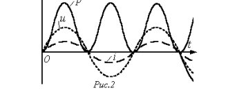
Let's imagine that at the beginning of rotation, the radius vectors of current and voltage have different directions. Since both vectors rotate at the same speed, the angle between them will remain constant throughout their rotation. Figure 2 shows the case when the current vector Im behind the voltage vector Um by an angle of 45°.
Figure 2. Phase shift of current and voltage. The phases of current and voltage are shifted by 45, the power becomes negative at some periods of time.
Let's consider how the current and voltage will change. From the constructed sinusoids of current and voltage, it can be seen that when the voltage passes through zero, the current has a negative value.
Then the voltage reaches its maximum value and begins to decrease, and the current, although it becomes positive, has not yet reached its maximum value and continues to increase. The voltage has changed its direction, but the current still flows in the same direction, etc. The current phase always lags behind the voltage phase. shift between the voltage and current phases , called phase shift.
Indeed, if we look at Figure 2, we will notice that the current sinusoid is shifted to the right relative to the voltage sinusoid. Since we plot the degrees of rotation along the horizontal axis, the phase shift can also be measured in degrees. It is easy to see that the phase shift is exactly equal to the angle between the radius vectors of current and voltage.
Due to the current phase lagging behind the voltage phase, its direction at some moments will not coincide with the direction of the voltage. At these moments, the current power will be negative, since the product of a positive value and a negative value will always be negative. This means that the external electrical circuit at these moments becomes not a consumer of electrical energy, but a source of it. Some of the energy supplied to the circuit during the portion of the period when the power was positive is returned to the energy source during the portion of the period when the power is negative.
The greater the phase shift, the longer the parts of the period during which the power becomes negative become, and, consequently, the less will be the average current power.
With a phase shift of 90°, the power will be positive for one quarter of the period and negative for the other quarter of the period. Consequently, the average power of the current will be zero , and the current will not produce any work (Figure 3).
Figure 3. Phase shift of current and voltage. The phases of current and voltage are shifted by 90, the power is positive during one quarter of the period, and negative during the other. On average, the power is zero.
It is now clear that the alternating current power in the presence of a phase shift will be less than the product of the effective values of current and voltage, i.e. the formula
in this case will be incorrect
DID YOU LIKE THE ARTICLE? SHARE WITH YOUR FRIENDS ON SOCIAL NETWORKS!
Related materials:
- The concept of alternating current
- Receiving alternating current
- Period, frequency, amplitude and phase of alternating current
- RMS value of current and voltage
- AC power
Comments
#14 rrr 03.12.2018 14:20 Please tell me how to draw microprocessor circuits in this application. There are no necessary circuits in this library, and drawing with rectangles is very time consuming and not practical
Quote
#13 Almira 06/10/2018 06:52 Question: does the phase shift depend on the value of active resistance? If no/yes, why?
Quote
#12 Alexander 40 07/11/2017 19:15 why does a 220 volt transformer connected in series with the primary winding get very hot? Probably 220 is added to a charged capacitor of 1 microforad due to the phase shift and it turns out about 440 volts on the primary winding.
Quote
#11 Vitaly 12/15/2016 21:03 I quote the Master:
I quote Stas: What nonsense. When the phases are shifted by 90*, the current does not do any work. We take an electric hotplate, connect a capacitor in series and plug it into the socket, everything works, the hotplate heats up, the current does work.
Nobody said that it wouldn't warm up!
Read carefully! Tile - This is active power Even with a network shift of 90 degrees, the tile will not affect the angle and vice versa) if I’m wrong, correct me, just guesses) Quote #10 Rostik 06/07/2016 02:28 But the question is, is it possible to do this by taking one phase from the 220 network and throw one phase wire straight to the stove and the second wire from the same phase through the condenser and then to the electric stove, that is, make a phase circuit; will the stove work more powerfully or nothing will happen?
Quote
Sed 01/20/2016 17:57 topic not solved
Quote
Vladimir 24 12/03/2015 08:50 Thank you. The ongoing processes are described very intelligibly, clearly, and clearly. Nice article and useful.
Quote
zed 05/26/2015 08:25 Stas, if you connect a capacitor to a tile with active resistance, then there will be a phase shift, but not 90. Therefore, the tile will heat, but not as efficiently as without a capacitor... This is mathematics...
Quote
Andrey 12/28/2014 00:44 More articles like this, you’re a great author, I tried to understand a three-phase circuit many times and all the formula triangles were useless and it all ended there. Until I figured out to replace each winding with just a battery with a different voltage and direction as per the sine wave graph, and lo and behold, I began to combine and everything worked. Then I finally understood what zero is. For more people like you, these academics and so on are of no use. so they will write that life is not enough to figure it out. It feels like they are purposefully confusing so that only the smartest of the people can guess.
Quote
Master 10.22.2014 18:33 I quote Stas:
What nonsense. When the phases are shifted by 90*, the current does not do any work. We take an electric hotplate, connect a capacitor in series and plug it into the socket, everything works, the hotplate heats up, the current does work.
Nobody said that it wouldn't warm up!
Read carefully! Quote everything is absolutely correct 12/13/2013 14:18
Quote
Administrator 12/12/2013 07:42 Do not substitute concepts! The tile is a resistive load, in this case the phase difference between current and voltage is zero. And on the capacitor that you connected to the circuit, the voltage lags behind the current by 90 degrees (do not forget that the current when connected in series is common through all elements). Therefore, the power on the capacitor will change during one quarter of the period will be positive, and during the other quarter of the period it will be negative. Total for the period P=0. Therefore, the work will be zero. But in tiles it’s different, there is no shift P=I*U. For clarification, look at the pictures:
That’s why capacitors are used as “watt-free resistors”
Quote
Stas 12/11/2013 10:59 What nonsense. When the phases are shifted by 90*, the current does not do any work. We take an electric hotplate, connect a capacitor in series and plug it into the socket, everything works, the hotplate heats up, the current does work.
Quote
tmp 22.11.2013 18:05 Simple and accessible
Quote
Update list of comments
Add a comment
Phase (Phase Voltage) Misalignment in a Three-Phase Electrical Network
• Essence of the phenomenon • Causes of occurrence • Consequences • Methods for eliminating phase imbalance • Alternative technology. • Range of changes in phase voltages.
• Practical use.
The essence of the phenomenon
Phase imbalance manifests itself in three-phase four- (five-) wire networks with a solidly grounded neutral with voltages up to 1000 V.
As a rule, a low-voltage three-phase electrical network with a voltage of 400 V (0.4 kV) contains sources of electricity, the windings of which are connected in a “star” with a zero output.
If a three-phase network is four-wire, then the neutral conductor performs two functions. First function: the neutral working conductor is used to connect single-phase electrical receivers. Second function: the neutral working conductor is used to operate the protection. In a five-wire network, each of the two listed functions has its own wire.
In low-voltage networks, primary and secondary sources of electricity (power supplies) are distinguished, regardless of the method of obtaining electrical energy.
Primary sources include those that directly generate electricity, for example, electric generators (hydraulic units, steam turbines, diesel engines, and gas engines can be used as drives).
Secondary sources include those that convert electrical energy from primary sources, as a rule, these are transformers installed in transformer substations (TS).
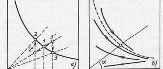
An ideal model that displays the relationship and relative position of phase and line voltages can be depicted in the form of an equilateral triangle with vertices “A”, “B”, “C” and .Vectors AB, BC and CA (lying on the sides of the triangle) are line voltages (380V ).The vectors drawn from the center of the triangle to its vertices - 0A, 0B and 0C - are phase voltages. Ideally, they are equal to each other 0A=0B=0C and shifted relative to each other by an angle of 120°, that is└A0B=└B0C =└C0A=120°.
This model is ideal and there is no phase voltage imbalance.
Since many consumers, including single-phase ones, are connected to TP transformers, at every random moment in time one can expect that the loads in different phases will be different. Moreover, even if single-phase loads are the same in size, then their switching on or off under load cannot occur synchronously. The situation arises RA > RB > RC ≠ 0, where “R” is the load resistance, and, accordingly, “RA” is the load resistance on phase A, “RB” is the load resistance on phase B, “RC” is load resistance on phase C.
The difference in phase loads in magnitude and nature creates conditions for the occurrence of phase voltage imbalance.
If we look at the equilateral triangle described above, then graphically it will look like this: point 0 in the center of the triangle, from which the vectors of ideal phase voltages of 220V 0A, 0B and 0C emanate, is shifted relative to the center of the triangle. Let's call it 0′.
The phase voltage vectors themselves are shifted at an arbitrary angle relative to each other. The displaced phase voltage vectors 0'A, 0'B and 0'C are not equal to each other, 0'A ≠ 0'B ≠ 0'C.
The voltage on each phase changes from a value of 220 V, for example, to 190 V, 240 V and 230 V, respectively.
This situation is called phase voltage imbalance.
If the load resistances were equal, then the currents flowing through them would also be equal to each other. Considering that the shift angle between them is 120°, their geometric sum would be equal to zero.
However, if they are unequal, as a result of summation, a current I00′ arises, which is called equalizing. And, therefore, the voltage U00′, which is called the bias voltage.
Phase imbalance (phase voltages), as a rule, is characterized by the invariance or sameness of the line voltages of the source and a significant difference in the magnitude of the phase voltages.
That is, the equilateral triangle formed by the vectors of linear voltages remains an equilateral triangle, this means that the value of the three linear voltages corresponds to 380V, minor deviations of the values are possible, which are called acceptable.
The phase voltage vectors inside the triangle, which connect the point inside the triangle with its vertices, shift significantly, the magnitude of the phase voltages and the shift angle between them change.
Causes of phase imbalance
Conventionally, the causes of phase imbalance can be divided into external and internal.
Internal reasons are associated with electricity consumers who unevenly load the network phases without taking into account the power of single-phase electrical receivers, the simultaneity factor of their inclusion,
connect powerful two-phase electrical receivers to household sockets.
In real life, the cause of phase imbalance is uneven loading not only in size, but also in the nature of the load. The load can be active (resistive) - (R) or reactive: inductive (L) or capacitive (C).
External causes of phase imbalance may be associated with faults in the distribution network (for example, in high-voltage power lines (PTL)
at high humidity and defects in strings of insulators or arresters of individual phases) or the presence of powerful consumers connected to two phases, i.e. to line voltage (for example, consumers of traction networks or electric motors of electric trains).
Also, the reasons can be combined (external and internal).
Consequences of phase imbalance
The consequences of phase imbalance are manifested in an increase in power consumption from the network; in the incorrect operation of electrical receivers, their malfunctions, failures, shutdowns, blown fuses, and wear of insulation.
Conventionally, the negative consequences of phase imbalance can be divided into three groups:
1. Consequences for electrical receivers (devices, equipment) associated with their damage, failures, increased wear, and reduced service life.
a) consequences for single-phase electrical consumers Low voltage causes incorrect operation of single-phase consumers: dim light of lighting devices, prolonged heating of heating devices, prolonged start-up of motor devices, computer malfunctions, etc. High voltage causes failures of electrical receivers due to wear of the insulation, switching them off by protective devices, and blown fuses.
b) the consequences of phase imbalance for three-phase power consumers. The main part of three-phase consumers (consumers powered by line voltage) are electric motors that drive submersible and sewage pumps, automatic gate drives, machine tools, etc. The control and monitoring system for the launch of such three-phase consumers, as a rule, is connected to phase voltage.
Phase, antiphase and phase shift
In this article we will consider such an important issue as the phase of the audio signal.
When you mention the section of school physics about harmonic oscillations, the first thing that comes to mind is that the phase is an argument of a periodic function that determines the amplitude of the signal at a certain point in time.
What does this do for us musically? And where can problems arise with this very phase?
Imagine that we are recording a guitar. The sound is collected from the combo amplifier using two microphones. The signal from them is mixed and then goes into one channel. It is the summation of two signals that can lead to phase problems.
Signals in phase
An ideal repetition of signals is observed, in which the “peaks and troughs” of their amplitudes are absolutely synchronous in time. In this case, the signals are said to be “in phase”. In practice, this means that the signals will amplify each other. And ideally, the amplitude of the resulting signal will be equal to the sum of the amplitudes of each signal.
This arrangement not only does not threaten us with anything, but on the contrary, it is very desirable and useful in most cases.
Signals out of phase
It is noticeable on the oscilloscope that the “peak” of the first signal coincides with the “valley” of the second. From this it is easy to conclude that the addition of such oscillations will ideally result in absolute zero or, in other words, mutual suppression of both signals.
This arrangement will not bring anything good, so it should be avoided at all costs.