Any UHF receiver is suitable for receiving free-to-air digital television broadcasting; the broadcast quality of the signal can be influenced by careful selection of the antenna. If the principle of operation of a television antenna is clear, and you like to experiment and also save money, then it is better to make it yourself . In most cases, passive antennas , since these devices do not include complex technical devices. But the absence of microcircuits and other electronics does not apply to active types of TV signal catchers. Regardless of what type of receiving antenna technology you decide to make from scrap materials, you first need to find out for yourself how it works.
A Brief History of Electromagnetism
More than 2,600 years ago (and probably even earlier), the ancient Greeks discovered that a piece of amber rubbed on fur would attract light objects such as feathers. Around the same time, ancient people discovered magnetic ore, which are pieces of magnetized rock.
It took several hundred years to determine that there are two different types of attraction and repulsion (magnetic and electrical): likes repel, and opposites attract. Then another 2,000 years passed before scientists first discovered that these two completely different natural phenomena were inextricably linked.
In the early nineteenth century, Hans Christian Oersted placed a wire perpendicular to a compass needle and saw nothing. But when he turned the wire parallel to the compass needle and passed current through it, the needle deviated in one direction. When he passed current through the wire in the opposite direction, the compass needle also deflected in the opposite direction.
A current flowing through a conductor located perpendicular to a compass needle does not cause it to move.
A compass needle located parallel to a conductor through which current passes. When the direction of current flow changes to the opposite direction, the deflection of the arrow also changes to the opposite direction.
This wire was the first transmitting antenna, and the compass was the first receiver. Scientists at that time simply did not know about it.
While not very elegant, this experiment provided a clue about how the universe works - that charges moving through a wire create a magnetic field that is perpendicular to the wire. (Scientists soon learned that this field surrounding the conductor is circular in shape, rather than a straight line perpendicular to the conductor.)
With this information, scientists were able to describe the ways in which electric and magnetic fields interact with electric charges and form the basis for understanding electromagnetism.
The video above shows how the filament of an AC powered incandescent light bulb bends between mounting points when exposed to a strong magnetic field.
Soon, Nikola Tesla lit lamps wirelessly in his laboratory, demonstrated the first remote-controlled toy boat, and created the alternating current system we use around the world today to transmit electrical energy.
Less than a century after Oersted's experiment, Guglielmo Marconi invented a way to transmit the first wireless telegraph signals across the Atlantic.
And now, two centuries after the first experiment with a compass, we can take photographs of distant planets and send them across the vastness of space to devices we can hold in our hands - all thanks to antennas.
Photo of Pluto
Directional Focus
Directional antennas focus radiated power into narrow beams, providing significant benefits in this process. Its properties are also mutual. The characteristics of the transmitting antenna, such as impedance and gain, also apply to the receiving antenna. This is why the same antenna can be used to both send and receive a signal. The gain of a highly directional parabolic antenna serves to strengthen a weak signal. This is one of the reasons why they are often used for long distance communications.
A commonly used directional antenna is the Yagi-Uda array, called Yagi. It was invented by Shintaro Uda and his colleague Hidetsugu Yagi in 1926. A Yagi antenna uses multiple elements to form a directional array. One driven element, usually a dipole, propagates the RF energy, elements located immediately in front and behind the driven element re-radiate the RF energy in and out of phase, amplifying and slowing down the signal respectively.
These elements are called parasitic elements. The element behind the slave is called a reflector, and the elements in front of the slave are called directors. Yagi antennas have beamwidths ranging from 30 to 80 degrees and can provide more than 10 dBi of passive gain.
The parabolic antenna is the most familiar type of directional antenna. A parabola is a symmetrical curve, and a parabolic reflector is a surface that describes the curve during a 360-degree rotation - a plate. Parabolic antennas are used for long-distance communication links between buildings or large geographic areas.
Compound blocks
There are certain rules in our Universe. People discovered this thousands of years ago when they began to distinguish between the force of gravity and the ability of some objects to attract or repel other objects. Then people discovered another set of rules of attraction and repulsion that were completely separate from the first.
People have categorized objects and determined through experimentation that positive and negative are opposite manifestations of a property called charge, just as north and south poles are opposite manifestations of something called magnetism, just as left and right hands are two types hands
Image showing mirror symmetry between electric charges, magnetic poles, and hands
Something happened in Oersted's wire regardless of whether the compass needle was under it or not. This leads to the idea of intangible electromagnetic fields that permeate the Universe - both the densest matter and the vacuum. Each of our objects, categorized as (+/-/N/S), affects the space around it and is affected if the field surrounding it changes.
Semi-directional sectional emitters
A patch antenna is a semi-directional radiator using a flat metal strip mounted above the ground. Radiation from the rear of the antenna is effectively cut off by the ground plane, increasing forward directivity. This type of antenna is also known as microstrip antenna. It is usually rectangular and enclosed in a plastic case. This type of antenna can be manufactured using standard PCB methods.
The patch antenna can have a beamwidth from 30 to 180 degrees and a typical gain of 9 dB. Sectional antennas are another type of semi-directional antenna. Sector antennas provide a sector radiation pattern and are typically installed in an array. The beamwidth for a sector antenna can range from 60 to 180 degrees, with 120 degrees being typical. In a sectional array, antennas are mounted close to each other, providing full 360-degree coverage.
Superposition of waves (superposition principle)
Waves transfer energy from one place to another.
Left untouched for a long period of time, the surface of the pool water will appear flat and still. If you disturb water in one place, water molecules will disturb neighboring water molecules, which will disturb neighboring water molecules, and so on, until the disturbance reaches the edge of the pool.
The molecules that started the chain of events remain in place close to their initial location, but the disturbance will reach the edge of the pool in seconds. Waves transfer energy without transferring matter.
Single wave in the pool
Waves, as we describe them, are the movement of disturbances through a medium. A single initial disturbance or a million such disturbances lead to the propagation of the disturbance by a chain reaction of collisions of molecules in the pool.
Graph of the propagation of two waves in a pool
When two waves disturb the same region of space, their amplitudes will add or subtract, creating either constructive or destructive interference. This practice of temporary addition or subtraction is called the principle of superposition.
Constructive wave interference graph
Once the waves interfere at a particular location, they continue to move in the same direction and at the same speed at which they started for as long as they remain in the same medium. The speed and direction may change as the wave enters a new medium. Sound waves travel through air, water waves travel through liquids—the substances through which the waves travel are called “medium.”
Electromagnetic waves can travel through media such as air and water, or through the void of space - they do not require a medium to propagate energy from one place to another.
Antenna measurement coordinate system
When looking at flat models, the user will be faced with the azimuth of the plane and the height of the pattern plane. The term azimuth usually occurs in reference to the "horizon" or "horizontal", while the term "elevation" usually refers to the "vertical". In the figure, the xy plane is the azimuthal plane.
The azimuthal plane pattern is measured when the measurement is made by moving the entire xy plane around the transceiver antenna under test. An elevation plane is a plane orthogonal to the xy plane, such as the yz plane. The elevation plane plan traverses the entire yz plane around the antenna under test.
Patterns (azimuths and elevation plots) are often displayed as polar plots. This allows the user to easily visualize how the antenna radiates in all directions, as if it were already "targeted" or mounted. It is sometimes useful to draw radiation patterns in Cartesian coordinates, especially when there are multiple sidelobes in the patterns and where sidelobe levels are important.
Wave reflection
When waves pass from one medium to another, part of their energy is transferred, part of the energy is reflected, and part of the energy is dissipated into the environment.
The material properties of these two media determine the ratios of transmission to reflection and scattering. And also the properties of materials determine whether the wave will be inverted when reflected.
Transmission and reflection of single wave pulse energy
A continuous incident wave (orange) hits the interface, where some of the energy is reflected (light orange) and some of the energy is transmitted (dark orange)
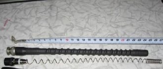
Quarter-wave transmitting antenna mast.
Also on topic:
ELECTROMAGNETIC RADIATION
The main coverage area of a broadcast station is "served" by surface (ground) wave. In order for a wave to propagate near the earth's surface, it must have vertical polarization, i.e. the radiation electric field vector must be vertical, and hence a vertical antenna is required. In reality, it is sufficient to have only a half-height antenna; the reason for this is its mirror charge.
When an electromagnetic field encounters a conducting plane on its path, it is specularly reflected from it. Therefore, the electromagnetic field created above a conducting plane by a certain system of currents and charges turns out to be identical to the field that would exist if instead of a conducting plane there was a mirror-reflected system of currents and charges, i.e. simply a mirror image of the real system in a given plane. Thus, the field above the plane is the field of a vertical half-wave symmetrical vibrator (Fig. 1). Such a vibrator radiates most intensely in a plane perpendicular to its axis; in the case under consideration, this means that the radiation is directed along the earth's surface. In practice, such an antenna is a steel mast with a height of about a quarter of the wavelength, mounted on support insulators (Fig. 2). The earth is made a good conductor by burying a system of wires in it, diverging in radial directions from the base of the antenna. If the antenna mast is equipped with guy wires for stability, then they must be divided into sections with insulators that are short enough so that the influence of the guy wires on the local field of the antenna is insignificant.
Reflection and inversion
When waves propagate from one medium to another, some of the incident energy is reflected. Depending on the properties of the media's materials, waves may be inverted upon reflection.
Imagine a long spring tied to a post. If you lightly hit a spring from the left, the disturbance will spread along the entire length of the spring until it hits the post; and at that moment it will change direction and begin to spread back to you on the other side, to the right. This is inversion.
Wave inversion upon reflection
Take the same spring and tie it to a rope looped around a post. If you lightly hit the spring from the left, the disturbance will spread along the entire length of the spring until it hits the rope; at this point it will change direction and begin to spread back towards you from the same side, to the left.
No inversion when reflected
Understanding the reflection of spring vibrations will help us understand what is happening inside the antenna.
Here are four situations to help illustrate the concepts of reflection and inversion.
Whether or not a wave is inverted upon reflection is determined by the properties of the media on both sides of the interface.
If the wave is inverted upon reflection and we want constructive interference in a rope, we must have a rope that is half a wavelength, a full wavelength, or one and a half wavelengths long, and so on:\(L = n {\lambda \over 2} \), where n is a positive integer.
Antenna resonance is based on the same principles of reflection and interference: choose the length of the wire so that the reflected energy can interfere constructively, creating a larger signal rather than reducing it.
Beam width 3 dB
This beamwidth (or half power beamwidth) of the antenna is usually determined for each of the principal planes. The 3 dB beamwidth in each plane is defined as the angle between the main lobe points that are reduced from the maximum gain by 3 dB. The 3 dB beamwidth is the angle between the two blue lines at the polar site. In this example, the 3 dB beam width in this plane is about 37 degrees. Wide beamwidth antennas typically have low gain, while narrow beamwidth antennas have higher gain.
Thus, an antenna that directs most of its energy into a narrow beam in at least one plane will have higher gain. The forward-to-backward (F/B) ratio is used as a merit metric that attempts to describe the level of radiation from the back of a directional antenna. Basically, the front-to-back ratio is the ratio of the peak gain in the forward direction to the gain 180 degrees behind the peak. Of course, on a DB scale, the front-to-back ratio is simply the difference between the peak gain in the forward direction and the gain 180 degrees behind the peak.
Standing waves
When two waves of the same length propagate in the same medium but in opposite directions (shown in blue and orange in the examples below), they can interact and form a standing wave (shown in green in the examples below). Standing waves are so called because while blue waves move to the left and orange waves move to the right, green standing waves have no visible movement in either direction.
The incident wave (orange) and reflected wave (blue) combine to form a standing wave (green)
A standing wave occurs only under certain conditions in the medium, which are determined by the mode of reflection and the length of the incident wave.
Beer can antenna
Even though it doesn't look serious, the image becomes much better. Tested many times. Try it!
Outdoor antenna made from beer cans
Needed:
- two tin cans with a capacity of 0.5 liters,
- a piece of wood or plastic about 0.5 meters long,
- piece of television wire RG-58,
- soldering iron,
- flux for aluminum (if the cans are aluminum),
- solder.
How to make an antenna from cans
We collect it like this:
- We drill a hole (5-6 mm in diameter) in the bottom of the jar strictly in the center.
- We pull the cable through this hole and take it out through the hole in the cover.
- We fix this can on the left on the holder so that the cable is directed to the middle.
- We pull the cable out of the can by about 5-6 cm, remove the insulation by about 3 cm, and disassemble the braid.
- We trim the braid, its length should be about 1.5 cm.
- We distribute it over the surface of the can and solder it.
- The central conductor sticking out 3 cm needs to be soldered to the bottom of the second can.
- The distance between the two banks must be made as small as possible and fixed in some way. One option is duct tape or duct tape.
- That's it, the homemade UHF antenna is ready.
Terminate the second end of the cable with a suitable plug and plug it into the required socket on the TV. This design, by the way, can be used to receive digital television. If your TV supports this signal format (DVB T2) or has a special set-top box for your old TV, you can receive a signal from the nearest repeater. You just need to find out where it is and point your television antenna there, made with your own hands from tin cans.
Simple homemade antennas can be made from tin cans (beer or beverage cans). Despite the frivolity of the “components,” it works very well and is very easy to manufacture
The same design can be adapted to receive VHF channels. Instead of 0.5 liter jars, use 1 liter jars. Will receive MV band.
Another option: if you don’t have a soldering iron, or you don’t know how to solder, you can do it easier. Tie two cans at a distance of several centimeters to the holder. Strip the end of the cable by 4-5 centimeters (carefully remove the insulation). You separate the braid, twist it into a bundle, and make a ring out of it, into which you insert a self-tapping screw. Make a second ring from the central conductor and thread a second screw through it. Now at the bottom of one can you clean out (with sandpaper) a spot to which you screw the screws.
In fact, for better contact, soldering is needed: it is better to tin and solder the braid ring, as well as the point of contact with the metal of the can. But it also works well with self-tapping screws, however, the contact periodically oxidizes and needs to be cleaned. When it starts snowing you will know why...
You may be wondering how to make a barbecue from a cylinder or barrel, you can read about it here.
Standing Wave Ratio (SWR)
Standing waves of maximum amplitude occur at a very precise combination of frequency (or wavelength) and antenna length.
Unfortunately, it is impractical and in fact impossible to have antennas that have the exact length required to form an ideal standing wave in the required frequency range. Fortunately, this is not necessary. An antenna with one fixed length can operate over a small frequency range with a small, acceptable level of detuning.
Standing waves and voltages in a line shown during an oscillation period
The antenna length must be adjusted to produce a standing wave as close to ideal as possible at the center of the operating frequency range.
SWR (standing wave ratio) meters measure the ratio of transmitted energy to reflected energy, and this ratio should be as close to 1:1 as possible.
Small adjustments can be made by adding passive components to the circuit between the final gain stage and the antenna. Small deficiencies in antenna tuning can cause a potential difference to appear at the final amplification stage, heating the final section of the transmission line. A large imbalance can cause a large potential difference to be applied back to the transmitter circuit, causing dielectric breakdown, arcing and failure of the final amplifier.
Manufacturing a log-periodic television antenna
Logoperiodic TV antenna
The “speech therapy” antenna is a receiving line (a pair of metal tubes) with halves of linear dipoles perpendicularly connected to it - pieces of conductor with a diameter of a quarter wave of the working signal. The length and distance between the latter varies exponentially.
To manufacture a log-periodic antenna, it is necessary to perform a number of calculations:
- The calculation of the length of the dipoles begins with the second longest one.
- Taking the reciprocal of the progression index, the length of the longest dipole is calculated.
- Next, it remains to calculate the shortest - the first - dipole, and then, based on the selected frequency range, the length of the “zero” dipole is accepted.
LP antenna parameters
To achieve maximum reception power, there must be a distance between the dipoles of 0.03-0.05 wavelengths, but not less than double the diameter of any of them.
The length of the finished LP antenna is about 400 mm. The diameter of the base of the LP antenna should be 8-15 mm, and the gap between their axes of the receiving line should be no more than 3-4 dipole diameters.
Homemade LP antenna
For normal operation of the LP antenna, you need to select a high-quality and fairly thick (about 6-8 mm in sheath) coaxial cable. Otherwise, you will not be able to compensate for the attenuation of decimeter waves, as a result of which the television tuner will be unable to sense the signal.
The cable to the receiving line cannot be secured from the outside, as this will sharply reduce the quality of signal reception.
When installing such an antenna, you need to ensure its wind resistance, and if you use a metal pipe as a mast, you need to install a dielectric insert - a wooden block - at least 1.5 cm long between it and the receiving line.
You can improve the design of an LP antenna by installing linear or fan-shaped hangers of a meter field on it. This system is called “delta”.
Delta antenna circuit
Transfer of information
Probably the two most well-known methods of transmitting information are frequency modulation (FM) and amplitude modulation (AM).
Frequency modulation
With frequency modulation, information is transmitted by changing the frequency of the carrier wave.
Frequency modulation
Amplitude modulation
With amplitude modulation, the frequency of the carrier wave remains constant. Information is transmitted by changing the amplitude of the carrier.
Amplitude modulation
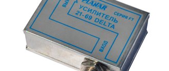
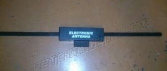
Selecting an antenna for your TV
Source nastroyvse.ru
I think that you have an excellent understanding of the differences between active and passive receiving devices, although I did not go into details of their configuration, but that is another topic. When choosing, you can focus on the following parameters:
- Distance to repeater. If you don’t know where the TV tower is, use the CETV map, which can be easily found via Google or a Yandex search engine. In the case when the TV tower is located closer than 15 km to your home, there is simply no point in using an amplifier.
- Where is the antenna installed? The signal strength drops if you live in a dry lowland or in a low building among multi-story buildings and there is no way to direct the antenna to the repeater across an open space. Here, of course, the active option is more suitable.
- Power level. The proverb says that everything is good in moderation, and so it is here. When the signal is too strong, the tuner will not be able to read it. Here you will need an injection unit.
- If this is a building where there are many televisions, for example, a hospital, then a passive device will not be enough even with a good signal - you will have to install several antennas. In such cases, it is easier to use a gain block.
Dipole antenna
A simple antenna that uses two identical elements is called a dipole. The shortest dipole antennas operate with oscillations for which the antenna length is equal to half the wavelength, and which creates standing waves along the entire length of the antenna.
Standing waves in a dipole antenna
Varying electric fields along the length of the antenna create radio waves that travel in directions away from the antenna.
Antenna emitting energy
Antennas make it possible to transmit and receive information by interacting with and being affected by the electromagnetic fields that permeate the universe. In the next article we will look at the different types of antennas and how they work.
Original article:
- Mark Hughes. An Introduction to Antenna Basics
How to make a powerful antenna with your own hands
We make 2 rhombuses from any metal that conducts electricity and connect them at the corners, and a reflector is attached behind them in order to get rid of interference.
The best metal for a DIY Kharchenko antenna is copper or aluminum wire measuring 3 - 6 mm in diameter.
To connect a digital antenna and receive a signal on a digital TV, you need a coaxial cable of the required size.
DIY Kharchenko antenna
A little theory
Operating principle of an antenna for digital packet television
Any television signal propagates in space from the emitters of the transmitting television tower to the TV antenna by an electromagnetic wave of a sinusoidal shape with a high frequency, measured in megahertz.
When an electromagnetic wave passes through the surface of the receiving beams of the antenna, a voltage V is induced in it. Each half-wave of a sinusoid forms a potential difference with its own sign.
Under the influence of an induced voltage applied to a closed receiving circuit of the input signal with resistance R, an electric current flows in the latter. It is amplified and processed by the digital TV circuit and output to the screen and speakers as image and sound.
For analog models of TV receivers, an intermediate link works between the antenna and the TV - a DVB-T set-top box, which decodes digital information of an electromagnetic wave into a normal form.
Vertical and horizontal polarization of digital TV signal
In television broadcasting, state standards require electromagnetic waves to be emitted in only two planes:
- verticals;
- horizontal.
In this way, transmitters send emitting signals.
And users simply need to rotate the receiving antenna in the desired plane to maximize the power potential.
Requirements for a digital packet television antenna
TV transmitters propagate their signal waves over short distances, limited by the line of sight from the top point of the TV tower emitter. Their range rarely exceeds 60 km.
For such distances, it is enough to provide a small power of the emitted TV signal. But, the strength of the electromagnetic wave at the end of the coverage area should form a normal voltage level at the receiving end.
A small potential difference, measured in fractions of a volt, is induced at the antenna. It creates currents with small amplitudes. This imposes high technical requirements on the installation and quality of manufacturing of all parts of digital reception devices.
The antenna design should be:
- manufactured carefully, with a good degree of accuracy, eliminating loss of electrical signal power;
- directed strictly along the axis of the electromagnetic wave coming from the transmitting center;
- oriented according to the type of polarization;
- protected from extraneous interference signals of the same frequency coming from any sources: generators, radio transmitters, electric motors and other similar devices.
Indoors[edit]
A very common indoor antenna is the “bunny ears”. This model also has a loop antenna for UHF reception.
Indoor antennas can be mounted on the TV itself or placed on a table next to it, connected to the TV using a short feeder. Due to space constraints, indoor antennas cannot be as large and complex as outdoor antennas, and they are not mounted at the same height; For these reasons, indoor antennas generally do not provide as good reception as outdoor antennas. They are often quite sufficient in urban and suburban areas which are usually within the strong radiation "footprint" of local television stations, and in rural areas reception fringes only an outdoor antenna can provide adequate reception. Some of the simplest indoor antennas are described below, but there is a wide variety of designs and types. Many have a dial on the antenna with a number of different settings to change the antenna's reception pattern. It should be rotated with the device turned on while looking at the screen until the best image is obtained.
Bunny ears[edit]
The oldest and most widely used indoor antenna is the rabbit ears.
or
rabbit ears
, which often come with new televisions. It is a simple half-wave dipole antenna used to receive the VHF television bands consisting in the US of 54 to 88 MHz (Band I) and 174 to 216 MHz (Band III), with wavelengths ranging from 5.5 to 1.4 m. consists of two telescopic rods attached to the base, which are about 1 meter long (about a quarter wavelength at 54 MHz) and can be folded when not in use. For best reception, the rods should be tuned to slightly less than 1/4 of the wavelength of the frequency of the received TV channel. However, the dipole has a wide bandwidth, so adequate reception is often achieved without length adjustment. The half-wave dipole has a low gain of about 2.14 dBi; this means it is not as directional and sensitive to distant stations as a large rooftop antenna, but its wide-angle reception pattern can allow it to receive multiple stations located in different directions without having to retune when changing channels. Dipole antennas are bidirectional, meaning they have two main lobes in opposite directions, 180° apart. Instead of being fixed in position like other antennas, the elements are mounted on hinges and can be adjusted to different angles in a "V" shape, allowing them to be moved in crowded areas. Another reason for the V-shape is that on high-band receiving channels with fully extended rods, the antenna elements tend to resonate at their 3rd harmonic. In this mode, the direction of maximum gain (main lobe) is no longer perpendicular to the bars, but the radiation pattern will have the lobes angled to the bars, giving the ability to adjust them to different angles.
Whip antenna [edit]
Some portable televisions use a whip antenna. It consists of a single telescopic rod, about a meter long, attached to the TV, which can be removed when not in use. It operates as a quarter-wave monopole antenna. The other side of the feed line is connected to the ground plane of the TV circuit board, which acts as a ground plane. A whip antenna typically has an omnidirectional reception pattern with maximum sensitivity in directions perpendicular to the antenna axis and a gain similar to a half-wave dipole.
Loop antenna[edit]
UHF channels are often received with a single-turn loop antenna. Since the rabbit ears antenna only covers the VHF bands, it is often combined with a UHF loop mounted on the same base to cover all TV channels.
Flat antenna [edit]
Soon after television broadcasting switched from analog to digital, home antenna marketing expanded beyond the traditional "bunny ears." Flat antennas are lightweight, thin, and typically square in shape to provide more omnidirectional reception. [ citation needed
] They connect to TVs using coaxial cable only;
they may also be sold with a signal booster that requires a power supply. Inside, the thin, flat square is a loop antenna with round metal wiring embedded in conductive plastic. [ citation needed
]
Instructions for assembling the best antennas
You can assemble many interesting and effective antennas with your own hands. Let's look at detailed instructions for making the best and easiest to make models.
Homemade #1 - simple TV antenna
If the repeater is located within 30 km from the dacha, then the most common design, assembled from two tubes and a cable, will do. The wire is connected to the corresponding TV input jack.
Layout and selection of materials
A typical device for a primitive country antenna is shown in the figure below. It can be seen that two tubes of the same length are joined on a plate, which in turn is fixed to the mast.
A pipe signal catcher can be made in a couple of hours. The work does not require any qualifications of the performer or the presence of expensive tools
The first thing you need to do is find out the broadcast frequency of the local TV tower - the length of the pipes depends on the parameter.
Broadcast band range – 50-230 MHz. Each channel requires its own length of antenna “whiskers”.
The table shows the design parameters of the signal catcher based on the frequency of the broadcasts. The broadcast band is divided into 12 channels
Pipes made of duralumin, steel, and brass are suitable for making an antenna. Their diameter can vary between 8-24 mm, most often they take 16 mm. The main condition is that the sections must be equivalent, prepared from pipes with the same properties.
Necessary materials:
- metal pipe - a cut 6 cm shorter than the length determined from the table values;
- wire with a resistance of 75 Ohms , the required length is the distance from the TV to the antenna plus 2 m for sagging and matching loop;
- thick electrical insulating getinax - thickness from 4 mm;
- metal strips , clamps for fixing pipes on a plate;
- mast for the antenna - this can be a corner; if the height is small, it is permissible to use a wooden block.
For work, it is advisable to stock up on a soldering iron, solder, and flux. It is recommended to solder the connections of the central conductors - this will extend the life of the device and improve image quality.
To protect against oxidation, the joint areas must be filled with silicone or epoxy resin. An affordable, but not reliable way is to wrap it with electrical tape.
Assembly and configuration of the invention
First, cut the required size of the pipe and saw it into two equal parts. You can use metal cutters.
The next step is to flatten the tubes on one side for easy attachment to the holder. The pieces are applied to the getinax and fixation points are marked.
The distance between the inner ends of the tubes is 6 cm, between the outer ends - the distance indicated in the table.
Subsequent work progress:
- Secure the antenna whiskers to the holder with clamps, and fix the getinax plate itself on the mast.
- Connect the pipes through a matching device - cable loop type RK-1,3,4. The element parameters are displayed in the right column of the table, the manufacturing principle is shown in the antenna design diagram.
- Solder the central cores to the ends of the tubes, connect the braid with a piece of a similar conductor.
- Connect the central conductors of the ends of the matching loop to the television cable. Connect the braid with copper wire.
- Fix the loop and the downward wire on the rod.
- Raise the mast to the roof of the country house and adjust the antenna.
Two people are needed to determine the optimal position of the device. The first rotates the antenna on the street, and the second monitors the change in the image on TV.
To quickly set up, you can check with your neighbors on which side of the house the receiver is located and where the vibrators are directed
Having detected good signal quality, the structure is fixed in the selected position.
Homemade #2 - loop antenna made from pipe
The module is a little more difficult to create, but it expands the reception radius to 40 km. The main difficulty lies in the need to bend the pipe.
The bending radius does not have a special role. The main requirements for the device: the distance between the inner ends is 65-70 mm, the evenness and symmetry of the arrangement of the wings
The length of the cable and pipe is calculated based on the broadcast frequency of TV channels.
Blanks are made to suit the required parameter - the vibrator and the wire for the matching device are measured and cut. The recommended pipe diameter is 12-18 mm.
Table values for the correspondence between channel frequency and signal catcher parameters. For example, with an airwave indicator of 93.25 MHz, the length of the pipe should be 151 cm, and the length of the matching cable should be 104 cm
Assembly begins by bending the pipe. The edge of the vibrator is flattened and sealed. The pipe is filled with sand, and the second end is sealed in the same way as the first. The edges can be sealed by placing the plugs on silicone.
The shaped pipe is attached to the mast. Matching loops are screwed and soldered to the ends of the vibrator, and the television cable is fixed. Secure the braid with copper wire and begin setting up.
Homemade #3 - Kharchenko signal catcher
The figure-of-eight or zigzag television antenna is suitable for DVB-T2 digital television, broadcasting in the UHF range. The module is easy to manufacture. To implement the project, you will need conductive metal.
Calculation and drawing development
The design of the TV antenna is very primitive - two squares/diamonds fastened together. In the original design, the Kharchenko module provides for a reflector located behind the figured elements.
A field of metal strips is required for analog signals. Digital television reception is possible without a reflector. The field can be developed later if the reception is poor
To make a zigzag antenna, it is not necessary to calculate the wavelength. It is advisable to build a structure with more broadband - this will increase its capabilities.
If desired, you can calculate the device parameters. Divide the wave value of the transmitted signal by 4 - the resulting value is the side of the square.
There should be a small distance between the two parts of the TV antenna. To maintain the gap, it is enough to make the outer sides longer and the inner sides shorter. Length of sides (B1 and B2) - at your discretion
The example shown shows a drawing of an antenna with side parameters: B1 - 14 cm, B2 - 13 cm. The difference in lengths of one centimeter gives the required distance between the squares.
The lower sections are extended by 1 cm. This gap is necessary for the loop for soldering the antenna cable.
Frame making and cable preparation
Subsequent calculations will be given in relation to the data in the drawing shown above. The total perimeter of the squares is 112 cm. You should cut the wire to the required length and form the part according to the diagram.
Work order:
- Bend the wire in the middle at a right angle.
- Next come two sections of 14 cm each, followed by sides of 13 cm each. After each bend, we check the evenness of the corners, it must be strictly 90 degrees.
- When the first square is formed, begin to create the second figure. Again there are versatile elements of 14 cm each, and behind them are two parts of 13 cm + 1 cm.
Minor differences in side lengths are acceptable. The main thing is to maintain right angles.
If the molding of the structure is done correctly, then between the two parts of the TV antenna there should be a distance of 1.5-2 cm
The next step is preparing the cable. It is cleaned on both sides. An incision is made along the circumference of the cable, 2-2.5 cm from the edge.
The work is done carefully so as not to damage the inner braid. Along the cut line, the cable is slightly broken and the insulation is removed.
The braid and foil must be twisted into a bundle. You should get two conductors: a central monocore and a twist. Both elements must be tinned. The wire should stick out 2 cm, cut off the excess
Solder the plug on the other side of the cable. The wire must be cleaned to 1 cm, the conductors must be formed and tinned.
In areas where soldering is performed, clean the plug with sandpaper and wipe with alcohol. Solder a monocore to the central output, and a twist to the side output. Crimp the grip around the insulation, screw on the plastic tip, or alternatively, fill it with non-conductive sealant. Before the composition dries, assemble the plug.
The order of connecting elements
The final stage of assembly is the joining of the frame and cable. If there is no connection to a specific channel, then it is better to do the soldering at the midpoint to expand signal capture.
The cut end of the cable is connected to the two sides of the square in the center. Before final fixation, you can check the performance of the antenna. If everything is normal, then seal the soldering area.
The most reliable method is to fill it with silicone or glue. A plastic lid from a five-liter eggplant is suitable for the case.
Holes are made in the mini-container for the square elements, a frame with a wire is placed and filled with a sealing compound.
Homemade product #4 – “double square” antenna
The narrowband design will solve the problem of a weak signal or clogging of the broadcast with a stronger broadcast. The antenna is also suitable for receiving digital television. The main condition for operation is a clear orientation towards the signal distributor.
Device diagram and dimensions
Structurally, the TV antenna is presented in the form of two frames connected at the top and bottom by arrows. The large square is a reflector, the smaller one is a vibrator.
A variation with three frames is possible, providing a high signal gain. Least square – director
The upper boom is made of metal, and the lower one is made of getinax, textolite or other insulating material.
Requirements for the TV antenna device:
- the centers of the squares must be on the same line, this straight line faces the transmitter;
- the smaller frame has an open contour, the ends are fixed to the textolite plate;
- The upper part of the mast for the antennas is made of wood.
The parameters for the manufacture of two-element frame television antennas are taken from the table. The dimensions of the working elements depend on the type of waves: decimeter or meter.
Explanations for the table: B – side length of the smaller square, P – value of the larger frame, A – distance between two elements, W – loop in a short-circuited bridge
In a three-frame design, the distance between the ends of the middle frame is increased to 5 cm.
Assembly and connection
To connect the frame to the antenna cable, you will need a balun short-circuited cable. The device is constructed from sections of antenna wire.
The right element is a cable, the shortened left one is a feeder. A television cable is attached to the place where they are connected. The length of the segments is determined from the table, taking into account the wavelength of the signal.
Before assembling the elements, they are cleaned. The aluminum layer is removed from the cable and the braid is twisted into a bundle. The central conductor is cut off
The same actions are performed with the feeder, leaving the cable core.
Further sequence of work:
- Solder the central core of the feeder and the cable braid to the left end of the vibrator.
- Attach the feeder twist to the right end of the active frame.
- Connect the bottom of the cable to the feeder braid with a metal jumper. Solder the harnesses with low-melting solder.
- The cable sections must run parallel, the distance is 5 cm. To fix the distance, dielectric material is used. The matching device is mounted on a textolite plate.
- Solder the television cable to the bottom of the feeder, joining the corresponding elements - braid to braid, rod to rod.
The use of a matching device reduces the likelihood of interference and eliminates the double image effect. You cannot do without it if you are at a significant distance from the transmitter.
Homemade #5 - TV antenna made from tin cans
The original design of the antenna using improvised means significantly improves the signal quality. This option is suitable for a dacha in the suburbs, not far from a TV tower.
To create a primitive device you will need: 2 beer cans of 0.5 or 0.75 liters, self-tapping screws, a 3-5 m television cable, a screwdriver, a soldering iron, tin, a wooden pin or hanger, and electrical tape.
Subsequent actions can be divided into several stages.
Preparing the cable and making contacts
When preparing the cable, clean the insulation by retreating 10 cm. Divide the cable into two conductors - the central core and the braided twist. At the other end of the cable you need to install a regular plug.
When making contacts, the twisted cable screen is fastened to one can, and the copper core to the other. Self-tapping screws are suitable for fixing.
To obtain a better image, it is better to strengthen the fastenings by soldering. Connections must be sealed
Assembling a homemade structure
During assembly, it is necessary to make a supporting structure for the signal receiver. In the simplest version, you can use ordinary coat hangers. A wooden stick will also work.
The cans are fixed to the mast with adhesive tape or electrical tape, the structure is lifted onto the roof and the setup begins, selecting the optimal location for the improvised antenna.
When working, you must use containers with a smooth surface; ribbed materials are not suitable. The jars are pre-washed and dried.
The nuances of making signal catchers
When starting to make a homemade device, you need to have an idea of the possible design options and the rules for their assembly.
The entire variety of television antennas is usually divided into several types:
- All-wave . A frequency-independent antenna is the cheapest and easiest to manufacture. The base is a metal frame, and tin containers or beer cans are used as receivers. The design does not have high performance parameters, but it is quite suitable for a summer residence if the broadcast tower is located nearby.
- Log-periodic . The principle of operation is comparable to a fishing net that sorts prey during catching. The device is easy to manufacture, and its parameters exceed those of all-wave models. The antennas are consistent with the feeder in any range.
- Decimeter . Designs that function well regardless of reception conditions. Various designs are possible: zigzag, diamonds, circle, etc.
The antenna parts through which the useful signal currents run are joined by welding or soldering. However, when placing the device on the roof of a house, such contacts will be corroded over time by corrosion.
One of the conditions for sufficient purity and stability of reception is the minimum number of joints in the design of the signal catcher
In addition to this norm, when creating an antenna for a summer residence with your own hands, it is advisable to adhere to the following rules:
- The central core and braid are made of inexpensive alloys that are resistant to corrosion processes. However, they are difficult to solder - work is carried out with extreme caution so as not to burn the wire.
- To connect elements, you need to use a 40 W soldering iron, flux paste, and low-melting solder.
- It is not advisable to use aluminum wire to create structural parts. The material quickly oxidizes, losing its ability to conduct a signal. The best option is copper, an affordable alternative is brass.
The receiving area of the catcher must be large. In order to increase it, metal rods can be symmetrically attached to the frame that filters out ethereal noise.
Connecting the simplest signal amplifier to the antenna will significantly improve the quality of broadcast transmission. Factory products are already equipped with this element
A tandem of a homemade antenna and amplifier will provide the necessary receiving power. It is enough to take the structure onto the roof and install it in the direction of a nearby television tower.