A transformer, as an element of radio engineering and electrical engineering, operates on the basis of electromagnetic induction. When talking about the inductance of a transformer, we mean the inductance of the windings and the mutual inductance between them.
Each of the windings represents a number of turns of wire wound around a ferromagnetic core, that is, an ordinary inductor.
The difficulty in determining the coil parameters is that they vary depending on several parameters and their combination:
- currents in windings;
- magnetization level of the magnetic circuit;
- magnetic characteristics of the core;
- interaction between adjacent windings;
- presence of a constant current component.
Design and principle of operation of a power transformer
The design of any transformer is based on the following elements:
- Core made of ferromagnetic material.
- Primary and secondary windings. In the case of an autotransformer, one winding performs both functions.
In AC networks of industrial frequency (50 or 60Hz), steel processed using special technology is used as a ferromagnetic material. At high frequencies, transformers are often made without a core, since the interconnection between the coils is sufficient for normal operation.
Principle of operation:
- an alternating electric field is created in the primary winding connected to the power circuit;
- under the influence of the field of the primary coil, an alternating magnetic field is created in the core;
- Due to electromagnetic induction, an induced emf is observed in all windings.
The induced emf in the primary winding is directed opposite to the applied voltage, so they cancel each other. As a result, when there is no load, a relatively small no-load current flows through the primary winding.
The presence of a secondary circuit current similarly causes an additional magnetic flux, and this is the self-induction emf in the primary coil. As a result, the primary voltage compensation decreases and the current in the primary circuit increases.
Contents Previous § Next
Chapter fourteen TRANSFORMER EQUIPMENT DIAGRAM AND ITS PARAMETERS
§ 14-1. Transformer winding inductances and electromagnetic dissipation
Winding inductance.
In transformers with a steel core, the magnetic permeability of steel is c.
during the magnetization reversal cycle is not constant. Therefore, during this cycle, the own L
and mutual
M
inductances of the transformer windings are also variable.
As a result of such inconstancy μ,
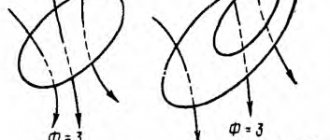
when a transformer is connected to a network with a sinusoidal voltage, higher harmonics arise in its magnetizing current f'o (see § 13-1).
When the transformer operates at current i0
a load current is superimposed, in relation to which the current j0 and, in particular, its higher harmonics are small. Therefore, when studying the operating modes of a transformer, the indicated harmonics can be neglected and only the fundamental current harmonic /0 can be taken into account. This is equivalent
assumption that during the magnetization reversal cycle μ, L
and
M
are constant.
The influence of core saturation can be taken into account by taking into account at different operating modes of the transformer, at different core flux amplitudes, the values of (q, L
and
M
for a given operating mode. In accordance with the above, we will assume that
q, L
and
M
are constant .
Let's consider the inductance and inductive resistance of the windings, caused by the magnetic flux of the core Fs, all the power lines of which are completely closed along the closed core and therefore interlock with all turns of the primary and secondary windings (Fig. 14-1).
The picture of the magnetic field, which is closed entirely along the core, is the same regardless of which of the windings this field is created. Therefore, the magnetic resistance to the flux Fc is the same for the field of both windings and equalities (14-4), (14-5) and (14-6) include the same value /? cC. Due to this also
The first terms of equalities (14-9) and (14-10) are significantly larger than the second ones, since the flows through the air are relatively small.
The concept of electromagnetic scattering. The completeness of electromagnetic coupling of two inductively coupled circuits is characterized by the coupling coefficient of these circuits
As is known from the course of theoretical foundations of electrical engineering, in real conditions there is always
< 1.
If there were no flows Fv1 and Fv2 in the transformer, closed through the air, then Lu -
Lcl, L22 = Lc2,
M -
Me, and in this case, in accordance with equalities (14-4), (14-5), ^14-6) and (14-11)
Thus, the incompleteness of the electromagnetic connection in the transformer, expressed by the inequality c < 1, is due to the presence of fluxes Fv1 and Fn2 or, more precisely, their unequal coupling with both windings. Condition with
- 1 would be achieved only if it were possible to completely combine the primary and secondary windings, which is virtually impossible.
The phenomenon of incomplete electromagnetic coupling is called electromagnetic scattering.
Along with relation (14-11), it is advisable to introduce into consideration the electromagnetic scattering coefficient
The less with
and the larger
a,
the greater the scattering.
Due to the fact that the phenomenon of scattering is caused by the unequal or incomplete adhesion of the flows Fv1 and Fv2 passing through the air with both windings, these flows are often also called leakage fluxes, but this name is to some extent arbitrary, since the flows Fv1 and Fv2 also cause the phenomenon of mutual induction , since Mv F
0. As will be explained below, the degree of incompleteness of electromagnetic coupling, or the amount of electromagnetic scattering, has a great influence on many
technical indicators and characteristics of transformers and rotating electrical machines.
In transformers with a ferromagnetic core, the fluxes FV1 and Fv2 are relatively small.
I Therefore, electromagnetic coupling in transformers is very high, and dissipation is low.
In power transformers, for example, with
= 0.998 -*- 0.9995 and, accordingly, o = 0.001 h- 0.004.
As a result , the value of a
determined by formula (14-12), is the difference between very close values and the calculation of a using this formula is associated with very large errors, since
Ln, L%%
and
M in
practical devices cannot be calculated or determined from experience with sufficient higher degree of accuracy. Therefore, there is a need to directly determine the parameters characterizing electromagnetic scattering.
§ 14-2. Transformer Voltage Equations
The operating process of a transformer can be studied based on the voltage equations of its windings.
Capacitive currents between the winding elements (turns and coils) and between the windings and the transformer core under normal transformer operating conditions (f
< 1000 -f- 5000
Hz)
are very small and can be neglected.
In transformers without a ferromagnetic core, Ln,
L22 and
M
are constant. In accordance with what is stated in § 14-1, it can be assumed that these values are also constant for any considered operating mode of a transformer with a steel core. Let us first neglect magnetic losses in the core. Then for a single-phase two-exchange
accurate transformer (Fig. 14-2), the following voltage equations in differential form are valid:
Rice. 14-2. Diagram of a single-phase two-winding transformer
Here iъ и.2, ilt i2
— instantaneous values of voltage and current of the primary and secondary windings;
rx, g.g, Lu,
L22 - active resistance and self-inductance of the windings;
M
is the mutual inductance of the windings.
In the diagram Fig. 14-2 indicates positive directions and
and
i,
and the arrow
and
is directed from the point with the highest potential to the point with the lowest potential.
When composing equations (14-13), the primary winding is considered as a receiver, and the secondary winding as a source of electrical energy, and these equations themselves are interpreted as follows.
Their primary tension
is applied, is spent on the voltage drop r^ and balancing e. d.s. primary winding
and therefore consists of two components: rxix
and -
ex,
which is expressed by the first equation (14-13).
Secondary voltage and%
arises due to induction in the secondary winding e. d.s.
which corresponds to the second equation (14-13). In equations (14-13) it is assumed that M
> 0 and positive currents
ix
and
i2
create flows of the same direction in the core.
Note that on the right side of the second equation (14-13) the signs could be reversed. Then u2 should be interpreted as the voltage applied to the secondary winding from the side of the secondary network. Some, especially foreign, authors also use this latter form of notation.
Typically, power transformers, as well as a number of types of special transformers, operate with sinusoidally varying currents and voltages. In this case, instead of differential Equations (14-13), it is more convenient to use complex equations for the effective values of currents and voltages. To obtain these equations, one should substitute into equations (14-13)
xn — (nLu; xn
= col22; dg12 = soM (14-15)
represent the total self- and mutual inductive resistance of the windings.
With a symmetrical load of three-phase transformers, electromagnetic processes occur in all phases in the same way and the corresponding electromagnetic quantities in each phase are also the same and are only shifted in phase by 120°. Some asymmetry of the magnetic circuit of a three-leg transformer, as well as the appearance in some cases (see § 13-1) of third flux harmonics usually do not have a noticeable effect on the operation of the transformer under load. In addition, these phenomena can be taken into account separately if necessary. For these reasons, equations (14-14) are also applicable with great accuracy* to the phase quantities of a three-phase transformer with a symmetrical load. The system of equations (14-14) does not take into account only losses in the steel of the transformer core. Accounting for these losses will be considered separately.
For a three-phase transformer in accordance with the above 0it U2,
/x and /2 represent the phase values of voltages and currents.
Equations (14-13) and (14-14) completely define the processes occurring in the transformer under the above assumptions and allow you to solve problems related to the operation of the transformer. For example, if you determine /x from the first equation (14-14) and substitute its value in second equation (14-14), then we obtain the dependence of the secondary voltage 0%
from the load current
1g:
and the second term is the voltage drop at the secondary terminals npij load.
From these relationships it is clear that such important quantities from an operational point of view as voltage drop and short-circuit current are determined by a small fraction of a
total inductive reactance dg22 due to electromagnetic scattering. The same can be said about a number of other great things that characterize the operational properties of transformers and rotating electrical machines. Therefore, determining the quantities characterizing electromagnetic scattering is an important task in the theory of electrical machines.
In addition to the above considerations about the accuracy of the results, calculations based on equations (14-13) and (14-14) are also inconvenient due to the fact that due to the inequality of the numbers of turns (w1 Ф
to2) parameters
rlt
r2,
bp,
L22,
M, хп,
х22 and
х12,
as well as voltages
уь у2, Ult Uz
and currents i2, /1( /2 vary greatly in magnitude.
In connection with the above, it is advisable to develop the theory of electric machines in relation to the issues under consideration in the following closely related directions:
1. Inductively coupled windings are brought by appropriate conversions to the same number of turns, as a result of which the orders of voltages, currents and parameters of these windings become respectively the same.
2. From the total inductances Ln,
/_22 and inductive resistances of self-inductance
xn
and x22 components are distinguished - leakage inductance
Si}
S2 and leakage inductive resistances
xx
and
x%,
due to the phenomenon of electromagnetic scattering, and this selection is made in such a way that the remaining parts of the total inductances (Lu -
Si,
L22 - S2) and inductive reactances
(xc
-
xx22
-
xy)
correspond to inductively coupled circuits with complete coupling
(c =
1).
3. Direct methods are being developed for calculating small parameters - inductances and leakage inductive reactances - regardless of the calculation of total inductances and inductive reactances, thereby achieving the necessary accuracy in determining these small parameters.
4. From electrical circuits with inductive coupling, a transition is made to equivalent circuits with electrical coupling of circuits, which leads to simplified calculations and greater clarity of the theory.
5. Inductances and inductive leakage resistances are introduced explicitly into the calculated relationships and equivalent circuits, which makes it possible to calculate with the necessary accuracy quantities that depend on electromagnetic leakage.
These issues in relation to transformers are discussed below.
§ 14-3. Equivalent circuits for a two-winding transformer
Bringing the secondary winding to the primary.
Primary and secondary currents, voltages and other quantities are of the same order if the primary and secondary windings have the same number of turns. Let us therefore consider, instead of a real transformer, an equivalent so-called reduced transformer, the primary and secondary windings of which have the same number of turns.
Let us imagine that the real secondary winding of the transformer with the number of turns w2 is replaced by an imaginary, or reduced,
winding with the number of turns w\ - Wx.
In this case, the number of turns of the secondary winding will change in
once. Value k
called the reduction or transformation coefficient.
As a result of such a replacement, or reduction, e. d.s. E'2
and the voltage
U2
of the reduced winding also changes
k
times compared to the values of £2 and
U2
of the real secondary winding:
In order for the powers of the reduced and real windings to be equal in all operating modes, it is necessary to observe the equality
Where 1’%
— reduced secondary current. From here, taking into account the second equality (14-21), it follows that
The magnetizing forces of the reduced and real windings based on expressions (14-20) and (14-22) are equal to:
/>; = /ash2. (14-23)
In order for electromagnetic processes in real and reduced transformers to proceed identically, the reduced and real secondary windings must create the same magnetic fields. For this, in addition to meeting condition (14-23), it is necessary that the reduced secondary winding have the same geometric dimensions and configuration and be located in the window of the transformer core in the same way as the real secondary winding (see, for example, Fig. 12- 2, 12-26). Therefore, the total cross-section of all turns of the reduced winding should be the same as that of the real winding, and the cross-section of each turn of the reduced winding should decrease by k
once.
But since the reduced winding has k
times more turns, then, as a result, the active resistance of the reduced winding is
k2
times greater than the real one:
Since with the same geometric dimensions and the same arrangement of the coils, their inductance and inductive resistance are proportional to the squares of the numbers of turns, then between the inductive resistances of the reduced winding x'3
and real lg2 there is the same relationship:
Thus, all energy and electromagnetic relationships in the reduced and real transformers are the same, which makes it possible to carry out the indicated reduction.
Equivalent circuit without taking into account magnetic losses.
In accordance with the above, we will make the following statements in the transformer voltage equations (14-14^):
When moving to the electrical connection of two circuits, a branch common to both circuits should appear in the corresponding equivalent circuit, which flows around the sum of the currents of both circuits /r + 1[.
Accordingly, identical terms with factors (/x + /J) should appear in the voltage equations of these circuits.
From equations (14-27) it is clear that in order to obtain such terms in them, you need to add to the first of these equations and subtract from it the term ]khp!r
and add to the second and subtract from it the term
]khp{'%.
In this case we get
Let us introduce the following names and designations:
1) reduced active resistance of the secondary winding
Equations (14-34), as is easy to see, correspond to the equivalent circuit in Fig. 14-3, a.
Indeed, mentally bypassing the left and right contours of the diagram in Fig.
14-3, and
having compiled the voltage equations for these circuits, we again obtain equations (14-34). Thus, the diagram in Fig. 14-3, a is a transformer equivalent circuit corresponding to equations (14-14) and (14-34).
In a similar way, you can also transform the stress equations in differential form (14-13) by making substitutions in them
This results in the equivalent circuit shown in Fig. 14-3, b,
Where
represent the leakage inductances of the primary and secondary windings, and
— reduced mutual inductance.
Equivalent circuit fig. 14-3, b
valid for any pattern of changes in voltage and current over time, including
including in the case of transient processes.
Equations (14-34) and equivalent circuits in Fig. 14-3 can be interpreted in such a way that the resistance gh
and
хъг'ъ
and
х\
or inductances
St
and Sj are included in the db winding circuits before and after the transformer, and the parameters of the transformer windings are reduced by these values.
The result is an ideal transformer, the active resistance of which is equal to zero, and the electromagnetic coupling coefficient c = 1. Indeed, for such an ideal transformer the reduced intrinsic and mutual inductive resistances are the same and equal to x'n
=
kxn
and therefore, in accordance with equalities (14- 12) and (14-19) c2 = 1 and
a
= 0.
Rice. 14-3. Equivalent circuits for two-
winding transformer without
accounting for magnetic losses
Note that, as follows from considering the above transformations, relations (14-26) and all subsequent ones, as well as the equivalent circuits in Fig. 14-3 are fair and correctly reflect all processes in the transformer for any value of k.
From a mathematical point of view, these transformations mean a transition from the variables /72 and /2 to the new variables
O'2i 1'2
according to formulas (14-26), which is possible for any value of
k.
In this regard, it is necessary to emphasize that inductive reactances and leakage inductances, according to equalities (14-30) - (14-33), (14-36), (14-37) and (14-38), are determined ambiguously and depend from the reduction coefficient
k.
However, for power transformers
k
is rationally determined by formula (14-20), as is customary in practice and throughout this book.
Choosing a different value of k
is advisable only in special cases, for example in measuring current transformers *.
Equivalent circuit parameters.
Let's consider the parameters of the equivalent circuits in Fig.
14-3 at k
=
wjw2
[see equality (14-20)].
Reduced mutual inductance based on equalities (14-6), (14-10) and (14-38)
Therefore, resistance x'n
with great accuracy equal to the self-inductance resistance of the primary winding from the flow closed through the core.
1 A.I. Vol Dec. ABOUT
transformer equivalent circuit and its parameters.
"Electricity", 1952, no.
8, p. 21-25.
Branches 1
—
2
equivalent circuits fig. 14-3 are called magnetizing branches. The magnetizing current flowing through these branches
Thus, the leakage inductance Slt
52 and Sj and inductive leakage reactances
However, the second terms of equalities (14-42) and (14-43) cannot be neglected in comparison with the first ones, and therefore flows closed through the air can be called dissipation flows only conditionally.
Equivalent circuit taking into account magnetic losses.
Losses in the steel of the rvg core at a given frequency are proportional to the following quantities:
Thus, losses #vg are proportional to the square of the voltage Un
to terminals*
1-2
of the magnetizing circuit of the equivalent circuit Fig.
14-3, a.
If an active resistance gmg is connected to these terminals in parallel
x'p
=
xc1
, as shown in Fig.
14-4, a,
The value is ryat
for a given a.
d.s. Ex
can be considered known from calculated (see § 13-2) or experimental data. Then it can be considered known - also gmg.
Magnetizing current
is divided in two branches of the magnetizing circuit (Fig. 14-4, a) into active /mA and reactive 1YaG
components (see § 13-2), of which the first determines the power of magnetic losses, and the second creates the core flux.
then the losses in this resistance will also be proportional (7i3. The value of the resistance hmg can be selected so that the losses in it are equal to the magnetic losses:
Rice. 14-4. Magnetizing circuit of equivalent circuit taking into account magnetic losses
The scheme with two parallel branches of the magnetizing chain is in good agreement with real physical phenomena. However, it is more convenient to carry out calculations based on an equivalent circuit if you combine two parallel branches of the circuit in Fig. 14-4, a
into one common branch, as shown in Fig.
14-4, b.
Then the resistance of this branch
F
With increasing core saturation, i.e. with increasing , Ei
or
Ult
resistance
x'n
at / = const decreases. However
at the same time mmg «=! const, and the value of um decreases.
Transformer equivalent circuit taking into account magnetic losses according to Fig. 14-4, b
shown in Fig.
14-5, a.
If we use the notation
then the equivalent circuit can be depicted more compactly, as shown in Fig. 14-5.6. In no-load mode /a = 0 and D = /n - the no-load current of the transformer. The result was a very simple L-shaped equivalent circuit of the transformer, which is a passive four-terminal network. The magnetizing circuit resistance of this ZM circuit reflects the phenomena in the ferromagnetic core. It is significantly greater than the Zx
and
b'r,
which include active resistances and inductive leakage resistances of the windings. For power transformers in relative units
Rice. 14-5. Equivalent circuit of a two-winding transformer taking into account magnetic losses
Voltage equations and the equivalent circuit of a transformer can also be represented in relative units. Bearing in mind that
the left-hand sides of equations of the form (14-34) can be divided into £/,,, and the right-hand sides into ZH/H, as a result of which the transition to relative units will be completed. Absolute values of U, I, r, x
and Z in equivalent circuits can also be replaced by relative ones. In this case, calculations of the operating modes of the transformer can be carried out in relative units.
It is easy to see that the relative values of resistance, currents and voltages of the secondary circuit will depend on the value of the coefficient k
was used to bring the secondary winding to the primary.
The uncertainty in this matter disappears if k
always determined in the same way.
For example, in power transformers they always take k =
wx/a>a.
Simplified equivalent circuit.
Since 2M >>
1X ta Z'%,
then in many cases we can put 2M = oo, which means a break in the magnetizing circuit of the equivalent circuit Fig.
14-5. When ZM = oo there will be /m = 0, i.e., such an assumption is equivalent to neglecting the magnetizing current or no-load current, which, due to the smallness of /m, is acceptable in many cases. In this case 1r =
-
l't - t.
At
2M = oo and /m = 0 the equivalent circuit takes the form shown in Fig. 14-6. Parameters of this scheme
are called, respectively, total, active and inductive short-circuit impedances (see also § 14-5). These names are due to the fact that the short circuit of the secondary terminals of the transformer corresponds to the short circuit of the secondary (right) terminals of the equivalent circuit Fig. 14-6 and in this case the transformer resistance during a short circuit will be equal to ZK.
Equivalent circuit fig. 14-6 is extremely simple. According to this diagram, the transformer is equivalent to the ZK resistance. Typically in power transformers gk* = 0.05 -g - 0.15.
§ 14-4. Calculation determination of transformer equivalent circuit parameters
The parameters of the equivalent circuit can be determined by calculation or experiment.
The active resistance of windings is easily calculated from winding data if the current displacement coefficients are known, taking into account the increase in active resistance under the influence of
Rice. 14-6. Simplified equivalent circuit of a transformer
surface effect (see § 12-3). Typically these coefficients are in the range of 1.005-1.15.
The parameters of the magnetizing circuit are easily determined from the calculation data of the magnetic circuit (see § 13-2). GMG resistance for the circuit Fig. 14-4, a
has already been defined in § 14-3 [see formula (14-45)].
In order to find x'i
for a given value e.
d.s. Eg
[see
formula (12-3)1, it is necessary to determine the flow Fs, then n. With. F
and, finally, according to formulas (13-3) or (13-6) current
1Og,
Then
After this, formulas (14-46) and (14-47) can be used.
Opposition method. The greatest difficulty due to the complex nature of magnetic fields in the air is the determination of inductive leakage resistance xt
their
[.
However, a sufficiently accurate determination of these parameters is important (see § 14-1).
Considering the equivalent circuit in Fig. 14-5, a, it can be noted that the influence of the parameters xg
and
x't
of this circuit on the operational performance and characteristics of the transformer is much greater than the influence of the parameters of the magnetizing circuit.
To calculate l?! their '%
The method of so-called counter-connection is used, which was proposed in 1909 by the German electrical engineer V. Rogowski and consists of the following.
It is impossible to power the transformer from the primary and secondary sides with such voltages Ut
and
Oit
what
In connection with the above, we can say that in the counter-switching mode there are only magnetic stray fields.
Implementation of the counter-switching experiment at wt φ w2
in fact, it is practically impossible, since it is very difficult to achieve compliance with the condition (14-50) with great accuracy.
With a slight violation of this condition, a noticeable flux Fs appears in the core, comparable to the flows in the air Fv, and equalities (14-51) and (14-53) are grossly violated. Therefore, the implementation of this experiment in practice is only possible by making a geometrically similar model of the transformer under study with wx
= w2 or by replacing the secondary winding with the reduced one. In this case, the experiment can be carried out according to the scheme in Fig. 14-7. The idea of the counter-switching method
Rice. 14-7. Scheme of the opposition experience
lies at the basis of all calculation methods for determining leakage inductive reactances.
Calculation of leakage inductive reactances
separately for each of the windings presents significant difficulties. Therefore, the sum of these resistances is usually calculated based on the magnetic field pattern in the back-to-back mode, when
kShch + kShch
=
(h + i*) wx
= 0.
In Fig. 14-8, a
depicts cross-sections of concentric windings located in the transformer window and the nature of the magnetic field created by it in the counter-connection mode.
This field picture can be replaced by a slightly idealized one (Fig. 14-8, b),
when all magnetic lines are directed vertically and their equivalent calculated length between the yokes
1a
is slightly greater than the winding height /, i.e.
/, = //**, (14-54)
where kR
= 0.93 -g 0.98 is the so-called Rogowski coefficient.
Let us determine the pattern of field strength distribution along the x
in Fig.
14-8, b.
Let's apply the law of total current
for a magnetic line in the zone / (0<: x
"£bg).
For steel we can take |ic = oo and, therefore, Hc
= 0. Therefore, the circular inte-
Rice. 14-8. Pictures of magnetic fields of a transformer in back-on mode
gral is equal to Hx11a,
and the magnetic line in question is coupled with the current
Hx change graph
along the
x
is shown in Fig. 14-9.
Install in fig. 14-8, it is difficult to determine the exact boundary between the magnetic lines interlocking with different windings. Therefore, the calculation xx
and dg^ separately is impossible.
However, you can calculate the sum of xx
and
x'%
and then the location of this boundary does not matter and you can conditionally assume that it runs in the middle of the region // in Fig.
14-8, b.
We neglect the change in diameter along the x
and take into account the average diameter of the two windings
Dcp.
Then an elementary magnetic tube of a ring-shaped cross-section in the zone / with coordinate
x
contains a flux
Rice. 14-9. Stray field strength curve Their
= /
(x)
meshes with the number of turns n.
Therefore, based on expressions (14-55) and (14-56), the flux linkage of the primary winding
Let the secondary winding be connected to the primary. Then for it we obtain in a similar way
Magnitude
also called the reduced gap between the windings. From {
14-58) the dependence of the leakage resistances on geometric relationships is visible.
An increase in core diameter Dc
at
Вс =
const leads to an increase in core flux proportional to the decrease in
wl
and /.
As a result, the leakage resistance decreases. If, when designing a transformer of a given power, the cross-section of the core has already been selected, then this also determines the value of Os„,
the number of turns
wx
and the cross-sectional area of the windings /bx "=" /b2. If in this case we choose / more, and bx and b2 less, then the scattering will decrease, and vice versa.
The distance between two windings b is selected based on the conditions of electrical strength and the elimination of breakdown of the windings, depending on their rated voltages. With increasing nominal voltages, b increases and, accordingly, dissipation also increases.
Formulas for calculating the leakage inductive reactances of alternating windings can be obtained in a similar way.
Above, we considered the calculation of the magnetic field and inductive leakage resistances for the simplest transformer with windings of a simple shape and with a uniform distribution of the total winding current iw
along the rod. In more complex cases, the corresponding calculations become much more complicated.
In-depth studies of magnetic fields and inductive leakage resistance of transformers in the USSR were carried out by G. N. Petrov, E. G. Marquardt, E. A. Mankin and others.
§ 14-5. Experimental determination of transformer equivalent circuit parameters
Idling experience.
The experimental determination of the parameters of the equivalent circuit of the transformer is carried out based on the data from the no-load and short-circuit experience.
The diagram of no-load experiments of single-phase (t = 1) and three-phase (t = 3) two-winding transformers is shown in Fig. 14-10. The primary winding of the transformer is connected to a sinusoidal voltage, and the secondary winding is open-circuit. Primary voltages Uo
=
Uw,
current /0 =
1g
and power
Po
=
Pi,
as well as secondary voltage
Uw.
From experimental data for a single-phase transformer, the total, active and inductive no-load resistances are determined:
Rice. 14-10. Schemes of blank experiments
x°Da single-phase (a) and three-phase (b)
two-winding transformers
For a three-phase transformer, based on the readings of three ammeters and voltmeters, the average values of the line current /Ol and line voltage 1/Ol are determined,
and according to the wattmeter readings, the no-load power of the three phases
is Po
=
P'
+
P»>
Only the resistance values calculated for the winding phase have a physical meaning. Therefore, it is necessary to take into account the winding connection diagram. In the case of a star connection of the primary winding
The transformation ratio of a three-phase transformer can be calculated from phase voltages (&) or from line voltages (&l). For transformer theory, the first of the indicated values of the transformation ratio is important.
It is advisable to determine the relative values of the listed resistances:
The open circuit voltage equation (14-7U) corresponds to the open circuit vector diagram in Fig. 14-11. In this diagram for clarity the voltage drop rjQ
and
jxjo
are depicted as quite large.
In reality, they constitute fractions of a percent of Uo,
so they can be neglected and set
Uo
= = -£1.
Due to the predominance of inductive reactance at Uo
=
UH,
the power factor cos
0 «£ 0,1.
Since gh
<^ hm, then no-load losses practically represent losses in the steel of the core, including losses from eddy currents in the walls of the tank in no-load mode.
The idle test is usually carried out for a number of Uo values:
from
Uo
а* 0.3
Un
to
Uo
« 1.1 (/„and based on the data obtained, the idle characteristics are constructed, which are the dependences /0, jP0, 2о, r0, coscp0 on
Uo
(Fig. 14-12). At increasing
Uo
the saturation of the core increases, as a result of which /0 grows faster than
UQ.
Therefore,
z0
and
x0
decrease
with increasing
Uo Since Pn r^ E2 ^ U2,
and
Po
grows faster than
U2,
then
r0
increases with
Uo
.
decreases. Based on the characteristics of the idle speed, the values of the corresponding quantities for Uo
==
UH are established.
The short circuit experiment is carried out according to the diagrams in Fig. 14-13. The secondary windings are short-circuited, and in order to avoid overheating and damage to the transformer, a reduced voltage is supplied to the primary windings so that the current is within the rated value.
Full zK, active gk
and reactive
xk
short circuit resistance are calculated using formulas similar to the case of no-load.
For single phase transformer
For a three-phase transformer, the average values of line voltage £/kl, line current /kl and short-circuit power of three phases Pk are determined from instrument readings. When connecting the primary winding to a star, the parameters of a short circuit to a phase will be as follows:
Rice. 14-12. Characteristics of the no-load circuit of a transformer with a Y/Yo winding connection,
240
kV • a,
3150/380
V,
measured from the LV side
Rice. 14-13. Schemes of short circuit experiments of single-phase (a) and three-phase (b) winding transformers
The vector diagram of the transformer during a short circuit with /k = /n is shown in two forms in Fig. 14-15, a, b.
Triangle in Fig.
14-15, b
is called a short circuit triangle. Its legs represent the active and reactive components of the short circuit voltage:
ika = ik
cos fc; MKr = uKsin
K. (14-79)
In transformers with power SB =
10
kW
usually cos
K "i" 0.65, and in transformers with a capacity SH = 60,000 kW -a
usually cos fk « 0.05.
Thus, in powerful transformers the components uv
and
x&
compared to yka and gk. Obviously,
that mKo* = gk*,
“kg* = *k* - The value of
ika*
is reduced to the temperature of the windings equal to 75°C.
According to the above, the short circuit voltage characterizes the value of the active resistance and inductive leakage resistance of the transformer and is therefore an important characteristic of the transformer. The ico/o value is indicated on the transformer nameplate. In power transformers IR%
= 4.5 -5- 15. The first figure refers to transformers with a rated linear voltage {/ln = ^ 10 k", auto-paradise - to transformers with
Un,
n = 500 /se, which have large dissipation due to the large distance between windings.
The value of e. d.s. Eg
in the short circuit experiment at ^k - ^n 15-40 times less [/„.
In this case, magnetic losses are 225–1600 times less than in the case of U = UB,
and are very small.
Therefore, the short circuit power Pk
with great accuracy represents the power of electrical losses in the windings, including additional losses in the walls of the tank and in fasteners from the leakage fluxes of the transformer.
Consequently, and rk
- rx + r", determined from short-circuit experience, is the equivalent resistance taking into account these losses.
If a short circuit occurs at rated primary voltage, then
Rice. 14-14. Short circuit characteristics of transformer with winding connection Y/Yo, 240 kVA,
3150/380 V, measured from the HV side
Rice. 14-15. Vector diagrams of a transformer during a short circuit with /* = /„
Contents Previous § Next
Physical concept of winding inductance
Inductance is the coefficient of proportionality between the current produced by a closed electrical circuit and the magnetic flux produced by that circuit.
A more understandable formulation would be the one that talks about the magnitude of the self-inductive emf in a closed loop, which occurs when the current strength changes per unit time. That is, the concept of inductance is valid for a changing current.
With direct current, talking about inductance is meaningless.
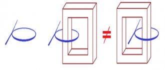
In an ideal transformer, the entire electromagnetic field created by the windings is confined to the magnetic core. In real designs, there is a stray field, the magnitude of which depends on the method of making the coil and the design features of the core. The greater the thickness of the winding, the larger part of the electromagnetic field is closed outside the magnetic circuit.
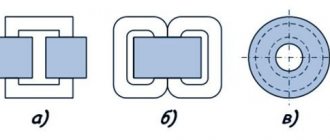
This is also facilitated by the build quality of the magnetic circuit. The gaps between the plates contribute to a sharp increase in dissipation. In this regard, O-shaped cores have the best properties.
Formulas and measurement
The formulas for calculating the inductance of coils are quite complex and have different forms for different types of windings:
- linear conductor;
- single turn coil;
- flat coil;
- solenoid winding;
- toroidal shape.
The greatest difficulties arise when calculating multi-turn multilayer coils, that is, those that make up the windings of transformers.
In the vast majority of cases, an accurate calculation is impossible, so you have to use approximate data and clarify them after measurements.
Formulas for calculating transformer inductance are based on solenoid calculations:
L=µ0µN2S/l, where
µ0 – magnetic constant;
µ – magnetic permeability of the core;
N – number of turns;
S – area of one turn;
l – winding length.
To measure inductance, there are several methods and instruments created on their basis. In most cases, the measurement is made by calculating the inductive reactance of the coil when applying a reference voltage of a given frequency and the measured value of the current through the winding.
In specialized instruments, calculations are performed automatically, and the user only reads the instrument scale, expressed in inductance units - H, mH or μH.
Content
- 1. General part
- 2. Determination of the load on current transformers for measuring instruments
- 3. Determination of the voltage on the secondary winding of the current transformer
- 4. Determination of the load on current transformers for relay protection
- 5. Determination of the calculated multiplicity (Col.) for selecting the permissible load (Zadd.) on current transformers according to the maximum multiplicity curves
- 5.1 Current protection with independent characteristic
- 5.2 Current cut-offs
- 5.3 Overcurrent protection with dependent characteristic
- 5.4 Directional current and distance protection
- 5.5 Differential current protection
- 5.6 Differential-phase high-frequency protection
- 5.7 Longitudinal differential current protection of lines
- 6 Determination of design load Zн
- 7. Determination of the resistance of connecting wires
- 8. Reference data on the consumption of relay equipment
How to measure at home
Instruments for directly measuring inductance are expensive and are rarely used at home. Results can be obtained with acceptable accuracy using conventional instruments for measuring alternating current: an ammeter and a voltmeter. An ohmmeter is also needed.
The procedure is as follows:
- Using an ohmmeter, determine the active resistance of the winding R.
- Connect the transformer in series with the ammeter to the network.
- A voltmeter is connected parallel to the winding.
- According to the instrument readings, the impedance of the transformer is determined: Z=U/I
- Inductive reactance is found by subtracting active resistance from impedance: XL=ZR
- Inductance is determined by the formula: L=XL/(2πf), where π is pi 3.14, f is the measurement frequency.
As a rule, the active resistance of the winding is significantly (several orders of magnitude) less than the inductive one, so it can be ignored. This is why connecting a transformer to a DC voltage circuit causes a short circuit. The winding current will be limited only by the active resistance.
Determination of the load on current transformers for relay protection
The load on the CT for relay protection consists of series-connected resistances of relay equipment, connecting wires and transition resistances in contact connections. The magnitude of the secondary load also depends on the CT connection diagram and on the type of short circuit.
Relay protection under short-circuit conditions usually operates at high currents, which are many times higher than the rated current of the CT. Calculations and operating experience have established that to ensure proper operation of relay protection, CT errors should not exceed the maximum permissible values.
According to the PUE, this error, as a rule, should not be more than 10%.
In GOST 7746-88, the accuracy of CTs used for relay protection is normalized by their total error (ε), caused by the magnetizing current. According to the condition ε < 10%, the curves of the maximum CT multiplicities were constructed.
In this case, the largest ratio of the primary current to its rated value, at which the total error at a given secondary load does not exceed 10%, is called the maximum factor (K10).
According to the same GOST, CT supply plants are required to guarantee the value of the nominal maximum multiplicity (K10n), at which the total error of a CT operating with a rated secondary load does not exceed 10%.
To find the permissible load using the maximum multiplicity curves, it is necessary to first determine the calculated short-circuit current multiplicity, i.e., the ratio of the short-circuit current at the design point to the minimum CT current (Colorful)