In order to choose the type and power of an electric pumping installation, it is necessary to decide on the water supply scheme based on local conditions. Water is supplied mainly through a water boiler or water tank driven by centrifugal pumps from asynchronous motors. Direct supply of water from the pump to the distribution network is carried out in open irrigation systems driven by asynchronous motors.
For the adopted water supply scheme, a pump is selected (in most cases, a reliable and easy-to-use centrifugal pump).
To select a pump and determine its power based on water consumption, the required flow and pressure are determined.
The flow rate Q n (l/h) of the pump is found from the following relationship:
where Qmaxh is the possible maximum hourly water flow, l/h, k h is the coefficient of unevenness of hourly flow, k day is the coefficient of unevenness of daily flow (1.1 - 1.3), η is the efficiency of the installation, taking into account water losses), Q avg .day - average daily water consumption, l/day.
The pump pressure is selected so that it can supply water at the required pressure to a given point. The required pump head Nntr is determined by the suction height Hvs and the discharge height Nng, the sum of which determines the static head Hc, losses in the pipelines H p and the pressure difference at the upper RVu and lower Rnu levels.
Considering that the pressure H = P/ ρg, where P is pressure, Pa, ρ is the density of the liquid, kg/m3, g - 9.8 m/s2 is the acceleration of gravity, g is the specific gravity of the liquid, k/m3, we obtain :
Нntr = Hc + H p + (1/ ρ ) x (Pvu - Rnu)
Knowing the required flow and pressure, a pump with suitable parameters is selected from the catalog, taking into account the possible rotation speed of the drive motor. Next, determine the power of the pump motor.
Based on the universal characteristics of the selected pump, its supply Qn, pressure Nn is specified and the efficiency factor ηn and pump power Pn are determined.
Power (kW) of the pump drive motor P dv = (k w x ρ x Qn x Nn) / (ηn x ηp),
where - k is the safety factor, depending on the power of the pump electric motor: P, kW - (1.05 - 1.7), because in real operating conditions of pumps, water leaks from the pressure pipeline may occur (due to loose connections, pipeline breaks, etc.), so electric motors for pumps are selected with a certain power reserve. The greater the power, the lower the safety factor can be accepted. So for a pump electric motor power of 2 kW - k z = 1.5, 3 kW - k z = 1.33, 5 kW - k z = 1.2, with a power greater than 10 kW - k z = 1.05 - 1.1. ηп - transmission efficiency ( for direct transmission 1, V-belt 0.98, gear 0.97, flat belt 0.95), ηn - efficiency of piston pumps 0.7 - 0.9, centrifugal 0.4 - 0.8, vortex 0.25 - 0, 5.
For centrifugal pumps, the correct choice of angular speed of the pump is especially important, since its performance is proportional to the angular speed, pressure and torque are proportional to the square of the angular speed, power is its cube: Q ≡ ω, H ≡ ω 2, M ≡ ω 2, P ≡ ω 3
From these relationships it follows that as the angular speed of the pump increases, its power increases, which can lead to overheating of the electric motor. If the angular speed of the engine is underestimated, the pump pressure may be insufficient for the design flow.
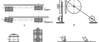
When choosing an electric pump unit from the catalog, it is necessary to take into account its operating characteristics (Fig. 1) and the characteristics of the line on which the pump operates, that is, the relationship between the flow and the total value of the pressure required to raise water to a given height, overcome hydraulic resistance and create excess pressure at the outlet of the discharge pipeline. It is necessary to strive to ensure that operating point A is in the zone of maximum unit efficiency values.
Rice. 1. Characteristics of the pump at various speeds (1, 2, 3, 4), lines at various degrees of throttling (5, 6) and efficiency (7) of the pump at the rated speed.
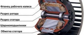
The type of electric motor is selected based on environmental conditions and installation features. For example, to drive submersible pumps of the ECV type, electric motors with a power of 0.7 - 65 kW of a special design of the PEDV type are used, designed for operation in boreholes with a diameter of 100 to 250 mm with a supply to a height of up to 350 m. The stator winding of the motor is made of wire with polyvinyl chloride moisture resistant isolation.
The electric motor together with the pump is installed in the well immersed in the pumped water (Fig. 3). An example of a unit symbol: ETsV-6-10-80-M, where ETsV-6 is an electric pump well unit for water with characteristic “6” for the diameter of the well, namely for a well with an internal diameter of 149.5 mm, 10 is the nominal pump flow, m3/h, 80 - nominal pressure, m, M - type of climatic version according to GOST 15150-69.
Symbol of the electric motor used in the unit: PEDV4-144 (PEDV - water-filled submersible electric motor, 4 - rated power, kW, 144 - maximum cross-sectional size, mm).
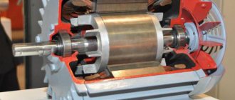
Rice. 2. Electric pump centrifugal well unit for water: 1 - pump, 2 - holder, 3 - head, 4 - check valve, 5 - impeller, 6 - blade outlet, 7 - coupling, 8 - motor, 9 - upper bearing shield, 10 — stator, 11 — rotor, 12 — lower bearing shield, 13 — bottom, 14 — plug, 15 — filter plug, 16 — pin, 17 — mesh, 18 — casing
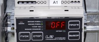
Rice. 3. Layout of the unit in the well: 1 - unit, 2 - water-lifting column, 3 - dry-running sensor, 4 - cable, 5 - coupling, 6 - support plate or head, 7 - elbow, 8 - three-way valve, 9 - pressure gauge, 10 - valve, 11 - control and protection station, 12 - clamp, 13 - filter
The drive of non-submersible centrifugal and vortex pumps uses asynchronous squirrel-cage motors and phase-wound rotor motors with moisture-resistant insulation with a power of 1.5 - 55 kW.
Submersible electric pumps, depending on the level of the aquifer, are operated at depths of 40 - 230 m.
The mechanical characteristics of a centrifugal pump have a fan type. The frictional resistance moment in the pump bearings is Ms - 0.05 Mn.
The average torque of a piston pump when operating on a main line, where a constant pressure is maintained, does not depend on the angular speed of rotation. The piston pump is started with the valve on the pressure pipeline open. Otherwise an accident may occur.
Electric motor power calculation
The conversion of electrical energy into kinetic energy is carried out using various types of electric motors. These devices are widely used in modern production and in everyday life. Most often, electric motors serve as electric drives for machines and mechanisms and are used to ensure the operation of pumping equipment, ventilation systems and many other units and devices. In connection with such a wide application, the calculation of electric motor power is of particular relevance. For these purposes, many different methods have been developed that allow calculations to be performed in relation to specific operating conditions.
Designations of climatic version
| IN | Universal models for use on land and at sea |
| M | Drives for use in cold or temperate marine climates |
| ABOUT | Operation on land |
| T | Engines for use in tropical climates |
| TV | Tropical humid climate |
| TS | Operation in dry tropics |
| U | The most popular type of electric motors is for use in temperate climates |
| X | Electric motor for operation in cold regions |
| HL | Electric motors adapted to cold climates |
Accommodation
| 1 | In open area |
| 2 | In rooms with free access of air |
| 3 | Indoor premises |
| 4 | Electric motor for installation in workshops where the temperature and humidity conditions can be regulated (there is a ventilation system, heat supply) |
| 5 | High humidity areas with a high probability of condensation |
Main types of electric motors
There are many types and modifications of electric motors. Each of them has its own power and other parameters.
The main classification divides these devices into DC and AC motors. The first option is used much less frequently, since its operation requires the presence of a direct current source or a device that converts alternating voltage into direct current. Fulfilling this condition in modern production will require significant additional costs.
But, despite significant disadvantages, DC motors have a high starting torque and operate stably even at high overloads. Due to their qualities, these units are widely used in electric transport, in the metallurgical and machine tool industries.
However, most modern equipment runs on AC motors. The operation of these devices is based on electromagnetic induction, which is created in a magnetic field by a conducting medium. The magnetic field is created using windings flowing around currents or using permanent magnets. Electric motors operating on alternating current can be synchronous or asynchronous.
The use of synchronous electric motors is practiced in equipment where a constant rotation speed is required. These are DC generators, pumps, compressors and other similar installations. Different models differ in their own technical characteristics. For example, the rotation speed can be in the range of 125-1000 rpm, and the power reaches 10 thousand kilowatts.
Many designs have a short-circuited winding located on the rotor. With its help, if necessary, an asynchronous start is made, after which the synchronous motor continues to operate as usual, minimizing electrical energy losses. These engines are characterized by their small size and high efficiency.
Asynchronous AC motors have become much more widespread in the manufacturing sector. They are characterized by a very high frequency of rotation of the magnetic field, significantly exceeding the speed of rotation of the rotor. A significant disadvantage of these devices is considered to be a decrease in efficiency to 30-50% of the norm at low loads. In addition, during start-up, the current parameters become several times greater compared to operating indicators. These problems are eliminated by using frequency converters and soft starters.
Asynchronous motors are used in those facilities where frequent switching on and off of equipment is required, for example, in elevators, winches, and other devices.
Gear pump brands
Let's look at the list of the most common brands of gear pumps:
External (external) gear pumps.
- NS
- G11
- NMS
- G.P.
- HY/ZFS - Bosch
- 1PF2G2 - Rexroth
- IPH - Duplomatic
- X1P - Vivolo
- GHP - Marzocchi
Brands and manufacturers of internal gear pumps
- PGF3 Rexroth
- PGH4 Rexroth
- IGP5 Duplomatic
- IGP5 Duplomatic
Formulas for calculating the flow of a gear pump
The calculation diagram for determining the supply of a gear pump, and the main dependencies are shown in the figure:
Another form of writing the formula is also common. The theoretical flow of a gear pump can be determined using the relationship:
- where D is the diameter of the protrusion circle in mm,
- d is the diameter of the initial circle in mm,
- b - gear width in mm,
- n is the number of gear revolutions per minute.
Source
Calculation of electric motor power for a pump
The choice of electric motor for a pumping installation depends on specific conditions, first of all, on the water supply scheme. In most cases, water is supplied using a water tank or a water boiler. Centrifugal pumps with asynchronous motors are used to drive the entire system.
The selection of the optimal pump power is carried out depending on the need for fluid supply and pressure. The QH pump flow is measured in liters delivered per hour and is designated as l/h. This parameter is determined by the following formula: Qn = Qmaxch = (kch x kday x Qav.day) / (24 η), where Qmaxch is the possible maximum hourly water flow rate, l/h, kch is the coefficient of unevenness of hourly flow, kday is the coefficient of unevenness daily flow rate (1.1 - 1.3), η - efficiency of the pumping unit, taking into account water losses), Qavg.day - value of the average daily water flow rate (l/day).
The optimal water pressure should ensure its supply to the specified location, subject to the required pressure. The required parameters of the pump pressure (Hntr) depend on the suction height (Hvs) and the discharge height (Nng), which together determine the indicators of static pressure (Hs), losses in pipelines (Hp) and the pressure difference between the upper (Pvu) and lower (Pnu) levels.
Based on the fact that the pressure value will be equal to H = P/ρg, where P is pressure (Pa), ρ is the density of the liquid (kg/m3), g = 9.8 m/s2 is the acceleration of free fall, g is the specific liquid weight (kg/m3), the following formula is obtained: Hntr = Hc + Hp + (1/ρ) x (Pvu – Rnu).
After calculating the water flow and pressure from the catalog, you can already select a pump with the most suitable parameters. In order not to be mistaken with the power of the electric motor, it must be determined by the formula: Pmod = (kз x ρ x Qн x Нн) / (ηн x ηп), where kз is a safety factor depending on the power of the pump motor and is 1.05 – 1, 7. This indicator takes into account possible water leaks from the pipeline due to loose connections, pipeline breaks and other factors, so electric motors for pumps must have some power reserve. The higher the power, the lower the safety factor can be assumed.
Briefly about the main thing
The useful power of a pump is characterized by the amount of water pumped over a certain period of time. The amount of energy spent on this work is defined as power consumption. The ratio of these values shows the efficiency of the pump. When choosing a pump, the design and technical features, type of liquid, and performance characteristics are taken into account.
The operation of a pump is characterized by 3 main parameters - performance, pump and power. When calculating power, the following number of factors are taken into account:
- Source depth.
- Static and dynamic level.
- Volume consumed.
- Diameter of pipes or rings.
- Composition of water.
- Height from source to receiver.
- Pressure in the water supply.
To calculate power, a special formula is used - P = Main * P * Uvzh / 3960, the values for which are measured in a special way. In private practice, the most commonly used types of pumps are surface pumps, submersible pumps, centrifugal pumps and circulation pumps. Calculation of pressure and productivity for each of them has its own specifics.
Calculation of engine power formula for compressor
When choosing an electric motor that is most suitable for the operation of a particular compressor, it is necessary to take into account the long-term operation of this mechanism and the constant load. The required power of the RDV engine is calculated in accordance with the power on the shaft of the main mechanism. In this case, the losses arising in the intermediate link of the mechanical transmission should be taken into account.
Additional factors are the capacity, purpose and nature of the production where the compressor equipment will be operated. They have an impact and the equipment may require minor but ongoing adjustments to maintain proper performance.
The engine power can be determined using the formula: , in which:
- Q – compressor performance or flow value (m 3 /s);
- A – work to perform compression (J/m 3 );
- ηк – indicator efficiency (0.6-0.8) to take into account power losses during real air compression;
- ηп – mechanical efficiency (0.9-0.95) taking into account the transmission between the engine and the compressor;
- kz – safety factor (1.05-1.15) to take into account factors that cannot be calculated.
Work A is calculated using a separate formula: A = (Au + Aa)/2, where Au and Aa represent isothermal and adiabatic compression, respectively.
The value of the work that must be done before the required pressure appears can be determined using the table:
Operating modes
The drive operating mode sets the load level on the electric motor. It can be constant (or almost constant) and changing. In any case, its nature must be taken into account in calculations when choosing an electric motor . The basis for analysis is the modes provided for by current standards. For an electric motor, there are 9 of them; they are designated by the letter S and a number.
- S1 - continuous load, constant throughout the entire period until the internal temperature in the case reaches the limit values.
- S2 – short-term operating mode (the temperature during the entire operating time of the drive does not reach the set level). During idle periods, the engine is cooled to ambient temperature. When choosing an electric motor for short-term loads, it is important to consider the overload capacity of the electric drive.
- S3 - periodic short-term load. In this case, the mechanism is turned on and off according to a certain schedule. During operation, the elements of the device do not have time to heat up to the values set in the passport, and during stoppages they are completely cooled. When choosing, it is important to take into account the specific schedule - the duration of stops, losses on transitions and the permissible number of drive starts per set unit of time.
- S4 - short-term schedule with frequent starts.
- S5 - periodic short-term with electric braking. As in the case of S4 mode, the features of choosing an electric motor for such operating conditions are the same as for S
- S6 (continuous periodic short-term). Starts alternate with idling.
- S7 (according to schedule with continuous short-term operation and electric braking).
- S8 (periodic with continuous operation in short periods of time, provides for changes in load and rotation speed simultaneously).
- S9 - non-periodic operation, changing simultaneously with the shaft speed. Most modern engines designed for long-term operation are adapted to it.
Electric motor power calculation
Electric motor power by current can be calculated using our online calculator:
The result can be rounded to the nearest standard power value.
Standard values of electric motor power : 0.25; 0.37; 0.55; 0.75; 1.1; 1.5; 2.2; 3.0; 4.0; 5.5; 7.5; eleven; 15; 18.5; 22; thirty; 37; 45; 55; 75 kW, etc.
Engine power is calculated using the following formula:
P=√3UIcosφη
- U - Rated voltage (voltage to which the electric motor is connected);
- I - Rated current of the electric motor (taken from the passport data of the electric motor , and in their absence is determined by calculation);
- cosφ - Power factor - the ratio of active power to total power (taken from 0.75 to 0.9 depending on the power of the electric motor);
- η - Efficiency factor - the ratio of the electrical power consumed by the electric motor from the network to the mechanical power on the motor shaft (taken from 0.7 to 0.85 depending on the power of the electric motor);
Motor current calculation
The rated and starting current of an electric motor can be calculated by power using our online calculator:
The rated motor current is calculated using the following formula:
Inom=P/√3Ucosφη
- P - Rated power of the electric motor (taken from the motor’s passport data or determined by calculation);
- U - Rated voltage (voltage to which the electric motor is connected);
- cosφ - Power factor - the ratio of active power to total power (taken from 0.75 to 0.9 depending on the power of the electric motor);
- η - Efficiency factor - the ratio of the electrical power consumed by the electric motor from the network to the mechanical power on the motor shaft (taken from 0.7 to 0.85 depending on the power of the electric motor);
The starting current of the electric motor is calculated using the formula:
Istart=Inom* K
- K - Starting current multiplicity, this value is taken from the electric motor passport, or from catalog data (in the above online calculators, the starting current multiplicity is determined approximately based on the other specified characteristics of the electric motor).
Energy efficiency
Energy efficiency is an indicator of the rational operation of equipment, when its consumption remains as low as possible at a sufficient load level. This is one of the key conditions for the return on investment in production equipment. The energy efficiency of an engine can be assessed by its efficiency, which is determined by the formula:
η=P2 / P1
Explication:
- P2 is the useful power of the electric motor on the shaft;
- P1 - consumption (active power consumed to operate the drive from the network).
The modern market for electric motors is standardized according to energy efficiency classes. They are defined by the international standard IEC 60034-30. There are 3 such classes in total (IE 1-3). The higher the energy efficiency class, the more the user of the device saves. For example, choosing a 55 kW mechanism with an increased energy efficiency class will save the enterprise up to 8000 kW of resource per year.
Calculation of electric motor power factor
Online calculation of power factor (cosφ) of an electric motor
Calculation of cosφ (cosine phi) of the engine is carried out using the following formula:
cosφ=P/√3UIη
- P - Rated power of the electric motor (taken from the motor’s passport data or determined by calculation);
- U - Rated voltage (voltage to which the electric motor is connected);
- I - Rated current of the electric motor (taken from the passport data of the electric motor , and in their absence is determined by calculation);
- η - Efficiency factor - the ratio of the electrical power consumed by the electric motor from the network to the mechanical power on the motor shaft (taken from 0.7 to 0.85 depending on the power of the electric motor);
Calculation of electric motor efficiency
Online calculation of efficiency (efficiency) of an electric motor
The efficiency of the electric motor is calculated using the following formula:
η=P/√3UIcosφ
- P - Rated power of the electric motor (taken from the motor’s passport data or determined by calculation);
- U - Rated voltage (voltage to which the electric motor is connected);
- I - Rated current of the electric motor (taken from the passport data of the electric motor , and in their absence is determined by calculation);
- cosφ - Power factor - the ratio of active power to total power (taken from 0.75 to 0.9 depending on the power of the electric motor);
Did you find these online calculators useful? Or maybe you still have questions ? Write to us in the comments!
Didn’t find an article on the website on a topic that interests you regarding electrical engineering? Write to us here. We will definitely answer you.
Production and professional assistance in choosing an electric motor
PTC Privod LLC carries out a full cycle of production and sales of electric motors of various technical characteristics and designs. We, like no one else, know how important a quality choice of electric motor, compressor gearbox, fan, pump and other types of equipment is. Therefore, we are always ready to help the customer with calculations and suggest which model should be chosen. Ask our engineers any questions - they will be happy to guide you on prices, delivery times, performance calculations and any other issues.
Applications for the production and delivery of our products can be left directly on the website (feedback form) or sent by email. Consultations are provided online and by telephone. Contact us, we will help you select high-quality equipment for use in the specific conditions of the work site. PTC Privod LLC delivers its products throughout Russia and the CIS countries.
DC motors
Based on Newton's principle of mechanics, which states that all motion is relative, a DC electric motor can be called a synchronous machine. Although the magnetic fields of the stator and rotor are stationary in it, the rotation of the shaft occurs due to the effect of repulsion of like poles of magnets and attraction of unlike poles.
Their position relative to each other is synchronized by a special device - a collector located on the rotor shaft. This is a copper ring divided into sectors by a dielectric. The ends of the rotor windings are connected to these sectors and create contact pairs.
They are supplied with direct current through carbon brushes. As the shaft rotates, poles switch between pairs. The stator magnetic field can be created by metals with residual magnetism or by the passage of current through the windings. The latter are used in high-power electric machines.
Their advantage is a high efficiency, up to 98%, as well as consistently high torque and low dependence on overloads. DC motors are excellent for driving lifting mechanisms, as well as for traction in electric vehicles.
They are very easy to control: to reduce the rotation speed, you just need to reduce the amount of applied voltage, and to reverse it, just change the polarity. The disadvantage is the complexity of the device and the low reliability of the brush assembly, its tendency to spark and be noisy. In addition, DC voltage is difficult to transmit over long distances, which is why there are no main lines of this type. You will have to create the power yourself, using rectifier or inverter circuits. You can also read about DC motors here.
Brushed motors
They are similar in design to DC motors. However, they are powered by single-phase alternating current. Their stator field winding is connected in series with the armature winding. The rotation of the shaft occurs due to the synchronous change of poles of the magnetic field in the stator and rotor windings.
The advantages listed above - high torque, insensitivity to overloads - also include the fact that this is the only AC electric machine that can be controlled without problems.
To change the shaft rotation speed, it is enough to reduce the supply voltage, and to reverse it, swap the connection points of the collector unit with the stator winding. Therefore, commutator motors are widely used in household electrical appliances.
For example, in washing machines, drills and other electrified tools. The disadvantages, the main of which is the complexity and low reliability of the brush assembly, include the inability to connect three-phase voltage. Simply because in this case there should be six brushes. This limits the maximum power of the motors: for single-phase machines at a voltage of 220 volts, this value does not exceed 2.5 kilowatts.
AC synchronous motors
Their stator winding is powered by three-phase alternating current, and the rotor winding is powered by direct current. In order for their magnetic poles to mesh and cause the shaft to move, such an electric motor must be spun manually or by another motor. In fact, they are an alternator operating in rotation mode. The advantage of the machine is high torque and stable rotation speed.
Characteristic features of gear pumps
In all gear pumps:
- there are three main elements - a stationary stator and a rotating rotor and contactors
- the suction and discharge chambers are hermetically separated due to the simultaneous closure of the stator, rotor and contactors
- supply is carried out by creating a volume in the suction chamber, hermetically cut off by the contactor
- a pinched volume is formed
- the distribution of liquid in the suction and discharge cavities is slotted, which means there is no need for spools and valves
- contactors have one degree of freedom
- the fluid supply is uneven, there is a pulsation of supply
- pump flow does not depend on load
Many of these features are also typical for other positive displacement hydraulic machines, which is not surprising because gear pumps are positive displacement.
Asynchronous electrical machines
In them, the magnetic field of the rotor is a product of the rotating magnetic field of the stator. Since there is an air gap between these machine parts, energy transfer between them occurs with losses. Therefore, the phase of the current in the rotor lags behind the phase of the current in the stator by a small angle (no more than 100), which determines the value of the power factor cosφ. This lag is the reason why an electric machine of this type is called asynchronous.
Squirrel-cage motors
Their rotor winding is a set of metal rods that connect two rings. The resulting figure is called a “squirrel wheel”. At the moment voltage is applied to the stator winding, a short circuit current arises in the rotor, the energy of which is spent on unwinding the shaft and is thereby extinguished. It has a slightly lower efficiency than synchronous machines, it does not exceed 80%.
After gaining speed, it has a very stable torque on the shaft and can withstand overloads well. The main advantages of such engines are their simplicity and reliability, thanks to which they are very widespread. Disadvantages: complexity of management.
To change the rotation speed, it is necessary to change the frequency of the supply voltage or the number of stator windings, which determines the number of poles of the electromagnet - the more there are, the lower it is. Also, electric motors with a squirrel-cage rotor are characterized by a large starting current that overloads the network, as well as a sharp increase in torque when power is connected, which can cause damage to the drive gearbox.
Wound rotor motors
The start-up of high-power squirrel-cage asynchronous motors (more than 30 kW) is associated with extreme overload of the supply network. To eliminate this phenomenon, machines with a wound rotor are used, the winding of which consists of three coils connected by a star. Their ends are connected by carbon brushes to three slip rings located on the motor axis.
Unlike a DC motor commutator, they are not divided into sectors. When starting such a machine, a three-phase rheostat is used, the resistance of which is maximum at the moment of start-up. By gradually reducing the active resistance of the rotor, a smooth rotation of the electric motor shaft is achieved. When the nominal speed is reached, it is short-circuited.
By changing the rotor resistance, you can change the rotation speed. The advantage of a machine of this type is the absence of overload at the time of start-up and a smooth increase in torque. Therefore, it is used in lifting equipment. The disadvantage is the complexity of the device and lower efficiency than that of machines with a squirrel-cage rotor, it is no more than 60%.