The article describes how a thyristor power regulator works, the diagram of which will be presented below
In everyday life, very often there is a need to regulate the power of household appliances, such as electric stoves, soldering irons, boilers and heating elements, in transport - engine speed, etc. The simplest amateur radio design comes to the rescue - a power regulator on a thyristor. Assembling such a device will not be difficult; it can become the very first home-made device that will perform the function of adjusting the temperature of the soldering iron tip of a novice radio amateur. It is worth noting that ready-made soldering stations with temperature control and other nice functions are an order of magnitude more expensive than a simple soldering iron. A minimal set of parts allows you to assemble a simple thyristor power regulator for wall mounting.
For your information, surface mounting is a method of assembling radio-electronic components without using a printed circuit board, and with good skill it allows you to quickly assemble electronic devices of medium complexity.
You can also order an electronic thyristor regulator constructor, and for those who want to figure it out on their own, a diagram will be presented below and the principle of operation will be explained.
How does a thyristor work?
A thyristor is a controlled semiconductor device capable of conducting current in one direction. The word “controlled” was used for a reason, because with its help, unlike a diode, which also conducts current only to one pole, you can select the moment when the thyristor begins to conduct current. The thyristor has three outputs:
- Anode.
- Cathode.
- Control electrode.
In order for current to begin flowing through the thyristor, the following conditions must be met: the part must be in a circuit that is energized, and a short-term pulse must be applied to the control electrode. Unlike a transistor, controlling a thyristor does not require holding the control signal. The nuances do not end there: the thyristor can be closed only by interrupting the current in the circuit, or by generating an anode-cathode reverse voltage. This means that the use of a thyristor in DC circuits is very specific and often unwise, but in AC circuits, for example in a device such as a thyristor power regulator, the circuit is constructed in such a way that a condition for closing is ensured. Each half-wave will close the corresponding thyristor.
Most likely, you don’t understand everything? Do not despair - below we will describe in detail the process of operation of the finished device.
Methods for regulating phase voltage in the network
- There are several ways to regulate alternating voltage in thyristors: you can skip or disable the output on the regulator as many as four half-cycles (or periods) of alternating voltage. It can be turned on not at the beginning of the half-cycle of the mains voltage, but with a certain delay. During this time, the voltage at the output of the regulator will be equal to zero, and the total power will not be transferred to the output of the device. During the second part of the half-cycle, the thyristor will begin to conduct current and a special input voltage will appear at the output of the regulator.
- The delay time in most cases is called the opening angle of the thyristor, since during the zero angle value almost all the voltage from the input will go to the output, only the drop in the open area of the thyristor will begin to be lost. As the total thyristor angle increases, the voltage regulator will significantly reduce the output voltage parameter.
- The regulating characteristic of such a device during its operation, during active load, is carried out especially intensively. At an angle of 90 degrees (electrical), the output from the connector will be half the input voltage, and at a total angle of 180 electrical degrees, the output will be zero.
Based on the principles and features of phase voltage regulation, it is possible to construct certain regulation, stabilization, and, in some cases, soft start schemes. To achieve a smoother start, the voltage should be increased over time from zero to the maximum value. Thus, during the opening of the thyristor, the maximum value should change to zero.
Is it possible to regulate engine speed?
I think many of the readers have seen or used drills, angle grinders, which are popularly called “grinders,” and other power tools. You may have noticed that the number of revolutions depends on the depth of pressing the trigger button of the device. It is in this element that a thyristor power regulator is built in (the diagram of which is shown below), with the help of which the number of revolutions is changed.
Note! The thyristor regulator cannot change the speed of asynchronous motors. Thus, the voltage is regulated on commutator motors equipped with a brush assembly.
Simple voltage regulator
To produce a simple 12-volt system, you will need key elements such as a rectifier, a generator and a battery. The generator is one of the main components. For manufacturing, you will need the above-mentioned radio components, as well as a circuit of a simple power regulator. It is worth noting that it does not contain stabilizers.
For manufacturing it is necessary to prepare the following elements:
- 2 resistors;
- 1 transistor;
- 2 capacitors;
- 4 diodes.
It is better to install a cooling system specifically for the transistor. This will avoid system overloads. It is better to install the device with a good power reserve in order to subsequently charge batteries with a small capacity.
Scheme of a thyristor power regulator with one and two thyristors
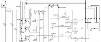
A typical circuit for assembling a thyristor power regulator with your own hands is shown in the figure below.
The output voltage of this circuit is from 15 to 215 volts; in the case of using the indicated thyristors installed on heat sinks, the power is about 1 kW. By the way, the switch with the light brightness control is made according to a similar scheme.
If you don't need to fully regulate the voltage and just need to get an output of 110 to 220 volts, use this diagram, which shows a half-wave power regulator on a thyristor.
Methods for closing a thyristor
There are many ways to close thyristors. But first of all, it is necessary to remember that applying any signals to the electrode will not be able to close it and extinguish the action. The electrode is only capable of starting the device. There are also analogues - lockable thyristors. But their intended purpose is a little broader than that of conventional switches. The classic thyristor voltage regulator circuit can only be turned off by interrupting the current supply at the anode-cathode level.
There are at least 3 ways to close the power regulator on the Ku202n thyristor. You can simply disconnect the entire circuit from the battery. This will turn off the diode. But if you turn on the device again, it will not turn on, since the thyristor remains in the closed state. It will remain in this position until the corresponding button is pressed.
The second way to close a thyristor is to interrupt the current supply. This can be done by simply shorting the cathode connection of the anode using ordinary wire. You can check it on a circuit with a simple LED instead of a device. If a wire jumper is connected as indicated above, then all the voltage will go through the wire, and the current level that will go to the thyristor will be zero. After taking the wire back, the thyristor will close and the device will turn off. In this case, the device is an LED, and it will go out. If you experiment with such circuits, you can use tweezers as a jumper.
If instead of an LED you install a high-power heating coil, you can get a complete thyristor regulator.
The third method is to reduce the supply voltage to the minimum, and then reverse the polarity. This situation will result in the device turning off.
How it works?
The information described below is valid for most schemes. Letter designations will be taken in accordance with the first circuit of the thyristor regulator
A thyristor power regulator, the operating principle of which is based on phase control of the voltage value, also changes the power. This principle lies in the fact that under normal conditions the load is affected by the alternating voltage of the household network, changing according to a sinusoidal law. Above, when describing the operating principle of a thyristor, it was said that each thyristor operates in one direction, that is, it controls its own half-wave from a sine wave. What does it mean?
If you periodically connect a load using a thyristor at a strictly defined moment, the value of the effective voltage will be lower, since part of the voltage (the effective value that “falls” on the load) will be less than the mains voltage. This phenomenon is illustrated in the graph.
The shaded area is the area of stress that is under load. The letter “a” on the horizontal axis indicates the opening moment of the thyristor. When the positive half-wave ends and the period with the negative half-wave begins, one of the thyristors closes, and at the same moment the second thyristor opens.
Methods for regulating phase voltage in the network
- There are several ways to regulate alternating voltage in thyristors: you can skip or disable the output on the regulator as many as four half-cycles (or periods) of alternating voltage. It can be turned on not at the beginning of the half-cycle of the mains voltage, but with a certain delay. During this time, the voltage at the output of the regulator will be equal to zero, and the total power will not be transferred to the output of the device. During the second part of the half-cycle, the thyristor will begin to conduct current and a special input voltage will appear at the output of the regulator.
- The delay time in most cases is called the opening angle of the thyristor, since during the zero angle value almost all the voltage from the input will go to the output, only the drop in the open area of the thyristor will begin to be lost. As the total thyristor angle increases, the voltage regulator will significantly reduce the output voltage parameter.
- The regulating characteristic of such a device during its operation, during active load, is carried out especially intensively. At an angle of 90 degrees (electrical), the output from the connector will be half the input voltage, and at a total angle of 180 electrical degrees, the output will be zero.
Based on the principles and features of phase voltage regulation, it is possible to construct certain regulation, stabilization, and, in some cases, soft start schemes. To achieve a smoother start, the voltage should be increased over time from zero to the maximum value. Thus, during the opening of the thyristor, the maximum value should change to zero.
Let's figure out how our specific thyristor power regulator works
Scheme one
Let us stipulate in advance that instead of the words “positive” and “negative”, “first” and “second” (half-wave) will be used.
So, when the first half-wave begins to act on our circuit, capacitors C1 and C2 begin to charge. Their charging speed is limited by potentiometer R5. this element is variable, and with its help the output voltage is set. When the voltage necessary to open dinistor VS3 appears on capacitor C1, the dinistor opens and current flows through it, with the help of which thyristor VS1 will be opened. The moment of breakdown of the dinistor is point “a” on the graph presented in the previous section of the article. When the voltage value passes through zero and the circuit is under the second half-wave, the thyristor VS1 closes, and the process is repeated again, only for the second dinistor, thyristor and capacitor. Resistors R3 and R3 serve to limit the control current, and R1 and R2 serve to thermally stabilize the circuit.
The principle of operation of the second circuit is similar, but it controls only one of the half-waves of alternating voltage. Now, knowing the principle of operation and the circuit, you can assemble or repair a thyristor power regulator with your own hands.
Schematic diagram
When powering powerful loads with direct current, a rectifier circuit (Fig. 1) with four power valves is often used. The alternating voltage is supplied to one diagonal of the “bridge”, the output constant (pulsating) voltage is removed from the other diagonal. One pair of diodes (VD1-VD4 or VD2-VD3) operates in each half-cycle.
This property of the rectifier “bridge” is significant: the total value of the rectified current can reach twice the maximum current value for each diode. The diode voltage limit should not be lower than the amplitude input voltage.
Since the voltage class of power valves reaches fourteen (1400 V), there are no problems with this for a household electrical network. The existing reverse voltage reserve allows the use of valves with some overheating, with small radiators (do not abuse them!).
Rice. 1. Rectifier circuit with four power valves.
Attention! Power diodes marked “B” conduct current “similarly” to D226 diodes (from the flexible lead to the body), diodes marked “VL” - from the body to the flexible lead.
The use of valves of different conductivity allows installation on just two double radiators. If you connect the “housings” of the “VL” valves (minus output) to the device body, then you will only have to isolate one radiator, on which diodes marked “B” are installed. This circuit is easy to install and set up, but difficulties arise if you have to regulate the load current.
If everything is clear with the welding process (attach the “ballast”), then huge problems arise with the starting device. After starting the engine, the huge current is unnecessary and harmful, so it is necessary to quickly turn it off, since every delay shortens the battery life (batteries often explode!).
The circuit shown in Fig. 2 is very convenient for practical implementation, in which the current control functions are performed by thyristors VS1, VS2, and power valves VD1, VD2 are included in the same rectifier bridge. Installation is made easier by the fact that each diode-thyristor pair is mounted on its own radiator. Radiators can be used standard (industrial production).
Another way is to independently manufacture radiators from copper and aluminum with a thickness of over 10 mm. To select the size of the radiators, you need to assemble a mock-up of the device and “drive” it in heavy duty. It’s not bad if after a 15-minute load the thyristor and diode housings do not “burn” your hand (turn off the voltage at this moment!).
The device body must be designed in such a way as to ensure good circulation of air heated by the device. It wouldn’t hurt to install a fan that “helps” move air from bottom to top. Fans installed in racks with computer boards or in “Soviet” gaming machines are convenient.
Rice. 2. Scheme of a current regulator using thyristors.
It is possible to implement an adjustable rectifier circuit entirely using thyristors (Fig. 3). The lower (according to the diagram) pair of thyristors VS3, VS4 is triggered by pulses from the control unit.
The pulses arrive simultaneously at the control electrodes of both thyristors. This design of the circuit is “dissonant” with the principles of reliability, but time has confirmed the operability of the circuit (“the household electrical network cannot burn” thyristors, since they can withstand a pulse current of 1600 A).
Thyristor VS1 (VS2) is connected as a diode - with a positive voltage at the anode of the thyristor, an unlocking current will be supplied through diode VD1 (or VD2) and resistor R1 (or R2) to the control electrode of the thyristor. Already at a voltage of several volts, the thyristor will open and will conduct current until the end of the half-wave of current.
The second thyristor, the anode of which had a negative voltage, will not start (this is not necessary). A current pulse comes to thyristors VS3 and VS4 from the control circuit. The value of the average current in the load depends on the opening moments of the thyristors - the earlier the opening pulse arrives, the larger part of the period the corresponding thyristor will be open.
Rice. 3. Adjustable rectifier circuits are entirely based on thyristors.
Opening thyristors VS1, VS2 through resistors somewhat “dulls” the circuit: at low input voltages, the open angle of the thyristors turns out to be small - noticeably less current flows into the load than in a circuit with diodes (Fig. 2).
Thus, this circuit is quite suitable for adjusting the welding current via the secondary and rectifying the mains voltage, where the loss of a few volts is insignificant.
The circuit shown in Fig. 4 allows you to effectively use a thyristor bridge to regulate current over a wide range of supply voltages.
The device consists of three blocks:
- power;
- phase-pulse control circuits;
- two-limit voltmeter.
Transformer T1 with a power of 20 W provides power to the control unit for thyristors VS3 and VS4 and the opening of “diodes” VS1 and VS2. Opening thyristors with an external power supply is effective at low (car) voltage in the power circuit, as well as when powering an inductive load.
Rice. 4. Thyristor bridge for current control over a wide range.
Rice. 5. Schematic diagram of the thyristor control unit.
Opening current pulses from the 5-volt windings of the transformer are supplied in antiphase to the control electrodes VS1, VS2. Diodes VD1, VD2 pass only positive half-waves of current to the control electrodes.
If the phasing of the opening pulses is “appropriate”, then the thyristor rectifier bridge will work, otherwise there will be no current in the load.
This shortcoming of the circuit can be easily eliminated: just turn the T1 power plug in the opposite direction (and mark with paint how to connect the plugs and terminals of the devices to the AC network). When using the circuit in a starter-charger, there is a noticeable increase in the supplied current compared to the circuit in Fig. 3.
It is very beneficial to have a low-current circuit (mains transformer T1). Breaking the current by switch S1 completely de-energizes the load. Thus, you can interrupt the starting current with a small limit switch, circuit breaker or low-current relay (by adding an automatic shutdown unit).
This is a very important point, since it is much more difficult to break high-current circuits that require good contact for the current to pass through. It is no coincidence that we remembered the phasing of transformer T1. If the current regulator were “built-in” into the charging and starting device or into the welding machine circuit, then the phasing problem would be solved at the time of setting up the main device.
Our device is specially designed to be wide-profile (just as the use of the starting device is determined by the season of the year, welding work has to be carried out irregularly). You have to control the operating mode of a powerful electric drill and power nichrome heaters.
Figure 5 shows a diagram of the thyristor control unit. The rectifier bridge VD1 supplies the circuit with a pulsating voltage from 0 to 20 V. This voltage is supplied through the diode VD2 to the capacitor C1, which provides a constant supply voltage to the powerful transistor “switch” on VT2, VT3.
The pulsating voltage is supplied through resistor R1 to resistor R2 and zener diode VD6 connected in parallel. The resistor “ties” the potential of point “A” (Fig. 6) to zero, and the zener diode limits the peaks of the pulses at the level of the stabilization threshold. Limited voltage pulses charge capacitor C2 to power the DD1 chip.
These same voltage pulses affect the input of the logic element. At a certain voltage threshold, the logic element switches. Taking into account the inversion of the signal at the output of the logic element (point “B”), the voltage pulses will be short-term - around the moment of zero input voltage.
Rice. 6. Pulse diagram.
The next logic element inverts the voltage “B”, so the voltage pulses “C” have a significantly longer duration. While the voltage pulse “C” is in effect, capacitor C3 is charged through resistors R3 and R4.
The exponentially increasing voltage at point “E”, at the moment of crossing the logical threshold, “switches” the logical element. After inversion by the second logic element, the high input voltage at point "E" corresponds to a high logic voltage at point "F".
Two different values of resistance R4 correspond to two oscillograms at point “E”:
- lower resistance R4 - greater steepness - E1;
- greater resistance R4 - lower steepness - E2.
You should also pay attention to the power supply of the base of transistor VT1 with the “B” signal; when the input voltage decreases to zero, transistor VT1 opens to saturation, the collector junction of the transistor discharges capacitor C3 (preparing for charging in the next half-cycle of voltage). Thus, the logic high level appears at point "F" earlier or later, depending on the resistance of R4:
- lower resistance R4 - impulse appears earlier - F1;
- greater resistance R4 - later an impulse appears - F2.
The amplifier on transistors VT2 and VT3 “repeats” the logical signals - point “G”. The oscillograms at this point repeat F1 and F2, but the voltage reaches 20 V.
Through isolation diodes VD4, VD5 and limiting resistors R9 R10, current pulses act on the control electrodes of thyristors VS3 VS4 (Fig. 4). One of the thyristors opens, and a rectified voltage pulse passes to the output of the block.
The smaller resistance value R4 corresponds to the larger part of the half-cycle of the sinusoid - H1, the larger value - the smaller part of the half-cycle of the sinusoid - H2 (Fig. 4). At the end of the half-cycle, the current stops and all thyristors close.
Rice. 7. Scheme of an automatic two-limit voltmeter.
Thus, different values of resistance R4 correspond to different durations of “segments” of sinusoidal voltage on the load. The output power can be adjusted practically from 0 to 100%. The stability of the device is determined by the use of “logic” - the switching thresholds of the elements are stable.
Using the regulator in everyday life and safety precautions
It must be said that this circuit does not provide galvanic isolation from the network, so there is a danger of electric shock. This means that you should not touch the regulator elements with your hands. An insulated housing must be used. You should design the design of your device so that, if possible, you can hide it in an adjustable device and find free space in the case. If the adjustable device is located permanently, then in general it makes sense to connect it through a switch with a dimmer. This solution will partially protect against electric shock, eliminate the need to find a suitable housing, has an attractive appearance and is manufactured using an industrial method.
Purpose
The power regulator is useful in circuits containing the following electrical devices:
Regulator with motor
- electric motors;
- devices that use compressors in their work;
- household appliances: washing machines, fans, vacuum cleaners;
- electrical tools of various kinds;
- various lighting devices.
A simple example of using a regulator in lighting
. Important! It is not recommended to use a phase regulator in circuits that include refrigerators, computers, televisions and other fine-tuned consumers, changes in the nature of whose operation can lead to damage to the device or other unpredictable consequences.
Details and design
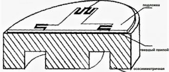
Most of the parts of the device are installed on a semicircular mounting plate, the dimensions and shape of which are adjusted for installation in a metal base case with a diameter of 165 mm of a domestic table lamp model NNB37-60-018 UHL4, manufactured in accordance with GOST 8607-82.
To isolate current-carrying structural elements from the luminaire body, dense fiberglass is used, glued with double-sided mounting adhesive tape and “BF” glue.
Rice. 2. Pinout of transistors KT502, KT503 and thyristor KU221.
The variable resistor is of the SPZ-35 type; it can be replaced, for example, with SPZ-30a, SP-1, SPZ-12, SPZ-4, SPZ-33-32 or similar. An adjustment knob made of insulating material must be placed on the axis of the variable resistor. The remaining resistors are types RPM, MYAT, S1-4, S1-14, S2-14, S2-33 or analogues.
Capacitor C1 is ceramic, type K15-5; instead of such a capacitor, you can install any ceramic or film capacitor with an operating voltage of DC of at least 630 V or AC of at least 275 V, for example, K73-17, K73-24, K73-39. The same capacitors can be replaced with C2 and C4. SZ film capacitor is small-sized.
Instead of GUR460 diodes, you can install FR304 - FR307, FR604G - FR607G, PR3004 -PR3007, SRP300J, 1 N5404 - 1N5408, KD257B - KD257D, KD202M, 2T202T.
Diodes 1N4007 are replaceable with 1N4005, 1N4006, UF4005-UF4007, RU3AM, 1N4936GP, 1N4937GP, FR155 - FR157, KD209B, KD221V, KD243G, KD247D. Instead of the AL316A red LED, any of the AL341, KIPD21, KIPD40, L-1503, RL52, RL54, DB5-436 series will do. An additional hole is drilled in the base of the lamp for the LED.
Instead of the D814D zener diode, any of the D814D1, KS213Zh, 1N4743A, 1N4743A, BZV55C-12, BZV55C-13, TZMC-13 will be suitable. Instead of the KF13001 transistor, MJE13001, MJE13002, MJE13003, MJE340, BF420, BF393, M PSA-42, 2N6517 are suitable.
We will replace the BF421 transistor with BF493, MJE350, 2N6520, 2SA1625, 2SA1700, MPSA-44. Instead of the KT503B transistor, any of the KT503, KT3117, KT6111, KT6113, KT645, SS8050, 2SC2116, 2SD261, SS8050, SS9013 series will do. The KT502E transistor can be replaced by any of the KT502, KT209, KT6112, KT6115, KT639, SS8550, SS9012, 2SA643, 2SA1048, 2SA1150, 2SA1378.
Keep in mind that transistors, even of the same type, but from different manufacturers, may have differences in pinout. SCRs KU221 operate without an additional metal heat sink; SCRs with different letter indices can be installed in pairs. The pinout of the used transistors and SCRs is shown in Fig. 2.
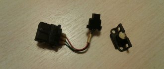
Switch SA1 is installed on the power cord of the lamp. The two-winding inductor L1 is used, ready-made from a computer power supply, made on an W-shaped ferrite core.
Any similar one with a total winding resistance of up to 2 Ohms will do, the more inductance the better. The L2 choke is homemade, wound on two 400NN ferrite rods with a diameter of 8 mm and a length of 40 mm. Each rod has 60 turns of winding wire with a diameter of 0.39 mm wound on it, winding turn to turn over double-sided adhesive paper tape.
Details and design
Most of the parts of the device are installed on a semicircular mounting plate, the dimensions and shape of which are adjusted for installation in a metal base case with a diameter of 165 mm of a domestic table lamp model NNB37-60-018 UHL4, manufactured in accordance with GOST 8607-82.
To isolate current-carrying structural elements from the luminaire body, dense fiberglass is used, glued with double-sided mounting adhesive tape and “BF” glue.
Rice. 2. Pinout of transistors KT502, KT503 and thyristor KU221.
The variable resistor is of the SPZ-35 type; it can be replaced, for example, with SPZ-30a, SP-1, SPZ-12, SPZ-4, SPZ-33-32 or similar. An adjustment knob made of insulating material must be placed on the axis of the variable resistor. The remaining resistors are types RPM, MYAT, S1-4, S1-14, S2-14, S2-33 or analogues.
Capacitor C1 is ceramic, type K15-5; instead of such a capacitor, you can install any ceramic or film capacitor with an operating voltage of DC of at least 630 V or AC of at least 275 V, for example, K73-17, K73-24, K73-39. The same capacitors can be replaced with C2 and C4. SZ film capacitor is small-sized.
Instead of GUR460 diodes, you can install FR304 - FR307, FR604G - FR607G, PR3004 -PR3007, SRP300J, 1 N5404 - 1N5408, KD257B - KD257D, KD202M, 2T202T.
Diodes 1N4007 are replaceable with 1N4005, 1N4006, UF4005-UF4007, RU3AM, 1N4936GP, 1N4937GP, FR155 - FR157, KD209B, KD221V, KD243G, KD247D. Instead of the AL316A red LED, any of the AL341, KIPD21, KIPD40, L-1503, RL52, RL54, DB5-436 series will do. An additional hole is drilled in the base of the lamp for the LED.
Instead of the D814D zener diode, any of the D814D1, KS213Zh, 1N4743A, 1N4743A, BZV55C-12, BZV55C-13, TZMC-13 will be suitable. Instead of the KF13001 transistor, MJE13001, MJE13002, MJE13003, MJE340, BF420, BF393, M PSA-42, 2N6517 are suitable.
We will replace the BF421 transistor with BF493, MJE350, 2N6520, 2SA1625, 2SA1700, MPSA-44. Instead of the KT503B transistor, any of the KT503, KT3117, KT6111, KT6113, KT645, SS8050, 2SC2116, 2SD261, SS8050, SS9013 series will do. The KT502E transistor can be replaced by any of the KT502, KT209, KT6112, KT6115, KT639, SS8550, SS9012, 2SA643, 2SA1048, 2SA1150, 2SA1378.
Keep in mind that transistors, even of the same type, but from different manufacturers, may have differences in pinout. SCRs KU221 operate without an additional metal heat sink; SCRs with different letter indices can be installed in pairs. The pinout of the used transistors and SCRs is shown in Fig. 2.
Switch SA1 is installed on the power cord of the lamp. The two-winding inductor L1 is used, ready-made from a computer power supply, made on an W-shaped ferrite core.
Any similar one with a total winding resistance of up to 2 Ohms will do, the more inductance the better. The L2 choke is homemade, wound on two 400NN ferrite rods with a diameter of 8 mm and a length of 40 mm. Each rod has 60 turns of winding wire with a diameter of 0.39 mm wound on it, winding turn to turn over double-sided adhesive paper tape.
Modern triac regulator circuit
Below is a modern circuit diagram of a triac power regulator. In order to understand the principle of operation of a power regulator on a triac, you need to imagine how it works.
Triacs, unlike thyristors, can operate not only in DC circuits, but also in AC circuits. This is their main difference. The triac also operates in key mode - either open or closed. To open the transition A1-A2, you need to apply a voltage of 2-5 V to the control electrode G relative to pin A1. The triac will open and not close until the voltage between terminals A1-A2 becomes zero.
The triac power regulator circuit operates as follows. AC mains voltage is supplied through the load (incandescent light bulb or soldering iron winding) to terminal A1 of triac VS2 and one of the terminals R2. When the middle terminal of resistor R2 is in the extreme left position, its resistance is 0 and when the voltage in the network begins to increase, capacitor C1 quickly charges. When C1 is charged to a voltage of 30 V, a breakdown of the dinistor VS1 occurs and the current flows to the control electrode G VS2 and the junction of the triac A1-A2 opens (graph 1).
It will be interesting➡ Loop current method for calculating electrical circuits
When you turn the knob of variable resistor R2, its resistance will increase, the charging current of capacitor C1 will decrease and it will take more time for the voltage on it to reach 30 V. Therefore, the triac will open after some time. The greater the value of R2, the longer the charging time of C1 will be and the triac will open with a longer delay. This way, less energy will be supplied to the load.
The given classic circuit of a triac power regulator can also operate at a network voltage of 127, 24 or 12 V. It is only enough to reduce the value of the variable resistor. In the above circuit, the power is regulated not from 0 volts, but from 30, which is more than enough for practical use. This circuit was successfully repeated when repairing the electronic circuit for controlling the rotation speed of a blender motor.
Design and principle of operation of TRM
The thyristor power regulator has its own specifics of operation and control. The power element of the thyristor regulator is opened by exposure to alternating current pulses. It closes only when the supply voltage is zero. Therefore, thyristor power regulators are used when switching exclusively alternating current.
Regulator device:
- power module – thyristors for phase control of load current;
- control circuit power module
- control circuit.
invites you to familiarize yourself with the catalog of thyristor power regulators and buy them at one of the lowest prices in Moscow. We cooperate directly with the manufacturer of the devices presented, so shopping with us is profitable.
The range includes thyristor power regulators for heating elements, IR emitters, incandescent lamps, soldering stations and other devices. To purchase them, simply use the web shopping cart.
You can also compare the selected regulator with other similar devices in the catalog. This will allow you to quickly find exactly what you need.
We provide prompt delivery of all thyristor power regulators presented on the website, as well as other products throughout Russia. You can find more detailed information about this on our website.
Basic functions of the speed controller
The use of such converters allows you to achieve many goals, namely:
- the possibility of stepwise acceleration and reduction of electric motor speed, which leads to reduced loads and less electrical energy consumption;
- you can carry out a smooth start, and with instantaneous maximum acceleration, the motor receives ultra-high loads, overheating the windings and other drives;
- as a means of additional protection of electronic mechanisms;
- reduction in maintenance costs for power units and pumps, as the risks of drive failures, as well as individual mechanisms, are reduced.
Welding machines, voltage stabilizers, PCs, TVs, etc. cannot do without similar built-in devices.