The bipolar power supply is built on adjustable linear stabilizers LM317 and LM337, which are capable of delivering current up to 1.5A, adjusting the output voltage in the range of ±1.25-37V and have protection against short-circuit, overload, and over-temperature. Thus, the adjustable power supply on LM317+LM337 can be used to power various electronic equipment with a stabilized bipolar voltage, with the ability to set the required value.
I made this power supply for the convenience of checking low-power UMZCH.
Main technical characteristics
Input voltage (AC), V ..... no more than 25-0-25
Maximum output current, A….. 2.2
Rated output current, A….. 1.5
Output voltage (DC), V….. adjustable from ±1.25 to ±30
Note. Rated and maximum currents are indicated for a difference of up to 15V between the input and output voltage of the stabilizer. If this difference is greater, then the maximum and rated currents will decrease in accordance with the graph below.
It is also important to know that according to the technical descriptions for LM317 and LM337, in order to obtain the required current, the power dissipation on the stabilizer should not exceed 20 W, otherwise the overload protection will be triggered and the output power will be limited.
LM 317 and LM 337 pin locations
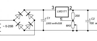
Scheme of a bipolar regulated power supply for LM 317+ LM 337
The AC voltage from the secondary winding of the transformer is supplied to the noise suppression capacitor C1, and then to the diode bridge VDS1, where it is rectified and supplied to the linear stabilizers LM317 and LM337. The LM317 adjustable stabilizer stabilizes the positive arm, and the LM337 adjustable stabilizer stabilizes the negative arm.
Voltage regulation is carried out by trimming resistors R5 and R6. The required value can be calculated using the formula (for a positive leverage):
Description of popular bipolar power supply schemes
The easiest way to organize bipolar power is using a resistive divider. A voltage equal to twice the level of each arm is applied to the input. The common point of connection of the two resistors serves as the common wire.
Organization of bipolar power supply using a resistive divider.
The shoulder voltage is distributed proportionally to the resistance of each resistor. When R1=R2 the output will be symmetrical – U1=U2. The disadvantage of such a divider is that the voltage distribution depends on the load - the consumer shunts the resistors, and if the shunting is different, then the output voltage will also become asymmetrical. To reduce this effect, it is necessary that Rload be much larger than the resistor of the corresponding shoulder. Accordingly, as the consumer’s power increases, the value of each divider resistance will have to be reduced, which will lead to an increase in power consumption through the R1R2 circuit, and soon it will reach unacceptable values.
This drawback is significantly mitigated if capacitors are used instead of resistors. The voltage is distributed proportionally to the capacitances, with C 1=C2 at the output U1=U2.
Capacitive divider.
The capacitance depends on the load, so oxide (formerly called electrolytic) capacitors are used in this circuit. In theory, no current flows through circuit C1C2 and no power is consumed. In practice, oxide capacitors have a noticeable leakage current. It is not so large as to create problems with power consumption, but it is individual for each capacitor, and creates an initial asymmetry of the arms. This effect enhances the large permissible spread of electrolyte capacities. Therefore, it is useful to place a resistor of the same value (several hundred ohms or several kilo-ohms) in parallel with the capacitors. They will have almost no effect on power consumption, and the distribution of levels will be leveled.
A divider made of oxide capacitors with a large capacity can only be used in DC circuits.
Practical circuit of a power supply with a capacitive divider.
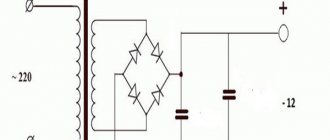
In practice, you can use a similar circuit in conjunction with a step-down transformer and a full-wave bridge rectifier. Capacitors serve as both a smoothing filter and a divider. Equalizing dividers are not necessary if the transformer is tapped from the middle of the secondary winding.
Bipolar power supply with a midpoint transformer.
The independence of the output voltage from the load is brought to a new level by the implementation of the power supply according to a stabilization circuit. In a simple version, it can be performed on two transistors, the bases of which are supplied with half the power from a resistive divider (both resistances must be equal).
Stabilized two-pole power supply.
For the upper (positive) arm, you can use the KT815 (KT817) transistor. For the lower (negative) KT814 (KT816) or other corresponding structure.
Bipolar voltage divider with operational amplifier.
A circuit using an operational amplifier has even better parameters. The negative feedback circuit on resistor R3 provides a good stabilization coefficient. The divider by R1R2 sets the level of the midpoint.
Bipolar power supply with linear stabilizers in each arm.
A simple and stable circuit is obtained using linear stabilizers of the 78XX series (79XX for the negative arm). A transformer with a midpoint is used; the C1C3 circuit serves as a divider. Stabilizer chips are switched on according to the standard circuit, diodes VD1 and VD3 protect the corresponding channel from reverse polarity voltage.
To build a linear stabilizer at the input, you must have a voltage reserve.
Using a similar circuit, you can build a laboratory power supply, but it is more convenient to use a circuit that is controlled by the output level. Such a source can be built on a transformer with a middle tap. If it is not there, you can use two identical secondary windings (rewind or rewind) with a separate rectifier for each channel, or even use two separate transformers. Such a source can be used as two separate unipolar channels , and by connecting the plus of one to the minus of the other with a jumper, you can get an adjustable bipolar power supply.
Bipolar laboratory with separate channels.
The circuit of such a bipolar power supply contains two separate channels, each of which is made on an LM317 chip. The bridge diodes and transistor must be designed for the full current of the channel, the transformer - for the total power of the two paths. The laboratory technician allows you to obtain a voltage from 1.25 to 35 volts in each channel (depending on the input voltage). If it is necessary to obtain bipolar voltage, the negative terminal of one path is connected to the positive terminal of the other, forming a midpoint.
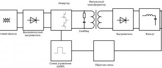
Switching bipolar power supply.
If you need a lightweight but powerful power supply, you will have to resort to rather complex pulse circuitry. Such a block can be assembled using field-effect transistors and an IR2153 microcircuit. The source provides power of about 100 watts, the output voltage is set by the transformer parameters. With the turns ratio indicated in the diagram, the output will be about 35 volts in each arm.
Step-by-step instruction
Assembly is carried out according to the drawn circuit diagram. The microcircuit was selected according to the characteristics of the circuit.
Assembly is carried out as follows:
- at the input .
- Then , a pair of capacitors is installed.
- Drivers are necessary to regulate the operation of the gates of field-effect transistors. If the drivers have a D index at the end of the marking, there is no need to install the FR107 diode.
- Field-effect transistors are installed without shorting the flanges. When attaching to the radiator, use special insulating gaskets and washers.
- Transformers are installed with shorted leads.
- The output is diodes.
Transformer manufacturing
Since we have a ring, most likely its edges will be at an angle of 90 degrees, and if the wire is wound directly onto the ring, the varnish insulation may be damaged, and as a result, an interturn short circuit and the like. In order to eliminate this point, the edges can be carefully cut with a file, or wrapped with cotton tape. After this, you can wind the primary.
After we have wound it, we again wrap the ring with the primary winding with electrical tape.
The difference between a CFL circuit and a pulse power supply
This is one of the most common electrical circuits for energy-saving lamps. To convert a CFL circuit into a switching power supply, it is enough to install just one jumper between points A - A' and add a pulse transformer with a rectifier. Elements that can be deleted are marked in red.
And this is a complete circuit of a switching power supply, assembled on the basis of a CFL using an additional pulse transformer.
To simplify, the fluorescent lamp and several parts were removed and replaced with a jumper.
As you can see, the CFL circuit does not require major changes. Additional elements introduced into the scheme are marked in red.
Return to top menu
Construction and details
All parts of the UMZCH and the power supply are placed on one board. The exceptions are transistors VTZ, VT4, VT6, VT8 UMZCH, installed on a common heat sink with a dissipating surface area of 1200 cm2 and transistors VT7, VT8 BP, placed on separate heat sinks with a dissipating surface area of 300 cm2 each.
Coils L1, L2 of the power supply (Fig. 3) and L1 of the power amplifier contain 30.40 turns of PEV-1 wire with a diameter of 1.0 mm, wound on the body of a resistor C5-5 or MLT-2. Resistors R7, R12 of the power supply are a piece of copper wire PEL, PEV-1 or PELSHO with a diameter of 0.33 mm and a length of 150 mm, wound on the body of the MLT-1 resistor.
The power transformer is made on a toroidal magnetic core made of electrical steel E320, thickness 0.35 mm, tape width 40 mm, internal diameter of the magnetic core 80 mm, outer diameter – 130 mm. The network winding contains 700 turns of PELSHO wire with a diameter of 0.47 mm, the secondary winding contains 2×130 turns of PELSHO wire with a diameter of 1.2 mm.
Examination
In order to correctly assemble the power supply, you need to be careful about installing the polar elements, and you should also be careful when working with mains voltage. After disconnecting the unit from the power source, there should be no dangerous voltage remaining in the circuit. If assembled correctly, no further adjustment is required.
You can check the correct operation of the power supply as follows:
- We connect it to the circuit, the output is a light bulb, for example, 12 Volts. At the first short-term start, the light should be on. In addition, you should pay attention to the fact that all elements should not heat up. If something gets hot, it means the circuit is assembled incorrectly.
- At the second start, we measure the current value using a tester. Let the unit operate for a sufficient amount of time to ensure that there are no heating elements.
Assembling the device
Let's start with etching the board (etching, stripping, drilling). Archive from PP.
First I bought some missing parts (transistors, IR, and powerful resistors).
By the way, the surge protector was completely removed from the power supply from the disc player:
Next, carefully solder the parts on the board according to the diagram and PP.
Now the most interesting thing about the SMPS is the transformer, although there is nothing complicated here, you just need to understand how to wind it correctly, and that’s all. First you need to know what and how much to wind; there are many programs for this, but the most widespread and popular among radio amateurs is ExcellentIT . This is where we will calculate our transformer.
As you can see, we have 49 turns of the primary winding, and two windings of 6 turns each (secondary). Let's rock!
Power calculation
Repeating a ready-made power supply design does not require calculations. Copying the diagram and precise selection of components guarantees the specified parameters. The need for calculations appears if other characteristics of the block are needed or if there is a need to use other parts. The greatest difficulty is in selecting the required ferrite and calculating the pulse transformer. When using online calculators, set all parameters in comparable units - volts, watts.