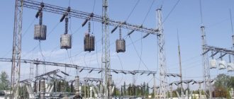
Electricity is one of the main energy sources in all developed countries. It’s hard to even imagine what will happen to the residents of a house where several hundred or even thousands of people live at the same time if the energy supply is disrupted. The inability to do the simplest housework, cook food, or spend free time comfortably - the entire usual way of life will simply be destroyed. That is why the power supply of an apartment building is a very important and responsible matter.
General diagram of power supply for any objects
What regulations regulate electricity supply in apartment buildings?
The legislation regulating the electricity supply system in MKD is systematically adjusted and is quite extensive. Let's get acquainted with some documentation that is directly related to the issue of power supply.
The electricity retail market is regulated by Federal Law No. 35-FZ dated March 26, 2003 “On Electric Power Industry”. The conditions for the provision of utility services for electricity supply in apartment buildings are adopted by the Rules for the provision of utility services to owners of residential premises and tenants of space in apartment buildings, approved by Decree of the Government of the Russian Federation of May 6, 2011 N 354. In accordance with Regulation No. 1 of these Rules, a permissible stop in the provision of utilities and acceptable inconsistencies in the quality of these utilities with the normative GOST 32144-2013, the conditions and process for adjusting the amount of payment for the provided utilities of poor quality and/or with interruptions that exceed the permissible time established at the legislative level.
For example, the possible duration of an interruption in the power supply of an apartment building belonging to the second reliability category (if there are two independent transformers) is 120 minutes, and for apartment buildings that belong to the third reliability category (there is only one transformer) - one day. For each hour that goes beyond the boundaries of the norm established at the legislative level, the amount of payment for utility services for the estimated time is reduced by 0.15% of the amount established for the given settlement period in accordance with Appendix No. 2, taking into account the paragraphs of the ninth section.
Typically, the power supply to MKD occurs through the main distribution board (MSB) or input distribution device (IDU). In this case, all subscribers are powered from a 220/380 V network with a solidly grounded neutral (TN-CS system). The main switchboard includes a circuit breaker and control devices that allow you to separately disconnect power consumers. The main switchboard distributes power supply voltage to group consumers (lighting of stairwells, basements, attics, elevator equipment, fire and emergency alarms, residential premises, etc.).
Electricity supply to residential premises is carried out through risers, through an RCD. Floor distribution panels are connected to the supply risers, forming a power supply network for the apartments. Floor electrical panels usually include electricity meters, circuit breakers and RCDs. Circuit breakers are grouped for each power supply circuit (lighting, sockets, electric stove, washing machine, etc.). To ensure an even load on the distribution network, the power circuits of different apartments are connected to different phase conductors.
Electrical installation requirements Safety
Any electrical installation should provide:
- protection against electric shock (grounding of accessible parts, double insulation, restriction of access to switchboards);
- the presence of automatic shutdown devices when differential currents occur, which helps protect people from indirect contact with live parts;
- overload and short circuit protection.
In order to ensure a high level of safety, the equipment used in low-voltage complete devices must comply with the requirements of current Russian and international standards.
Power supply categories
To better understand the differences in power supply schemes for a multi-storey building (both residential and any other), you need to know that power supply can be provided in different ways, differing significantly in reliability. The most difficult reliability category is the first. With it, residential buildings are powered by two cables. Each of them is connected to a separate transformer.
If one transformer or cable fails, the ATS (automatic transfer switch) device will immediately transfer all power to the working cable. Thanks to this, problems with the power supply will occur in a matter of seconds. After a group of electricians left and repaired the failed equipment, electricity supply is maintained as usual.
In order to correctly understand the various power supply schemes for residential buildings , you need to know about the three categories of ensuring the reliability of power supply to electrical installations. The simplest category is the third. It provides power to a residential building from a transformer substation via a single electrical cable. Moreover, in the event of an emergency, the interruption in the power supply to the house should be less than 1 day.
With the second category of power supply reliability, a residential building is powered by two cables connected to different transformers. In this case, if one cable or transformer fails, the power supply to the house while the fault is being eliminated is carried out through one cable. An interruption in power supply is allowed for the time necessary for the electrical personnel on duty to connect the loads of the entire house to the operating cable.
There are two types of power supply at home from two different transformers. Either the loads of the house are evenly distributed across both transformers, and in emergency mode they are connected to one, or in operating mode one cable is used, and the second is a backup. But in any case, the cables are connected to different transformers. If two cables are laid in the electrical panel of a house , one of which is a backup, but it is possible to connect these cables to only one substation transformer, then we have only the third category of reliability.
With the first category of power supply reliability, a residential building is powered by two cables, just as with the second category. But if a cable or transformer fails, the loads of the entire house are connected to the working cable using an automatic transfer switch (ATS).
There is a special group of electrical receivers (fire alarms, smoke removal systems in case of fire, evacuation lighting and some others), which must always be powered according to the first reliability category. For this purpose, backup power sources are used - batteries and small local power plants.
According to existing standards for the third category of reliability, electricity is supplied to houses with gas stoves with a height of no more than 5 floors, houses with electric stoves with the number of apartments in the house less than 9 and houses of gardening associations.
Electricity supply in the second reliability category applies to houses with gas stoves with a height of more than 5 floors and houses with electric stoves with more than 8 apartments.
According to the first reliability category, it is mandatory to supply electricity to heating points of apartment buildings, and in some buildings, elevators. It should be noted that the first category mainly supplies electricity to some public buildings: these are buildings with more than 2000 employees, operating rooms and maternity wards of hospitals, etc.
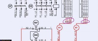
The figure shows the power supply diagram for four entrance houses, powered according to the second reliability category with a backup cable. The supply cables are switched using a reversing switch having positions “1”, “0” and “2”. In position "0" both cables are disconnected. The circuit breakers QF1...QF4 feed the lines that run along the access vertical risers, from which power is supplied to the apartments. General house loads: lighting of staircases, basements, lamps above the entrance doors to the entrances are powered by a separate group containing its own electricity meter.
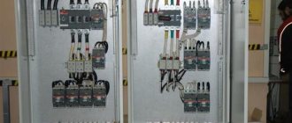
Depending on the number of apartments in the house, all electrical equipment can be placed in one electrical cabinet or in several.
List of further works
After the wiring diagram has been sketched out, we begin to calculate the network parameters and install it.
Selecting a cable and calculating its cross-section
To accurately calculate the cable cross-section based on the power of consumers, use the following relationship: I=P/U, where P is the total power of all consumers in the circuit for which the cross-sectional area of the conductor cores is selected, and U is the voltage of the apartment network. Most often, the wiring circuits are arranged in such a way that the electric current load in them does not exceed 25 A. In this case, the following sections are used:
- wire VVG-3*2.5 – two-core power cable with a cross-section of one conductor of 2.5 mm2. This is the most used wire for organizing the electrical network in the apartment. They connect the distribution board with the distribution boxes of the premises;
- wire VVG-3*1.5 - two-core power cable with a cross-section of one conductor of 1.5 mm2. Such conductors are used for installation from distribution boxes to sockets, automatic switches in the panel;
- wire VVG-3*4 – three-core power cable with a conductor cross-section of 4 mm2. Such conductors are separated into separate circuits for connecting powerful apartment consumers (furnace, heating tank, etc.).
Marking sockets and switches
The placement of sockets and switches in the apartment should ensure ease of use and cover the needs of residents in connecting equipment. A typical example of the layout of electrical equipment (connection points) is presented in Figure 6.
An example of placing connection points in an apartment
When marking the locations of sockets and switches, the following requirements of modern standards must be observed:
- sockets and switches are located to the left of the doors;
- switches are mounted at a height of 0.9 m from the floor;
- in living rooms, sockets are located at a height of 0.4 m from the floor, in the kitchen - 0.95 -1.15 m, in the bathroom the use of sockets is prohibited.
Wall chipping
After marking the locations of distribution boxes, sockets, switches, and installation points for lamps, they begin to arrange grooves (grooves) along the walls and on the ceiling for laying out the wiring. It is worth remembering that gating should be done in horizontal and vertical planes along straight lines. This will make it possible to more accurately determine the location of the wire in the future. The grooves are made using a grinder or a hammer drill. The depth of the groove must be at least 20 mm, and the width must be sufficient for laying all cables planned for laying in this location.
Cabling
The principles of laying cables for hidden and open wiring are the same. Installation starts from the connection points and leads to the distribution panel. Next, the line is inserted into the shield and moved to another circuit. If necessary, identification tags are hung on the end sections of the wiring for quick reference. After installation is completed, the cables are covered with boxes or putty in the wall.
Installation of socket boxes and junction boxes
The laid wiring is brought to the mounted junction boxes and electrical outlets, inserted into them, and the ends are driven out with a small margin. All wiring branches are arranged in boxes. The connection of the conductors of aluminum or copper wiring must be reliable. For connection, it is advisable to use special devices, as shown in Figure 7.
Connecting conductors in a junction box
Immediately before connecting the wires, they ring and make sure that the installation work is carried out correctly at this stage.
Installation and assembly of electrical panel
When all the cables of all electrical circuits are laid to the installation site of the electrical panel, they begin to organize the apartment's distribution panel. This part of the electrical network is characterized by a large number of conductors and protective devices, so it is very important to make all connections correctly. For the shield, you always choose mounting boxes with a certain supply of seats. This will allow you to upgrade the system or eliminate its malfunction in the future.
An example of an electrical panel diagram for a standard apartment is shown in Figure 8.
Figure 8. Example of electrical panel diagram
In the figure, the positions indicate: 1 - introductory machine; 2 - electric meter; 3 - zero bus; 4 — protective grounding bus; 5–9 — automatic machines; 10 - separate automatic switch for lighting
Installation of sockets and switches
Sockets and light switches are installed in pre-installed boxes with wire ends removed. The process is not difficult and will require a minimum set of tools: pliers, wire cutters, and a screwdriver. This is the final stage of installation work on the apartment’s electrical network.
Checking the quality of work
The quality of the work performed is checked by turning on the wiring circuits and checking the presence of voltage and the correct phase distribution in the network. This procedure is carried out using voltage indicators. Incorrect installation can also immediately show a disconnected circuit breaker against short circuits.
Ring diagram of power supply for an apartment building
Ring power supply diagram for an apartment building is a plan for installing and connecting electrical receivers, according to which power supply to an apartment building is possible via two cable lines forming a ring. This ring diagram looks like this:
The first and last electrical receivers are connected from the main power source, and so-called jumpers are created between all remaining electrical receivers.
To create such a ring plan, two changeover switches should be provided in the ASU for each apartment building.
In normal mode, the power is evenly divided between the two inputs.
In order to understand why this circuit requires exactly two switches, we let you consider a number of possible emergency situations:
- Failure of one of the supply cable lines
In such a situation, the power supply to all multi-apartment residential buildings comes from one cable line.
Specialists from the management company install the switches in the required position.
- Jumper failure
Workers are required to isolate from the power supply circuit the area where the accident occurred (for example, a short circuit occurred on the line). One part of the houses is powered by one cable line, and the second part of the residential buildings is powered by another. Instead of two changeover switches, you can use three regular ones.
Do I need to pay for the project?
It was already mentioned above that the cost of a power supply project for an apartment building is quite high. And many construction customers are seriously thinking: is it necessary to spend extra money when ordering design? Indeed, today there are dozens of sites on the Internet where you can download suitable projects for a wide variety of houses: from 4-apartment buildings to huge skyscrapers with hundreds of classrooms and offices. Using a ready-made project would save tens of days of work and tens (and maybe hundreds!) of thousands of rubles.
Electricity supply rules
The general rules for power supply to a residential building are regulated by Decree of the Russian Federation No. 354. The management organization ensures the provision of electricity to the consumer. Consumers must pay it on time.
To provide electricity supply, the following actions are carried out:
- Concluding an agreement with a local energy supply organization.
- Development of technical specifications.
- Drawing up a house electrification scheme with calculation of the power of the devices intended for use. This is necessary to determine the cable cross-section and calculate the optimal power reserve.
- Installation and sealing of the metering device, ASU.
- Cable installation.
- Equipment selection.
- Checking compliance and issuing an act of commissioning into the distribution zone.
- Receipt of the document: “Act of fulfillment of specifications” and an agreement for the provision of electricity.
Self-connection is prohibited. The supplying company provides its employees.
Power Quality (PE)
In a broad sense, CE is a set of its properties that determine the effect on electrical equipment and devices. The quality of electricity is assessed by such indicators as the levels of electromagnetic interference in power supply systems by frequency, effective voltage value, shape of its curve, etc. Poor CE indicators lead to many negative consequences. The most unpleasant things for civil infrastructure facilities are a reduction in the service life of equipment, failures in the operation of system elements, as well as additional losses of electricity.
Comfortable operation of all systems and loads of a civil building can be ensured by the use of devices that improve the quality of electricity. These include:
- uninterruptible power supplies (UPS), eliminating voltage sags;
- active filters that eliminate distortion of current and voltage curves;
- capacitor banks that compensate for reactive power and also eliminate voltage sags.
Payment for electricity supply
An agreement on the provision of services is drawn up with the management company with the rights and obligations of each party specified.
Payment for electricity can be made in cash or non-cash in various ways using:
- bank cards;
- translations;
- Internet services.
Payment documents are retained for 3 years. Advance payment is allowed. Payment is due by the 10th of each month. The basis is payment documents based on approved tariffs.
Who changes what
Some disputes arise regarding whether the circuit breaker is responsible for the meter. According to existing rules and observed practice, apartment protection circuit breakers up to the metering meter are replaced at the expense of general house funds.
Apartment metering meters are changed by the owner of the apartment, involving specialists from supplying organizations for replacement work. Or by notifying and involving specialists from the supplying organization on your own to accept the work and seal the new meter.
Replacement of the power supply cable is carried out according to the electrical design of the apartment, taking into account the allocated capacities for this apartment. Data on allocated capacity must be kept by the management company.
The allocation of additional capacity per apartment is issued according to existing rules. Independent allocation of additional capacity is punishable under the existing law.
Energy efficiency
The limitations and cost of energy resources force humanity to seriously think about their efficient use. “If you take a residential or office building, you can find many places for introducing energy efficient technologies. For example, centralized water supply, ventilation and heating systems. Pumping equipment with variable frequency drives in conjunction with control cabinets allows saving electrical energy and also reduces water consumption,” says Roman Marikhbein (GRUNDFOS). The second no less significant part that can be optimized is lighting and comfortable temperature in the rooms.
Maxim Ryabchitsky (ABB) is confident that in general, to improve the energy efficiency of building systems, it is necessary to reduce the level of reactive power and harmonics, optimally control pumps and fans, use frequency-controlled motors and transformers with low losses, and ensure proper control of lighting and indoor climate. The specialist cited the example of “Smart Home” systems, which today are widely used not only in apartments, but also in offices. Using modern Busch-PriOn controls from the ABB i-bus KNX range, energy consumption can be reduced by up to 40%.
Monitoring and dispatching
The electrical system of a modern building is a rather delicate and complex structure that requires highly qualified support. Therefore, the electrical network must have a dispatch system that has a direct connection with all elements of the power system and allows them to be monitored and controlled. The equipment used must provide early diagnosis of failures, include means that allow continuous monitoring of the installation and prevent emergency situations.
The installation of monitoring and dispatch systems is now a prerequisite for business centers and residential complexes of class “A” (luxury).
Unlike electrical installations of industrial enterprises, accidents in the power supply of urban infrastructure buildings do not lead to environmental disasters or loss of human lives. Therefore, civil engineering projects are given undeservedly less attention than enterprises. And as a result, ordinary consumers of electricity often find themselves alone with problems in their electrical panels. It is in our hands to change the situation and take care of a high-quality and safe power supply system for the city infrastructure.
ABB press service
1https://stat.2gis.ru/