Electrical machines › DC electric machines
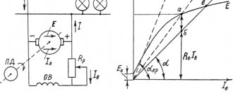
Independently excited DC motor (DPT NV) In this motor (Figure 1), the excitation winding is connected to a separate power source. rreg is included in the excitation winding circuit , and an additional (starting) rheostat Rп . A characteristic feature of the NV DPT is that its excitation current I depends on the armature current I, since the power supply to the excitation winding is independent.
§5.6. DC motors. Main characteristics
Motors of independent and parallel excitation. The circuit diagram for switching on an independent excitation motor is shown inAn additional resistance Rd can be included in the armature circuit, for example a starting rheostat. To regulate the excitation current, a control rheostat Rр can be included in the excitation winding circuit. In a parallel excitation motor, the armature and excitation windings are connected to the same power source, and the voltage on them is the same. Consequently, a parallel excitation motor can be considered as an independent excitation motor at Uя = Uв.
Mechanical characteristics. The mechanical characteristics of engines are usually divided into natural and artificial. The natural characteristic corresponds to the rated supply voltage and the absence of additional resistance in the motor winding circuits. If at least one of the listed conditions is not met, the characteristic is called artificial. The equations for electromechanical ω=f(I i) and mechanical ω=f(M em.) characteristics can be found from the equilibrium equation of EMF and voltages for the motor armature circuit, written on the basis of Kirchhoff’s second law:
U i=E i+I i)(R i+R d), (5.35)
where R i is the active resistance of the armature. Transforming (5.35) taking into account (5.6), we obtain the equation of the electromechanical characteristic
ω=(U i-I i(R i+R d))/kФ. (5.36)
In accordance with (5.10), the armature current I I = M em./kF and expression (5.36) is converted into an equation of mechanical characteristics:
ω=Uя/ kФ – ( R I+ R d)/( kФ) 2) Mem. . (5.37)
This equation can be represented as ω= ω o.id.- Δ ω, where
ω o.id.=Uя/kФ (5.38)
ω o.id - angular speed of ideal idle speed (at Iа=0 and, accordingly, Mem.=0); Δ ω= Ma'am. [(Rя+Rд)/(kФ)2] – reduction in angular speed due to the load on the motor shaft and proportional to the resistance of the armature chain. The family of mechanical characteristics at rated armature voltage and excitation flux and various additional resistances in the armature circuit is depicted in.
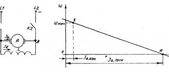
The mechanical characteristics of engines are usually assessed by three indicators: stability, rigidity and linearity. The natural mechanical characteristic corresponding to (5.37) at Rd=0 is depicted by straight line 1. The mechanical characteristic is linear; deviation from the linear law can be caused by the armature reaction, leading to a change in the flux F. This characteristic is rigid, since when the load torque and, accordingly, the speed change, the excitation flux does not change. The rigidity of the characteristic decreases with the introduction of additional resistance into the armature circuit (straight lines 2 and 3 are artificial rheostatic characteristics). The characteristics are stable, since dω/dMem.
Iya= (Uya-Eya)/(R i+ R d)=(Uya -kωФ;)/( R i R d), (5.39)
increases. Accordingly, the electromagnetic moment increases up to a new value of the moment of resistance (transition from point A to point B on the mechanical characteristic). By analogy, based on (5.37), a family of artificial characteristics can be constructed for various values of Uya or F. The analysis of such characteristics will be done in the section of DC actuator motors (§ 5.7).
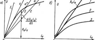
Performance characteristics. The operating characteristics of the engine are the dependences of the angular velocity ω, the electromagnetic Mem. and useful M2 torques and efficiency η from the useful mechanical power on the motor shaft P2=M2ω at the rated supply voltage and the absence of additional resistances (). However, for the motors under consideration, the performance characteristics are built not as a function of the useful power of the motor P2, but as a function of the armature current Iа. This is explained by the fact that in DC motors, the electrical power used for conversion into mechanical power is supplied through the armature circuit. The armature current of independent and parallel-excited motors, in which the speed weakly depends on the load, is almost directly proportional to the power P2. It is much easier to obtain equations for operating characteristics in terms of current Iа. Characteristics ω= f(Iя) and Mem.=а(Iя) can be constructed, respectively, based on equations (5.36) and (5.10). Without taking into account the armature reaction, these characteristics are linear; in real machines, under the influence of the armature reaction (change in F), the characteristics may turn out to be nonlinear. The useful component of the engine torque M2 is less than the electromagnetic torque by the value of the idle torque M0=(ΔPmech.+ΔPm)/ ω, where ΔPmech. – mechanical power losses (friction); Δ Pm – magnetic losses. The characteristics of the useful torque M2 and efficiency η begin from the real no-load point, which corresponds to the armature current Iао (Fig. 5.20, b). The efficiency curve has a typical character for all electric machines, because in the motor there are constant losses (ΔPmech.+ΔPm+UvIv), practically independent of the load (armature current), and variable losses in the armature I 2ya Rya.
Speed regulation. The angular speed of the motor at a constant moment of resistance can be adjusted (see (5.37)) in three ways: 1) armature - by changing the voltage on the armature winding Ui; 2) pole – change in magnetic excitation flux Fv; 3) rheostatic - changing the additional resistance Rd in the armature circuit. The regulating characteristics of independent excitation motors with armature and pole control methods will be discussed in detail in the section of actuator motors (see §5.7). With the rheostatic method, a significant current must be passed through the rheostats Rd (see) for a long time, which causes large power losses, therefore this method is uneconomical and is rarely used.
Start. In accordance with the moment equilibrium equation (2.29), the condition for starting the engine is the inequality Mn > Mst. If this condition is met, then when the engine is turned on, the rotor starts to move and accelerates to a steady state. Due to the fact that the rotor has a moment of inertia, it does not accelerate instantly - the speed increases according to a law close to exponential. Starting a DC motor is complicated by the fact that at ω=0 EMF EIa=0 and the starting armature current IaP= UIa/ RIa can be 10 - 20 times higher than the rated current, which is dangerous both for the motor (increased sparking, dynamic overloads) and for the power supply. Therefore, the most important indicators of the starting mode are the multiplicity of the starting current Kip = Ip/ Inom and the multiplicity of the starting torque Kmp = Mp/ Mnom. When starting, it is necessary to ensure the required multiple of the starting torque with the lowest possible multiple of the starting current. Direct starting is usually used with a starting current multiplicity of K iп?6. At a higher value of Kip, starting methods are used that ensure a reduction in current Iap either by applying a reduced voltage to the armature winding, or by introducing additional resistance into the armature circuit. The first method is used mainly when operating engines in automatic control systems with an anchor control method. The second method, called rheostatic, is most widespread in unregulated drives. The resistance of the starting rheostat Rп = Rд (see Fig. 5.19) is chosen so as to limit Ir to (1.4 - 1.8) Ir.nom for engines of medium power and to (2.0 - 2.5) Ir.nom for low power engines. As the armature accelerates, the armature current decreases and the starting rheostat is gradually removed.
Reversing. Reversing the motor is carried out either by changing the polarity of the voltage on the armature winding or on the field winding. In both cases, the sign of the electromagnetic torque of the MEM engine and, accordingly, the direction of rotation of the rotor changes.
Braking. For independent and parallel excitation motors, three braking modes are possible: regenerative braking, counter-switching braking and dynamic braking. When analyzing braking conditions, it is necessary to construct the mechanical characteristics of the machine in all four quadrants of the plane Mem, ω. To construct mechanical characteristics, you can use the same equation (5.37), taking into account the sign of Mem in different operating modes of the machine. Regenerative braking, or regenerative braking with energy released into the network, can be carried out at ω>ω o.d. In this case, the armature EMF Eя > Uя (see (5.6) and (5.38)), the armature current changes direction, the machine goes into generator mode and the electromagnetic torque becomes braking. The mechanical characteristic in the regenerative braking mode is the continuation of the mechanical characteristic of the engine in the II quadrant (ω>0, Mem (Fig. 5.21, a, Uя2я1).
At the moment the supply voltage decreases, the engine moves from point A of characteristic 1 to point B of characteristic 2, the moment Mem changes sign and the engine begins to brake to point C. Braking to a stop in this way is impossible and it is used mainly when braking at high speeds. The method is economical due to the possibility of transferring electrical energy to the network. Braking by counter-switching can occur in two cases: 1) if an external torque greater than the starting torque of the engine causes the armature to rotate against its natural direction of rotation (operation in the IV quadrant); 2) if the polarity of the voltage on the armature (or less often on the excitation winding) changes, and the armature, by inertia, continues to rotate in the same direction. Next, we consider the most common second case with a change in the polarity of the voltage at the armature. In this case, the armature current Iа=(-Uя- Eя)/ Rя changes direction and its value increases sharply, because Now voltage and emf act in the same direction. Therefore, when braking by counter-connection, an additional resistance Rd is necessarily included in the armature circuit. A change in the polarity of the voltage on the armature means that the sign of the ideal speed will also change. ω o.id, i.e. the mechanical characteristic will pass through the III quadrant (). At the moment of voltage switching, the engine moves from point A of the natural characteristic of motor mode I to point B of the rheostatic characteristic of braking mode 2, the torque Mem changes sign and an intensive decrease in ω begins. At point C, the motor speed is zero and it must be disconnected from the power source. If this is not done, then the rotor will begin to rotate in the opposite direction and will go into steady state at rheostatic point D or, if Rd is turned off, at point D' of the new natural characteristic 3, i.e. the engine will reverse. Dynamic braking is carried out by disconnecting the armature circuit from the direct current source U and closing it to some additional resistance Rd, usually called a braking rheostat (transferring switch K from the left to the right position).
In this case, the voltage applied to the armature, Ui=0, the armature current (see 5.39) Ia=-Eya/(Rya+Rd) changes direction and the electromagnetic torque Mem becomes braking. The kinetic mechanical energy stored in the rotating parts of the drive is converted into electrical energy, and the machine operates in generator mode, delivering electrical energy to the braking resistances. The equation of mechanical characteristics (5.37) at Uя=0 takes the form ω=-Мем(Rя+Rд)/(kФ)2. The mechanical characteristics of the braking mode are located in the II quadrant of the plane Mem,ω (, Rд2>Rд3). At the moment of switching, the engine moves from point A of the natural characteristics of the motor mode 1 to point B of the characteristics of the braking mode 2, the moment Mem changes sign and dynamic braking begins. The angular velocity decreases, but at the same time the braking torque also decreases quite sharply (transition from point B to C). In order to increase the braking torque, the additional resistance Rd is reduced (transition from point C to point D). Braking occurs to zero speed.
Motors of series and mixed excitation. In a series-excited motor (), the armature current flows through the excitation winding (Iв = Iя) and this in a certain way affects the main characteristics of the motor. In the absence of saturation of the magnetic circuit, it can be assumed that
Ф=KфIя, (5.40)
where Kf is the proportionality coefficient. Taking (5.40) into account, equations (5.10) and (5.37) take the form
Mam=KKфIя2, (5.41)
ω = (U/ √(KKfMem)) -(Rя+Rв/KKф), (5.42)
where Rв is the resistance of the excitation winding. The mechanical characteristic (dashed line) is soft, has a hyperbolic shape and ensures stable engine operation. The softness of the characteristic is explained by the fact that with an increase in load torque and a corresponding decrease in speed, the current and excitation flux increase. At high loads, saturation of the magnetic circuit begins to affect and the characteristic differs from the calculated one (solid line). The sequential excitation motor cannot be started without a load on the shaft, since at Mem → 0, the angular velocity ω → ∞. The quadratic dependence of torque on current makes it possible, with the same multiplicity of starting current, to obtain a larger starting torque from a series-excited motor than from an independent or parallel-excited motor. Starting, reversing, braking and regulating the angular speed of series-excited motors is carried out in the same ways as for independent and parallel-excited motors, taking into account the specifics of switching on the windings.
Mixed excitation motors, in their characteristics, occupy an intermediate position between independent and sequential excitation motors. The specific type of characteristics depends on whether the excitation windings are connected in accordance with or countercurrently (along the flow).
Back | Contents | Forward
Application of a megohmmeter
You can check the winding using such a device by following the small rule indicated below:
- when the supply voltage is less than 500 V, you need to use a device with a suitable rating;
- if the voltage is 500 V or slightly more, you need to choose a megohmmeter whose operating voltage reaches 1000 V.
ATTENTION! For equipment whose operating voltage is designed for 600 V, it is imperative to use a megohmmeter that can withstand 2500 V.
Measurements of the windings relative to the motor housing are carried out one by one. Check each circuit with different terminals. All remaining ends must be connected to the body. If the motor is three-phase, a similar algorithm is carried out for each of the three components of the electric motor.
Microcontroller
ATMega328p, operating at a frequency of 16 MHz, was selected as the control microcontroller.
The microcontroller is connected to a Chinese clone of Arduino Nano v3 ($1.5). The microcontroller generates a PWM signal through an eight-bit counter with a divider of 8, so the frequency of the PWM signal is 16 * 10^6 /255 /8 = 7.8 kHz, which fits within the maximum 20 kHz available to the driver.
The microcontroller ADC divider is set to 128; Since each measurement requires approximately 13 clock cycles, the maximum frequency of current flow measurements is approximately 16 * 10^6 / 128 / 13 = 9.6 kHz. Measurements are made in the background, notifying the main program of completion by calling the appropriate interrupt.
Resistance measurement using increased AC voltage
To carry out such a test, you need a linear converter (in other words, a transformer). It will be a source of increased voltage, since it is equipped with a control device that allows you to set a specific potential level for testing. To carry out such tests, increased voltage will be required, obtained from a linear converter (transformer). The latter is equipped with an adjustment device that allows you to obtain the desired level of test potential. In addition to the transformer, the installation diagram also requires a switch and a current protection device. This helps the transformer to switch off if a breakdown occurs in one of the secondary winding circuits or the insulation protection is destroyed.
To test the main insulation, the voltage is applied for one minute, and for the interturn test - for five minutes. If a high-voltage potential is applied for a short time, the insulation state will not change in any way, i.e. its protective properties do not deteriorate.
High Voltage Motor Insulation Test
ATTENTION! When the voltage increases to a third of the initial test value, it is not necessary to take into account the dynamics of the process.
When a third of the desired voltage has been reached, begin increasing very gradually. The feed rate should be such that it is easy to visually record the instrument readings. At the same time, when you have reached half the required voltage, you need to finish feeding to the desired mark in at least 10 seconds.
Short circuit test
Another popular failure of electric motors, regardless of model and type, is a short circuit. To identify it, you need:
- set the maximum value of the measured resistance;
- connect one of the probes to the body;
- The second of the probes is connected in series to the output of all phases.
High resistance values (hundreds and thousands of megaohms) as a result of such a test indicate the serviceability of the electric motor.
If you perform the same actions in the “Ringing” mode, the sound of the multimeter will indicate the presence of a winding violation and the presence of a short circuit. Such a breakdown can not only damage the engine, but also become a threat to human life.
Detection of inter-turn short circuit
The third, one might say, standard failure is an interturn short circuit. This is the name given to the process of short circuit that occurs between the turns on one coil of an electric motor. The problem is characterized by a strong hum of the engine and a noticeable decrease in power. To identify a problem of this type, a current clamp or the same multimeter is usually used. During diagnostics with current clamps, it is necessary to measure the current value in each phase. Have you found a place where it is overpriced? There is a short circuit there.
If the electric motor wires are covered with a special film, but under other normal conditions the resistance will show the same value for a very long time. But exploitation leaves its mark, and protection may be affected by some destructive factors. Below are the main ones:
- mechanical damage (impacts, falls, etc.);
- the environment where the engine was located for a long time had high humidity;
- the environment where an electric motor is constantly located is characterized by the presence of aggressive chemicals;
- The temperature in the environment where the engine is located often fluctuates.
Additional influencing factors: if the motor runs more than specified in the instructions, its overheating can negatively affect the condition of the winding.
Everything listed below negatively affects resistance indicators. This is followed by a breakdown of the winding to the housing, and an interphase short circuit occurs.
If defects in the operation of a DC electric motor are not identified in time, they can lead to additional repair work, with large costs of labor and money. This is especially true for resistance in the motor windings. Problems with this characteristic not identified in time can lead to complete failure of the unit and even a fire. To avoid the unfortunate consequences of a malfunction, the resistance can be checked using a megohmmeter, voltmeter and ammeter, using increased voltage and much more.
Measurements using a bridge and a modern digital ohmmeter
Each device that you are going to use has instructions. If you haven’t saved it after purchasing, all the necessary information can be easily found on the Internet. And you will need it, because all measurements using this method must be done strictly according to the described rules.
The measuring bridge circuit has resistors: constant and variable. They are connected in such a way that two so-called shoulders are formed; they look like two chains. There will be free space in the second half. There they turn on the resistance, the value of which is to be measured.
A device – a digital ohmmeter – is included in the diagonal of the measuring bridge. By changing the value of the variable resistance, you can achieve a state where the current flowing through the “shoulders” is the same. The resistance that is being sought is calculated by the ratio of three values: two constant resistances and one variable (it is obtained as a result of measurements using a device).
Digital ohmmeter
A digital ohmmeter is a new generation electronic device. With its help, it became possible to measure resistance over a wide range.