Automation of lighting supply in an apartment, house or street is achieved through the use of photo relays. If configured correctly, it will turn on the light when it gets dark and turn off during daylight hours. Modern devices contain a setting that allows you to set the trigger depending on the light level. They are an integral part of the “smart home” system, taking on a significant part of the responsibilities of the owners. The photo relay circuit first of all contains a resistor that changes the resistance under the influence of light. It is easy to assemble and configure with your own hands.
Operating principle
The connection diagram for a photo relay for street lighting includes a sensor, an amplifier and an actuator. Photoconductor PR1 changes resistance under the influence of light. At the same time, the magnitude of the electric current passing through it changes. The signal is amplified by a composite transistor VT1, VT2 (Darlington circuit), and from it goes to the actuator, which is the electromagnetic relay K1.
In the dark, the resistance of the photosensor is several mOhms. Under the influence of light it decreases to several kOhms. In this case, transistors VT1, VT2 open, turning on relay K1, which controls the load circuit through contact K1.1. Diode VD1 does not allow self-induction current to pass when the relay is turned off.
Despite its simplicity, the photo relay circuit is highly sensitive. To set it to the required level, resistor R1 is used.
The supply voltage is selected according to the relay parameters and is 5-15 V. The winding current does not exceed 50 mA. If it is necessary to increase it, more powerful transistors and relays can be used. The sensitivity of the photo relay increases with increasing supply voltage.
Instead of a photoresistor, you can install a photodiode. If a sensor with increased sensitivity is needed, circuits with phototransistors are used. Their use is advisable in order to save electricity, since the minimum response limit of a conventional device is 5 lux, when surrounding objects are still distinguishable. The threshold of 2 lux corresponds to deep twilight, after which darkness sets in 10 minutes later.
It is advisable to use a photo relay even with manual lighting control, since you can forget to turn off the light, and the sensor will “take care” of this on its own. It is easy to install and the price is quite affordable.
Step-by-step installation instructions
Right away I would like to move a little away from the topic and advise you to simultaneously connect a photo relay and a motion sensor for lighting. When paired, these two devices will allow you to turn on the lamp when darkness falls, only if a person appears in the detection zone. If there is no one on the site, the lights will not light up, which will significantly save energy.
The installation method depends on what protection class and type of mounting of the twilight light switch you purchased.
Today there are various manufacturing options, namely:
- with mounting on a DIN rail, on a wall or on a horizontal surface;
- outdoor or indoor use (depending on IP protection class);
- photocell built-in or external.
In the instructions, we will provide an example of installing a photo relay for street lighting with wall mounting. The connection is made at the stand for convenience, especially since this is just an example.
So, in order to connect the photo relay to the lamp yourself, you must complete the following steps:
- We turn off the power at the input panel and check the presence of current in the distribution box from which we will run the wire.
- We stretch the power wire to the installation site of the photo relay (next to the lighting fixture). We recommend that you use a three-core PVS wire to connect the twilight switch, which has proven itself to be a reliable and not too expensive conductor option.
- We strip the conductors of insulation by 10-12 mm in order to connect them to the terminals.
- We create holes in the housing for inserting the cores in order to connect the photo relay to the network and the lamp.
- To increase the tightness of the case, we attach special rubber seals in the cut holes to protect against dust and moisture getting inside. By the way, the twilight switch must be placed in such a way that the inlet holes are at the bottom, which will prevent moisture from penetrating under the cover.
- We connect the photo relay for street lighting according to the electrical diagram that we provided above. As can be seen in the photo, the input phase is connected to connector L, and the input neutral to N. A separate screw terminal with the appropriate designation is provided for grounding.
- We cut off the required length of wire to connect the photo relay to the light bulb (in reality, it could even be an LED spotlight). We also strip the insulation by 10-12 mm and connect it to terminals N' and L', respectively. The second end of the conductor is brought to the light source and connected to the terminals of the socket. If the lamp body does not conduct current, grounding does not need to be connected.
- Installation and connection are completed, let's move on to setting up the photo relay with our own hands. There is nothing complicated here; the kit includes a special black bag, which is necessary to simulate night. On the body of the light sensor you can see a regulator (signed with the abbreviation LUX), which is used to select the light intensity at which the relay will operate. If you want to save energy, set the rotary control to minimum (o). In this case, the signal to turn on will be given when it is completely dark outside. Usually the regulator is located next to the screw terminals, a little to the left and above (as shown in the photo).
- The last step of connecting the photo relay is to attach the protective cover and turn on the power on the panel. Once you do this, you can proceed to testing the device.
That's all I wanted to tell you about how to install and connect a photo relay with your own hands. We also recommend that you watch a visual video lesson, which shows in detail the entire essence of electrical installation.
Instructions for connecting a Feron photo relay
Finally, it should be said about which manufacturers of twilight switches are of the highest quality. Today it is recommended to give preference to products from companies such as Legrand, ABB, Schneider electric and IEK. By the way, the latter company has a fairly reliable model - FR-601, which has many positive reviews on the forums.
Characteristics of photocells
The choice of photo relay is determined by the following factors:
- photocell sensitivity;
- supply voltage;
- switching power;
- external environment.
Sensitivity is characterized as the ratio of the resulting photocurrent to the external light flux and is measured in μA/lm. It depends on frequency (spectral) and light intensity (integral). To control lighting in everyday life, the last characteristic is important, depending on the total luminous flux.
The rated voltage can be found on the device body or in the accompanying document. Foreign-made devices may have different supply voltage standards.
The load on its contacts depends on the power of the lamps to which the photo relay is connected. Lighting photo relay circuits can provide for direct switching of lamps through sensor contacts or through starters when the load is high.
Outdoors, the twilight switch is placed under a sealed transparent cover. It provides protection from moisture and precipitation. When working in cold periods, heating is used.
Photo relay and its operating principle
An effective device allows you to control energy costs and control lighting according to the required mode. Photo relays are used to timely turn on and off street lights, which is important for private homes. For this purpose, the device has a light-sensitive sensor. The element is connected to the food chain. When light rays hit the sensor, it becomes an insulator, and in the dark, the device conducts electricity to the lighting device. This is how a photo relay works, turning off the lights in daylight and turning them on in the absence of sunlight.
Compact photo relay has a simple design
Lighting: use of photo relay
The lighting control device is used in private homes, placed on lanterns along paths or near the front door. In a park, large suburban area and other spacious areas, photo relays are also used. The device is practical for lighting parking lots, courtyards, advertising structures and the visibility area of outdoor surveillance cameras. In all cases, an automated system is created that turns on the light when darkness falls. This allows you to save energy resources and ensure comfort in the desired areas.
The motion sensor can complement the photo relay
Characteristics of photo relay
When choosing a device for lighting control, its characteristics are taken into account. Manufacturers produce a wide range of devices that differ in appearance, characteristics, rated supply voltage and other parameters. Therefore, when choosing, you should pay attention to the following features of the photo relay:
- weight and dimensions of the device;
- temperature restrictions during operation;
- response sector;
- power and energy consumption level;
- network frequency for operation;
- rated voltage for supply.
Devices are also divided according to the type of switched lamps. Simple models are often designed to work with conventional incandescent or halogen lamps. For other lamp options, you should choose a photo relay whose power and characteristics correspond to the parameters of the light source.
Photo relay FR-2
Factory-made models are widely used in automation devices, for example, to control street lighting. You can often see lights burning during the day that you forgot to turn off. With photo sensors, there is no need for manual lighting control.
The industrially manufactured photo relay circuit fr-2 is used for automatic control of street lighting. Here also the switching device is relay K1. The FSK-G1 photoresistor with resistors R4 and R5 are connected to the base of transistor VT1.
Power is supplied from a single-phase 220 V network. When the illumination is low, the resistance of FSK-G1 is large and the signal based on VT1 is not enough to open it. Accordingly, transistor VT2 is also closed. Relay K1 is energized and its operating contacts are closed, keeping the lamps lit.
When the illumination increases to the operating threshold, the resistance of the photoresistor decreases and the transistor switch opens, after which relay K1 turns off, opening the lamp power circuit.
DIY photo relay circuit, connecting FR-601, 602, FR-75A
Capacitive photo relay for street lighting is a device that allows you to turn on or off lamps used on roads, at entrances and in parks. Their use saves energy and minimizes inconvenience for drivers, home residents and ordinary passers-by.
The work is based on a photoresistor or photodiode - semiconductor elements that change their parameters depending on the intensity of ambient light. During the day, when there is sufficient light, the light sensor opens the circuit and the lamp turns off, and at night the reverse sequence of actions occurs: the capacitive relay for controlling the lighting reduces the resistance and the light turns on.
Installation of photo relay
It is not difficult to install a photo relay with your own hands; it is only important to exclude the direct influence of the adjustable light source and protect the device from adverse external influences: moisture, direct sunlight, temperature changes.
For industrial devices, there are a number of standards that such solutions must comply with: GOST (domestic) and IP (international). It is more difficult to ensure that a homemade photo relay is protected from environmental factors, although it is theoretically possible. But for those who want to install such a device in their yard, near their entrance or garage, it is better to first consider the solutions offered on the market - without having the necessary knowledge and experience, it will be extremely difficult to bring the photo sensor to working condition with your own hands.
FR-601 (602)
When it comes to using standard single-phase photo relays for lighting, the most popular model is the FR-601 and FR-602 devices manufactured by IEK.
They are quite reliable, and even users uninitiated in electronics have no questions about how to connect an automatic backlight controller. These two modifications have minor differences: they both operate with current of the same voltage and frequency, have similar power consumption (0.5 W) and absolutely identical delivery kits.
The differences relate only to the maximum cross-section of the connected conductors: for the 601 model it is 1.5 square meters. mm., and for 602 - 2.5. Consequently, their rated load current is also different: 10 and 20 A, respectively. Both models have a built-in photocell; it can be adjusted from 0 to 50 lux in increments of 5 lux.
Making at home
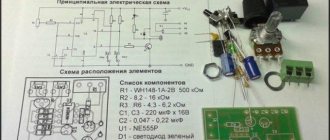
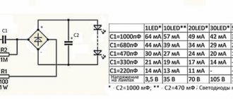
The schematic diagram of the FR-602 capacitive photorelay (like its brother) is easily repeated even with little knowledge of electronics. Creating a homemade product becomes especially relevant when there is a need for a large number of devices (for example, to organize automatic switching on and off of lighting depending on the time of day).
For manufacturing you will need the following parts; the designation on the diagram and power will be indicated in brackets:
- 2 bipolar transistors BC857A (Q1 and Q2);
- 5 rectifier diodes 1N4007;
- rectifier diode 1N4148;
- Zener diode 1N4749;
- resistors (R2, R4–R9: 1.5 MΩ, 1 MΩ, 560 kΩ, 200 kΩ, 100 kΩ, 75 kΩ and 33 kΩ; all 0.125 W);
- resistor (R3, 220 Ohm, 2 W);
- photocell (PH, up to 100 kOhm);
- trimming resistor (WL, 2.2 mOhm);
- capacitor (C2, 0.7 µF 400 V);
- electrolytic capacitors (C4–C5, 100 μF 50 V and 47 μF 25 V, respectively);
- relay SHA-24VDC-SA (Rel1).
Considering the set and total cost of parts, as well as the availability of a diagram, model 602 is a fairly simple solution to implement.
By the way, many parts from the list can be replaced with domestic ones. According to reviews from those who have already assembled, the bipolar transistor Q2 can be replaced with the ubiquitous KT3107B, and the zener diode 1N4749 can be replaced with three series-connected D814A or two D814D. The connection diagram is also not particularly complicated.
Disadvantages of the model
Let's look at the disadvantages of such a scheme. Oddly enough, from a technical point of view, the circuit is not inferior to the factory one with the proper skill of a radio amateur. The difference will be felt in actual use: the factory product has an IP44 protection standard, which means dust and moisture protection.
Also, factory FR-601 and FR-602 have a larger operating temperature range, and a homemade circuit in the cold in December may stop working due to a single poor-quality connection.
Analogs
Among the analogues of this device are the FR-75A - a photo relay, the circuit of which is more complex for manufacturing at home, and is also less stable and durable in practical use.
Among its advantages is a larger range of operating brightness, ranging from 1 to 200 lux, which is four times higher than its competitor. Another big advantage of the FR-75 device is the ability to operate in 12 V DC circuits.
Also, the photosensor is remote, which allows you to install the regulator itself indoors and not worry about environmental factors. In general, the model has no equal in its class and is the best photo relay - 12 volts DC is often used as power for such devices. The device connection diagram is shown in the figure.
High power equipment
Among the competitors, you can also consider the FR-7E photo relay, but the lack of moisture protection (IP40) and rather high power consumption are not in its favor.
Disadvantages also include open contact clamps and lack of protection for the trimming resistor on the front panel. A positive point is that the FR-7 can operate in AC networks of 220 volts with a voltage of up to 5 amperes, which is almost an order of magnitude greater than that of the competitors discussed above. The adjustment range of 10 lux is also set only by a specialist; you cannot adjust it yourself.
In terms of dimensions, the FR-7 also exceeds the photo relays discussed in the article (see drawing).
Conclusion
Taking into account the experience of operating photo relays in domestic and industrial conditions, the most stable and easily reproducible at home is the FR-602 model or its less powerful variation FR-601 from AIK. They perform well in various operating modes, have a good durability margin and, most importantly, have a minimum cost. In addition, their assembly is facilitated by the ability to replace many foreign parts with cheap domestic analogues.
Video
profazu.ru
Types of photo relay
The choice of models is large enough so that you can choose the right one:
- with a remote sensor located outside the product body, to which 2 wires are connected;
- Lux 2 - a device with high reliability and quality level;
- photo relay with a 12 V power supply and a load not exceeding 10 A;
- module with a timer mounted on a DIN rail;
- IEC devices from a domestic manufacturer with high quality and functionality;
- AZ 112 - automatic machine with high sensitivity;
- ABB, LPX are reliable manufacturers of European quality devices.
Application, pros and cons of use
The scope of application of such devices is quite wide; they are most often used for the following purposes:
- Automatic switching on of street lights in the darkest places.
- Illumination of facades of various buildings.
- Lighting of summer cottages in the evening and at night.
- Increasing the visibility range of video surveillance systems at late times or in dark places.
- Providing lighting in courtyards of residential areas.
The use of photo relays has recently become increasingly popular, and such systems are gradually becoming more widespread, this is due to the following significant advantages:
- Independent activation and the ability to manually regulate the parameters of this process is financially beneficial, since it allows savings when paying bills for consumed electricity.
- There are some varieties of such devices, for example, those with a photocell built into the design, which have a fairly simple installation and connection scheme. This allows you to independently organize the installation of the device without involving qualified specialists in this process.
- Some models are equipped with timers, this increases their cost, but allows for significant savings during operation, since the individual mode allows you to automatically turn on the lighting only at those moments when it is necessary.
- Automatic execution of all necessary actions by the device. At the same time, a number of more complex modern models allow you to start lighting only if the device detects any movements. This happens due to the presence of special sensors in the design.
- Increased security level, since automatically switched on lighting creates the illusion of the presence of people and can scare away intruders.
Such devices do not have any significant disadvantages, except for the fact that they will require some expenses. However, taking into account all the advantages and convenience of such systems, this minus is insignificant, and the photo relay compensates for all expenses with its work.
Methods for connecting a photo relay
Before purchasing a sensor, you need to calculate the power consumed by the lamps and take it with a margin of 20%. With a significant load, the circuit of a street photo relay provides for the additional installation of an electromagnetic starter, the winding of which must be switched on through the contacts of the photo relay, and switch the load with power contacts.
This method is rarely used at home.
Before installation, the supply voltage of ~220 V is checked. The connection is made from a circuit breaker. The photo sensor is installed in such a way that the light from the flashlight does not fall on it.
The device uses terminals to connect wires, which makes installation easier. If they are missing, a junction box is used.
Thanks to the use of microprocessors, the connection diagram of the photo relay with other elements has acquired new functions. A timer and a motion sensor were added to the action algorithm.
It is convenient when the lamps automatically turn on when a person passes along a landing or along a garden path. Moreover, operation occurs only in the dark. Due to the use of a timer, the photo relay does not react to headlights from passing cars.
The simplest connection diagram for a timer with a motion sensor is serial. For expensive models, special programmable circuits have been developed that take into account various operating conditions.
Three-wire motion sensor connection diagram
Three terminal sensors are typically used in IR sensor type designs. A fairly common manufacturer of inexpensive infrared motion sensors is IEK. You can find good products on Aliexpress without any problems.
More expensive products are made according to a similar principle; the connection diagram for a lamp with a sensor is similar for a sensor model from any manufacturer. Devices must have a degree of protection IP44 against penetration of solid objects greater than 1 mm and drops of moisture. If the motion sensor needs to be moved outside the house, then installation is only possible under a canopy.
If you want to protect the device from rain and snow, look for a model with IP65 dust and moisture protection and a temperature rating for your climate. Most IR sensors can only operate down to minus 20 degrees Celsius.
To connect a three-wire IR motion sensor, a full phase and zero are started. For correct placement you will need the same basic 4 elements:
- Circuit breaker (which is in the switchboard).
- Distribution box (in which the main installation).
- Sensor (a wire from the junction box is connected to it).
- Lamp (second wire from the junction box).
The sensor is connected with three wires to the factory in the distribution box of three cables:
- There are three wires from the machine: L (phase), N (working zero), protective zero or ground (PE).
- There are three wires per lamp if the body of the lighting fixture is made of metal.
- Three wires per sensor.
How to connect a motion sensor to a light bulb using three wires is discussed in detail in the diagram.
The zeros (N) are collected at one point (as in the case of the previous diagram). The ground from the circuit breaker is also connected to the luminaire ground (zero drive or PE). The motion sensor with three terminals is now supplied with phase-zero:
- Two input ones are for 220V power supply, usually labeled as L (phase) and N (zero).
- One output is designated by the letter A.
Installation
To install a three-wire motion sensor:
- Unscrew the two screws in the housing. The terminals are located under the back cover.
- Some models are already led out of the housing by three wires of different colors. By color you can determine what it means: ground (A) red, zero (N) blue, phase (L) brown. But if the cover opens without much effort, it is recommended to verify the correctness of certain markings in person by looking at the inscriptions next to the terminals.
- A simplified diagram of connecting a motion sensor to a light bulb looks like this:
- A little clarity in this picture.
- You can do without a junction box for connecting wires and run all the wires directly into the sensor box, if the inside is spacious enough and has its own terminal block. Phase-zero was supplied from one cable, and phase-zero was removed from the other.
- The result is a simplified, but the same three-wire circuit, only without a junction box.
Setting and adjusting sensitivity
After successfully connecting a lamp with a motion sensor, you need to set its parameters correctly:
- On the back of the case, find the main controls. LUX with the positions of the month and the sun is responsible for triggering depending on the illumination. Do you need the sensor to turn on in a room with a window only when it is cloudy or the sun goes down? Turn the regulator towards the moon.
- Use the second regulator to set the shutdown time. The delay can be set from a few seconds to 5-10 minutes.
- The rotation angle of the entire sphere allows you to adjust the detection of animals.
Advantages and nuances of use
To prevent the sensor from reacting to animals, do not turn the sensor head down towards the floor. Position it so that it captures the movements at the level of the head (shoulders) of all residents of the house. Typically, animal capture does not occur at this level.
If you need the sensor to temporarily not work, then point its head at the ceiling. Therefore, motion capture is not possible. The sensor's motion capture depends on the angle of inclination. In reality, the maximum distance reaches 9 meters. But according to the passport it may be higher.
The sensor uses infrared rays for detection. If you move from beam to beam, the device notices activity and reacts. When you walk directly into the beam, the sensitivity of the sensor is minimal and the device may not immediately respond to you.
For this reason, motion sensors are installed not directly above the doorway, but slightly to the side. For example, in the corner of the room.
Flaws
The disadvantage of the three-wire circuit for connecting the motion sensor to the lamp is that the light does not turn on forcibly. If the sensor malfunctions for some reason, problems will begin with its correct operation. To avoid this, it is recommended to add a switch to the circuit.
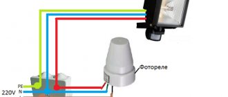
Photo relay for street lighting
To connect the photo relay, the circuit is applied to its body. It can be found in the documentation for the device.
Three wires come out of the device.
- Neutral conductor - common for lamps and photo relays (red).
- Phase - connects to the device input (brown).
- Potential conductor for supplying voltage from the photo relay to the lamps (blue).
The device operates on the principle of phase interruption or phase switching. Color markings may vary from manufacturer to manufacturer. If there is a ground conductor in the network, it is not connected to the device.
In models with a built-in sensor, which is located inside a transparent case, the street lighting operates autonomously. You just need to supply power to it.
Options with remote sensors are used when the electronic content of the photo relay is conveniently placed in the control panel with other devices. Then there is no need for stand-alone installation, power wiring and maintenance at height. The electronic unit is placed indoors, and the sensor is taken outside.
General principles for installing light switches
Installation of a simple lighting system and control devices is carried out during renovation work in the room. For hidden wiring, before finishing finishing work, the cable is laid in grooves and places are prepared for the installation of switches. In this case, switching of switches, lighting devices and power lines is carried out in installation junction boxes. Such boxes can be located in special niches in the walls, hidden in the floor or behind a suspended ceiling.
In some cases, for example, in wooden houses, the installation of hidden wiring is prohibited by regulations, so in such rooms installation is carried out openly after finishing the room (using cable ducts or special corrugated tubes).
The general principle of connecting switches is in most cases the same: the switch serves to break the phase on the line, and the zero is connected directly to the lamp. Why phase and not zero? This requirement is directly stated in the PUE, which states that the possibility of breaking one neutral conductor without disconnecting the phase conductor must be excluded. This is directly related to safety measures when operating lighting devices. When a device is disconnected from the mains using the switch, there must be no voltage applied to it so that it can be safely repaired or the lamp replaced.
The installation location of switches that control lighting is selected based on the habits of future users and the configuration of the room. In general, switches are installed at a height of 90 cm from the floor. This is due to the fact that such a switch can be used comfortably by both a child and an adult.
When planning the installation of switches, it is best to draw up wiring diagrams in the distribution box and a plan indicating the location of lighting points and control devices, and also make markings directly on the walls. This will help avoid mistakes.
Features of photo relay for street lighting: diagram
When installing a photo relay outdoors, you need to take into account some factors.
- Availability of supply voltage ~220 V and matching power of contacts and load.
- Installation of devices near flammable materials and in an aggressive environment is not allowed.
- The base of the device is located at the bottom.
- There should be no moving objects in front of the sensor, such as tree branches.
The wires are connected through an outdoor junction box. It is fixed next to the photo relay.
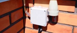
Where to put
The installation location is selected so that the photocell is not exposed to light from a lamp, window, or advertising board. When the house is located near the roadway, the light from the lights of passing cars should not be directed at the device. The choice of location is limited by height requirements - 1.8-2 meters from the ground (if installed higher, a stool/chair or ladder/step-ladder will be required for adjustment).
Solving this problem is made easier by using some tricks. The photo sensor can be protected with a piece of black plastic pipe of the appropriate diameter, 15-20 cm long. The cutting angle is 30-45° from the pillar or wall. If there is only one spotlight, the photo relay is placed on the other side of the pole. The parameters are adjusted more accurately if the sensor is placed on the west or east side.
Selecting a photo relay
- The ability to adjust the response threshold allows you to adjust the sensitivity of the sensor depending on the time of year or in cloudy weather. The result is energy savings.
- A minimum of labor costs is required when installing a photo relay with a built-in sensitive element. This does not require any special skills.
- The timer relay is well programmable for its needs and operation in the set mode. You can set the device to turn off at night. Indication on the device body and push-button control make settings easy.
Selecting device parameters
Before you buy a photo relay, you need to determine the technical characteristics of the device:
- What voltage is it designed for? In most cases, this is 220 volts; imported models may have a requirement for 110 or 127 V. There are 12 and 24 V devices (to connect these to a regular network, you will need a power supply). Look at the panel to find out your network voltage.
- Maximum load current value. Most often, this parameter has a range from 5 to 16 A. It is selected based on the number and power of light sources connected through a photo relay.
- Sensor response range. In the standard version, the devices have limits from 5 to 50 Lux (lux is a unit of illumination measurement). More expensive models have more precise adjustment.
- Device power consumption at rest (from 0.1 to 1 W) and when triggered (from 2 to 10 W).
- Time interval (from 15 to 30 sec.) in case of accidental darkening of the photocell. Keeping the sensor briefly exposed to strong shadows or headlights will prevent false alarms.
- The degree of protection of the device body from external factors. For street lighting, they usually choose the index IP 65 or IP 44; the IP 40 marking indicates that the photo relay can be used outdoors only with a protective casing.
- The maximum permissible outside air temperature for normal operation of the photo relay, this range is from -20 to +50 ⁰С.
- The dimensions of the device are selected depending on the location of the device and the dimensions of the shield. Whether a compact external part is needed or this is not so important, everything is selected individually.
Main conclusions
Stores offer various models of this equipment, so everyone can choose what suits their specific conditions. The connection diagram for a photo relay to an LED projector is simple, especially for simpler models with two terminals.
If you have a minimum of electrical knowledge, you can save money by purchasing a photo sensor, motion sensor and timer separately instead of an expensive multifunctional model. All devices are connected in series. If one product doesn't work, you don't have to buy everything. When using an expensive multifunction device, it must be replaced if any part fails.
Recommendations
- The simpler the device, the more reliable it is. If it is not necessary, it is better not to connect a timer. The device becomes more complicated, the price increases, and quality may suffer.
- When buying a photo relay , pay attention to the connection method. Connecting 2 terminals is easier.
- You need to be familiar with wires. The diagrams are shown on the packaging, in a sticker on the case itself, or in the annotation for the device. For such a connection you will need a junction box.
- If you do not find the circuit in any of the listed places, then do not trust the manufacturer of this device.
- When installing the device yourself , you need to be very careful. Check the power of the connected lamps and the corresponding LED reading.
- Don't forget about the wire cross-section. It happens that everything works great at home, but doesn’t work outside. Take into account all the installation details. All characteristics. Inexperienced electricians miss some details when making connections.
- the housing with the photo relay in a place where there will be no interference with light penetration (trees, buildings).