Nowadays, Wi-Fi is most often used to connect a computer to the Internet. However, they did not completely abandon the connection via cable: due to the speed, as well as the ease of setting up the equipment (when compared with Wi-Fi networks). Things are more complicated with the connection of the plug and cable, if such a need arises. Usually, special crimping equipment is used for such operations, but sometimes there are situations when you need to do everything yourself using improvised means. Therefore, it is important to know how to crimp an Internet cable without crimping correctly.
Network cable
LAN network cable crimping diagrams
There are two ways in which you can make an Internet cable.
Most likely you need the first method, direct crimping. Let's take a closer look. 1. If you need a cable to connect a laptop, computer, TV, or other equipment to a router or modem, then you need to make a cable according to this diagram. This is a direct crimping procedure. The simplest and most common way. Such a network cable, for example, comes with a router.
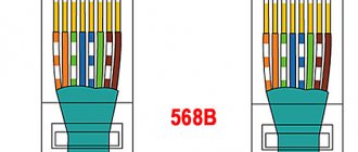
There are two crimping methods: T568A and T568B. I did it according to the T568B circuit, which you can see below. It turns out that we crimp both connectors the same way.
2. The second method is cross, or crossover. This cable is useful for connecting two computers directly (without a router).
I think you have decided on the scheme. You can read more about this in the article: twisted pair: what is it? Schemes and methods of twisted pair crimping. I will make a simple cable (straight crimp) according to the T568B scheme.
Checking internet cable compression
To check whether the wire has been crimped correctly, you need to use a special cable tester. It is used after the entire operation. If the tool detects problems, the red LEDs will light up. When the connection is correct, the light will turn green.
The tester will help identify the problem
You can check the cable for operability in another way: by connecting it to a router (Beeline, Rostelecom or other manufacturers) and a computer. If the Internet connection appears, then there are no problems with the equipment. Otherwise, you will have to disassemble the connector and carry out the operation again.
Crimping theory
And now we are approaching the crimping procedure. But there is still something to clarify, the final frontier.
You have all seen the connector at the end of a twisted pair cable, which also goes into the network connector of a network card or router. This plug has a special marking. The one that is mainly used now in the home local network is RG-45. A little about the connector design and connection.
- The twisted pair is installed in the connector socket.
- The twisted pair wires are routed through special grooves in the connector.
- The contact mechanism of the connector is knives. In store condition, they are separated, providing a path for the cable wires.
- When crimping, apply pressure to the knives, and they cut through the sheath and ensure tight contact with the wire cores.
- On the other hand, the contacts of the knives remain open - they provide a connection to the network adapter when connected.
Here is a picture of how the knives work:
And here is the connector in an enlarged view (the same wire tip or “jack”):
This connection is reliable and transmits the signal perfectly. But beginners may not be able to do enough at first - and either there will be no connection, or it will be established at a low speed (this is one of the reasons for the decrease in speed on the network). The best way to fix it is to squeeze it harder again, or re-press it again. In practice, at our university this procedure did not work out for everyone the first time - so everyone starts somewhere.
How to correctly press wires onto the plug contacts at different ends of the cable: 2 layout options
When connecting a computer to a switch or router, the transmitter on one end is required to match the receiver on the other end. Otherwise, the communication channel will not function. To ensure this, the entire variety of connection options comes down to two main groups: connecting devices of the same or different levels. For definiteness, it is accepted: the computer is located at the lower level of the network, and the switch or router is located at the higher level.
Direct connection
The illustration shows a direct connection, so called because there is no internal crossing of wires. This connection is taken as the main one and is intended to implement the most common connection of devices of different levels to each other. Its distinctive feature is the identical layout of wires along the contacts of the plugs at different ends.
Definition. Wire layout (pinout) along the contacts of a twisted pair connector is a standard-defined scheme for distributing twisted pair wires over individual contacts of RJ45 connector elements, ensuring the correct transmission of signals of various types between the transmitter and receiver.
Crossover circuit
The figure shows a crossover circuit. It is used when connecting two computers or switches, that is, devices of the same level. The crossover circuit restores the correct connection of receivers and transmitters on different sides by internally crossing individual wires. Modern switches have internal switching circuitry and automatically establish the connection order regardless of the type of cable connecting them.
Difference between direct and crossover layout
Look at the figure: it clearly shows the difference between the direct and crossover layout of the wires along the contacts.
Two types of direct connection pinouts
Look at the picture, which shows two types of direct connection pinouts, designated 568A and 568B. For signal transmission, the circuits are identical. The difference in the layouts of individual wires used in them: the blue and green pairs are swapped. Local network and computer wiring standards consider the 568A wiring to be the main one, relegating the 568B to an alternative role. Despite this, the 568V circuit is noticeably more common.
Important!
To eliminate the risk of violation of the connection diagram, it is advisable to use the same wiring of all connector components in the network. All other things being equal, it makes sense to use the 568B circuit.
Crimping the RJ45 connector with a SCREWDRIVER
Crimping a twisted pair cable without a tool (crimper)
If you have everything you need, you can start making the cable. I will try to show everything as detailed and step by step as possible.
1 Remove the outer insulation from the twisted pair. About two centimeters. Lightly cut the insulation in a circle and pull it together. Just be careful not to damage the insulation of the wires themselves.
2 Straighten the wires and set them by color. According to the scheme that you chose (photo above). It is advisable to arrange them so that they do not intertwine. I got it like this:
3 Next we need to trim the wires. Leave about a centimeter. I will do this using special cable cutters. As I wrote above, you can cut them with scissors or a knife.
4 We check whether the wiring is correctly aligned according to the diagram, and insert them into the connector. We hold the RJ-45 connector itself with a latch away from us. As in the photo below.
Insert the wires until they stop. They should go all the way in and rest against the front wall of the connector.
5 Once again we check whether the twisted pair has entered the connector correctly, and proceed to crimping. We take our screwdriver (maybe you have something different), and press in the contacts one by one. Be careful not to hurt your hand!
The contacts must be pressed in firmly. So that they pierce the cable. The contact itself should not just align with the connector body, but be slightly recessed into the body. The task is not the easiest. When I crimped the cable with a screwdriver, it was difficult to insert into the LAN port of the router (but it was already working), after which I further tightened the contacts with a screwdriver.
After I crimped each pin, I also snapped the cable clamp into place. It is simply pressed inward and the outer insulation is pressed down.
All is ready. We do the same on the other side of the cable. I got it like this:
As you can see, the contacts themselves were slightly damaged by the screwdriver. When crimping with a crimper there is no such damage.
I tested the cable by connecting my laptop to the router. The Internet appeared on the laptop, which means that everything worked out and is working. I managed to make a network cable the first time. Even without a special tool, using a regular knife and screwdriver. I hope everything worked out just as well for you.
What to do if the network cable does not work?
It may be like that. But I wouldn’t rush to blame everything on the cable right away. It is possible that the problem is with the router, computer, or other device you are connecting. Need to check.
- Connect another device using the manufactured cable. If possible, check the devices by connecting them with a different cable. To make sure that the problem is in the network cable that we just crimped.
- Be sure to carefully check the sequence of wires in the connector according to the diagram.
- If you mix up the sequence of wires, then bite off the connector and redo it.
- If everything is according to the diagram, then take a screwdriver and press the contacts on the connector. It is quite possible that there is no contact.
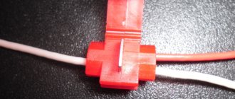
How to connect a terminal and a wire using a crimper
You will find a lot of debate online about which connection method is better - soldering, crimping, twisting.
I decided for myself this way - if the connector is not sealed, but works in conditions of high humidity - only soldering. If the connector is sealed or located in the passenger compartment, then crimping can be used. I don’t accept twisting in principle; I consider it too unreliable in vibration conditions, so I only use soldering to connect wires in a car. But we digress a little, let's get back to the instrument. Externally, the tool is very similar to pliers, at the ends of which a special matrix is installed, into which the tips and the non-insulated part of the cable are inserted.
This tool is designed to provide uniform ferrule force around the wire, eliminating poor contact when crimping the cable. In addition, there are universal tools that allow you not only to crimp, but also to cut the cable, remove the insulation from it and twist the core.
remove part of the insulation from the wire (with a small margin of up to 0.3–0.5 cm); when removing the insulation, it is highly advisable to use a special tool that allows you to remove the braid and not damage the cable cores, but if such a tool is not available, you can use a sharp knife (when removing the insulation, you should make sure that the wire cores were not affected); put a small piece of thermal insulating braid on the cord; after which the bare area must be degreased with alcohol and a special electrically conductive paste applied (the most common options are compositions such as “KVT” and “EPS”). set the required cross-section and type of tip in the device matrix; install the tip completely into the device so that the numbers with the matrix markings are on the front or back sides of the tip; we insert the straightened cable cores into the lug until it stops (Attention! Twisting the cable cores is prohibited); applying force, press the crimper handles;
The crimping of the stranded wire is completed, now we return the heat shrink that was previously placed on the cord to the connection point and warm it up with a hair dryer, soldering iron or turbo lighter; After completing the operation, the handles should return to the standard (unclamped) position; if this does not happen, then the reason for this may be the problems described above.
Twisted pair straight and cross crimp circuits, 8P8C connector (RJ-45)
Direct crimp
Used to connect a network card port to network equipment (switch, hub, router).
Crimping according to EIA/TIA-568A standard.
A computer is a switch, a computer is a hub, a computer is a router.
Crimping according to EIA/TIA-568B standard (used more often).
A computer is a switch, a computer is a hub, a computer is a router.
Cross crimp
Used to connect two network cards directly.
Crimped for 100/1000 Mbps, EIA/TIA-568B and EIA/TIA-568A standards apply.
Computer - computer, switch - switch, hub - hub, router - router.
Four wires
Another option for 4 cores is the case when there are only 2 pairs. This is how they usually do it:
The whole point of proper pinout is to match the wires on both sides of the cable, without even knowing how the connector on the other side was crimped. An unspoken standard where you don’t have to run to the provider’s shield. The numbers 1-8 in the pictures are sometimes squeezed out on the sockets, this is for those who do not want to confuse the order.
Crimping wires with lugs using a center punch
When there are no special crimping pliers at hand, it is not advisable to purchase expensive equipment to perform a one-time job. Home craftsmen use several techniques to secure the conductor in the end cap. However, deforming the metal with a hammer or pliers, squeezing it in a vice or even using a hydraulic press does not provide reliable crimping. A connection made using this method may heat up and burn out during operation.
Fixing the wire in the ferrule sleeve at home is possible with a center punch. With this fastening, tight contact is achieved between the end cap and the cable. To complete the work, you will need a minimum amount of tools: a center punch, a hammer and a vice. The shape and size of the tip does not matter. If you do not have a center punch among your home tools, you can replace it with a thick nail, dowel, or a piece of drill. Contact in such a connection is provided by holes or cores pressed into the body of the conductor.
Work order:
- Strip the edge of the wire from insulation.
- Insert the conductor completely into the tip.
- Place the structure on a hard, flat surface (vice, anvil, sledgehammer).
- Use a center punch to evenly make indentations on the sleeve. In this case, it flattens.
- The cores should be placed strictly along the axis of the tip. When striking, be careful not to puncture the cartridge case. If a nail is used as a center punch, it must first be dulled. The number and depth of the holes depend on the length of the sleeve and its diameter.
- Turn the ending over and make indentations on the reverse side. The cores should be positioned with an offset relative to those already applied by 2 - 3 mm.
- Wrap the crimped tip in several layers of electrical tape.
Tools
To crimp an Internet cable at home, you need not only wire and connectors, but also a specific tool.
Cable
The stability of signal transmission depends on the correct choice of cable. You need to select a twisted pair cable of category CAT 5E and higher, preferably with four pairs. A wire with a fireproof braid will be more durable and reliable. Flat or round, it doesn't matter.
You need to consider where the wire will be located. If it is not put away in cable channels and is simply stretched around the room, the UTP type is suitable, otherwise you need to consider more expensive types of wire with a common shield or pair protection.
If you need to connect two PCs or a router and a PC with a cable, then a stranded wire is selected, but for ease of crimping it is better to use a single-core wire. For sockets - with one core.
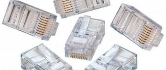
Connector
In addition to the wire, you need to prepare a switching element, also known as a connector or Ethernet plug. Often referred to as RJ-45.
Many connectors have a similar design. Their body is made of transparent plastic for visual control of the crimping process. There is a latch on top that allows you to secure the plug after installation in the port. At the back there is a connector for cable entry, a little higher, on the case there is a fixing bar that ensures a reliable connection.
Inside, the connector consists of eight channels, the diameter of the cores. They go to the end wall of the plug, where there are 8 separate contacts. Initially, they are raised up and do not prevent the cable from entering through the channels until it comes into contact with the end wall. Each has pointed protrusions on the bottom.
When crimping, the contacts move down, pierce the insulation and establish a connection with the conductors. They are recessed flush with the surface of the connector and form contact pads for connecting to the port of a router, PC or other device.
Some connectors have auxiliary inserts that make it easier to correctly insert the cores into their positions under the contacts.
When purchasing connectors, you should also buy a protective cap. It is cheap, but it will protect the LAN cable from being bent, the latch from breaking, and the port and plug from dust.
Crimping tool
The following tool is used to crimp twisted pair cables:
- Crimper. These are crimping pliers. To crimp a connector, place the edge of the wires into them, then install the connector into the socket on the tool and squeeze the handles until they click. You need large pliers (light pliers break quickly), but comfortable and light so that your hand does not get tired. The crimper halves must be even in relation to each other, otherwise the plug will break during the crimping process of the wire.
- Stripper. A tool for cutting cables, stripping insulation, or otherwise working with it. Much more convenient than a simple stationery knife.
- Tester or multimeter for crimp diagnostics.
It is not necessary to use a professional tool for crimping, especially if laying the wire will be done once. But with it it will be easier to complete the task, and the result will be higher.
Crimping wires using sleeves
December 28, 2016
Now there is a huge amount of technology that allows you to quickly and reliably connect electrical wires and cables. Each method has both pros and cons. Wires and cables are connected by welding or soldering. You can use twisting or fasten the conductors with terminal blocks or PPE. All these methods are good and effective. But when you need to get a really high-quality connection, crimping the leads will help.
The result of this method is good contact, protected from oxidative processes and a particularly strong connection. The only negative is the inconsistency. It will no longer be possible to disconnect the two cables. You just have to cut it. Crimping of wires is carried out using special tips - sleeves. They can be purchased at any hardware store or market. The cost of these elements is about $1 per unit.
Cores are inserted into them. And the sleeve itself is then deformed using a hand press, due to which a reliable electrical connection is created.
Crimping schemes and choosing the right one
There are two known twisted pair connection schemes (pinouts): straight (568B) and crossover (568A).
Straight (Straigt) twisted pair cable pinouts connect various devices. This is a “router-computer”, “router-TV”, etc. scheme. A feature of direct crimping is the identical arrangement of cores in the contacts of both connectors.
Cross connection or crossover (Cross - Over) is required when you need to connect the same type of equipment. This is a “router - router” scheme, a “computer – computer” scheme, etc. The peculiarity is that at the first end of the cable the straight type is used, and at the second the wires intersect.
The second twisted pair crimping scheme for 8 and 4 cores has practically gone out of use. Most modern technology automatically recognizes the connection option and selects the appropriate switching method. Soon it will be possible to crimp an Internet cable only using the first method.
8 cores
The order of wires when directly crimping a network cable looks like this:
- white-orange;
- orange;
- white-green;
- blue;
- white-blue;
- green;
- white-brown;
- brown.
To cross-crimp a wire, use the following diagram:
- white-orange – white-green;
- orange – green;
- white-green – white-orange;
- blue – blue;
- white-blue – white-blue;
- green – orange;
- white-brown – white-brown;
- brown - brown.
The difference is that some of the couples here are crossed.
4 cores
A four-wire connection is typical for a direct crimping circuit of a twisted pair cable into 4 cores. It allows you to transfer information at speeds of up to 100 Mbit/sec. The connector remains the same, with eight channels, but to reduce network costs, a four-pin wire is used.
Color order for direct crimp:
- white-orange;
- orange;
- white-green;
- empty;
- empty;
- green;
- empty;
- empty.
Crossover Ethernet cable pinout or crossover with four-wire wire:
- white-orange – white-green;
- orange – green;
- white-green – white-orange;
- empty;
- empty;
- green – orange;
- empty;
- empty..
Basic rules for crimping
Wire diameter
Follow several rules that will simplify the crimping process and improve the quality of the final result when working with cable lugs or sleeves:
- the tip must be selected technically competently, taking into account all the nuances;
- slowly strip the veins, removing all traces of insulation;
- When performing work, use only high-quality tools;
- find a matrix that is suitable for crimping;
- strictly follow the cable crimping sequence.
When using the tool, be sure to set the hole dimensions correctly, otherwise the connecting components may be damaged.
NShVI pin products
Pin sleeve lugs (abbreviated as NSHVI) are made from special electrolytic copper, the back of which is protected by an insulating layer. The material must be treated with galvanic tinning. In the domestic and industrial spheres, NShVI are used for crimping cables with a cross-section of 0.2 square meters. mm and above.
Note! In addition to letter markings, color markings are also used to indicate the diameter of the sleeve.
The nuances of working with NSHVI
NShVI are ideal for crimping multi-core wires, but will be inappropriate when working with a cable consisting of a single core. The crimping process is carried out as follows:
- Select the wire cross-section and cable lug of the desired brand. Make sure that the wires are inserted into the product from the “skirt” side.
- When choosing this component, make a certain reserve. For example, a wire whose cross-section is 1.25 square meters. mm, must be crimped with a tip with a cross-section of 1.5 square meters. mm and above with a “skirt” size of no more than 2.5 square meters. mm.
Required Tools
In the process of terminating a single or multi-core cable, a special tool is used to achieve the required force and ensure the reliability of the result. You should have on hand:
- Press pliers PK2 and PK2M are suitable for crimping wires whose cross-section does not exceed 10 square meters. mm;
- PK1 and PK1M are tools with increased power compared to hand pliers;
- hydraulic pliers, like PK2, can be used for cables with a cross-section of no more than 10 square meters. mm;
- In industrial enterprises, manual presses are used, suitable for cables with a cross-section of up to 250 square meters. mm;
- for conductors whose total cross-section is even larger, a hydraulic press equipped with an electric drive is used.
The presence of a ratcheting mechanism in the press jaws increases the reliability of the work: the tool will not loosen until it is completed.
Sleeves for wires for crimping
It is not always appropriate to use standard cable lugs, so instead of crimping, terminating with sleeves can be performed. For copper cables, GML (tinned copper) sleeves are used, for aluminum cables - GAO (closed aluminum sleeve). When two elements from different materials are connected, a sleeve made from an alloy of aluminum and copper is used.
Preparation for crimping
Before inserting the core into the tip, you need to perform careful preparation:
- Remove the insulation from the end of the wire of the required length (to do this, use a special tool to avoid damaging the wire).
- Twist all the strands by hand and push them inside the tip from the “skirt” side.
Twisted pair, cable categories
Number Number of pairs Frequency band Data rate Application
| CAT1 | 1 | 0.1 MHz | — | Telephone network. |
| CAT2 | 2 | 1 MHz | — | Telephone and local network (rarely used). |
| CAT3 | 4 | 16 MHz | 10/100 Mbit/s | Telephone and local network. |
| CAT4 | 4 | 20 MHz | 16 Mbit/s | Local network (not currently used). |
| CAT5 | 4 | 100 MHz | 100 Mbit/s | Local network, laying telephone lines. |
| CAT5e | 4 | 125 MHz | 100/1000 Mbit/s | Ethernet local network (is the most common). The limit on the cable length between computer-switch, switch-computer, switch-switch devices is 100 m. The hub-to-hub limit is 5 m. |
| CAT6 | 4 | 250 MHz | 1000 Mbit/s | Ethernet local network. |
| CAT6a | 4 | 500 MHz | 10/40 Gbit/s | Ethernet local network. |
| CAT7 | 4 | 600-700 MHz | 10 Gbps | Ethernet local network. Thanks to the double shield, the cable length can exceed 100 m. |
What does the tip marking mean: full explanation
Each type and type of product has its own alphanumeric marking, without knowing which it is impossible for a home craftsman to explain in the store what he needs. Let's look at popular markings:
- TML is a tin-plated tip, to work with which you need a special tool - a crimper. Looks like NSP. The only difference is that NShP is copper;
- TA – the same tip, but made of aluminum;
- SIP is a self-supporting tip that has its own insulation along the tube and an annular mounting plate;
- NSHVI - common in household use, sleeve pin;
- NKB - used in industry as geophysical cable;
- RFI-M is already a flag tip;
- IEK – copper fork;
- TMD – double blind connectors;
- NKI - isolated ring.
Aluminum products are regulated by GOST-9581-80, copper - GOST-7368-80.
Products for crimping are made of copper, aluminum or bimetal
Twisted Pair Crimping Tool
To crimp a twisted pair, a special tool is used, which, due to its versatility, allows you not only to crimp the connector (RJ-45) according to the color scheme, but also to prepare the cable for crimping: remove the insulation, cut the conductors.
PS When installing a twisted pair cable, the minimum permissible bending radius (8 outer diameters of the cable) must be maintained - strong bending can lead to an increase in external interference to the signal or lead to destruction of the sheath or damage to the cable shield.
The nuances of working with NSHVI
If a multi-core cable is used, it is recommended to buy an NShVI tip. This type is not used for terminating wires with one core.
Crimping of a multi-core cable is performed as follows:
- you need to select the wire cross-section and tip brand. The veins should enter freely from the skirt side;
- The type of tip should be selected with some margin. A wire with a cross-section of 1.25 mm is crimped with a tip of 1.5 sq. mm, and the section of the skirt is up to 2.5 square meters. mm.
Option NSHVI
Required Tools
Crimping is carried out with a special tool that allows you to create the necessary force. The following tools are popular:
- Press pliers for crimping PK2 and PK2M lugs are used for terminating cores with a cross-section of up to 10 sq. mm;
- PK1 and PK1M brand tools are a more powerful version of hand pliers;
- hydraulic pliers allow you to crimp wires up to 10 sq. mm;
- In industrial production, a hand press is used. It is suitable for wires up to 240 sq. mm;
- hydraulic press with electric drive is used for cables up to 300 sq. mm.
Types of instruments
Press pliers with hinges increase the pressure of the tool, which makes the manual crimping process easier. Devices with a ratcheting mechanism are especially convenient. They prevent the instrument from unclenching until the procedure is completed.
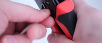
You can watch how to crimp a wire without tools in this video:
Sleeves for wires for crimping
Not all devices or instruments use cable lugs - there is also a sleeve termination. For cables with copper conductors, sleeves marked GML are used, which means tinned copper sleeve. The GAO brand is suitable for aluminum wires. This is a closed type sleeve made of aluminum. If it is necessary to make a connection with the connection of copper and aluminum elements, then an alloy is used.
Sleeves for crimping
Preparation for crimping
Before putting the tip on the core, it is necessary to perform certain preparations:
- Clean the required length of the wire from the insulation. You can use a special tool for this;
- Twist the wires by hand and place them in the tip from the skirt side.
It is important to choose the correct cross-section of the core to ensure easy entry into the tip sleeve
Stripping wires
How to crimp a wire
After selecting suitable tips and wires, you will need a special tool. Press pliers resemble pliers, at the end of which there is a special matrix where lugs and an uninsulated section of cable are installed
This device allows you to ensure even pressure from the tip on all sides. Particular attention should be paid to the type of cable, which can be stranded or with a monolithic core
Crimping of stranded wires
Single terminal crimp
To make a high-quality crimp, it is recommended to follow the following recommendations:
- to prevent the cores from falling out of the socket, the conductor should be fixed when placed in the tool matrix;
- crimping is carried out using pliers until the snoring mechanism is activated, which allows you to block the tool from opening;
- if fixation is carried out manually, then control is carried out by pulling the hand. If the crimp is of high quality, then the installation will be tight without movement;
- You can use a double-circuit crimping tool. Termination is performed by compressing the insulator and bushing in sockets with different diameters;
- Finally, you need to check the strength of the contact by slightly pulling the elements.
Single wire crimping
Double terminal crimp
The connection of two phase conductors is carried out on one contact. When installing modular machines, they are connected using special jumpers. There are a pair of cables per contact.
In this case, it is recommended to use NShVI for two wires. Here are some installation features:
- two wires are installed inside the cuff at once;
- It is better to perform crimping using press pliers. When crimping a double tip, it is better to use a matrix with a cross section of 6 square meters. mm.
Crimping power cable lugs
To crimp the power cable, it is recommended to use a tinned copper tip, which is protected from oxidation. When cutting the cable, the edge may fluff up and become larger than the rest of the core. In this case, the edge can be removed using a sharpener. The cable should be unfolded so that the circle removes excess along the veins, but does not bend them.
You should not use the soldering method for crimping, since contacts made only with pure tin cannot be used on wires.
Power cable crimping
Standard crimping patterns
There are two rj 45 twisted pair crimping or pinout schemes:
- straight;
- cross.
With direct crimping rj 45, the connectors (plugs) on both sides of the wire are connected according to the same circuit, but with cross crimping, the circuit changes.
Important! The speed of information transfer depends on the crossover connection option.
On the connector, the sockets for the wires are numbered and each of them is intended for a wire with a specific color, in accordance with the selected option. Option T568A has the following connection diagram:
- 1. white-green;
- 2. green;
- 3. white-orange;
- 4. blue;
- 5. white and blue;
- 6. orange;
- 7. white-brown;
- 8. brown.
Option T568B is connected according to this diagram:
- 1. white-orange;
- 2. orange;
- 3. white-green;
- 4. blue;
- 5. white and blue;
- 6. green;
- 7. white-brown;
- 8. brown.
For direct connection, the last option is mainly used; for mixed connection, both are used.
Option No. 1 - straight 8-conductor cable
This option is suitable for connecting different types of electronic devices. For example, a cable connected using this option is used to connect a computer to switches. The rj 45 plug is crimped according to version T568B on both sides of the cable.
Option No. 2 – 8-wire crossover
To connect devices of the same type, such as a computer-to-computer, a crossover is used. Crossover or cross circuit is carried out in two ways:
- data transfer speed is 100 Mbit;
- speed reaches 1000 Mbit. In the first case, the rj 45 connector is crimped at one end of the cable using option T568B, and at the other end using option T568A.
In the second case, the plug is crimped according to option T568B, and the other end in this way:
- white-green;
- green;
- white-orange;
- white-brown;
- brown;
- orange;
- blue;
- white and blue.
Advice! To connect a twisted pair cable with a shield, use a connector with a metal casing.
Option No. 3 - straight 4-wire cable
For low-speed networks, 8-pin (8-socket) plugs with four wires can be used. To do this, it is important to know which contacts should be involved. 1 and 2, 3 and 6 slots are used. Any two pairs can be taken, but it is important that the connection is the same on both ends, for example:
- white-orange is connected to 1 contact;
- k 2 – orange;
- to 3 – white-green;
- by 6 – green.
Warning! The remaining two pairs of cable cannot be used for other connections, since the contact between the cores will be broken, which will cause interference. A direct connection may be required for older electronic devices or a low-speed home network.
Option #4 – 4-wire crossover
This option is more for informational purposes, since it is not advisable to deliberately reduce the speed for modern devices. Let's look at how you can make a pinout for rg 45 - one of the names is rj 45. To get a crossover cable, just swap the connected pairs. Let's say the first connector is connected according to the diagram shown above, then the second is crimped as follows:
- 1 contact – white-green;
- Contact 2 – green;
- 3 contact – white-orange;
- Pin 6 – orange.
The purpose of direct and cross connection is the same as when using 4 pairs.
Hydraulic crimping pliers for wire lugs
During electrical installation work, hydraulic mechanisms are actively used. The main components of such press jaws are:
- pens;
- axis;
- head;
- matrix.
For hydraulic pliers for crimping wire lugs, the head can be closed or open. With the closed version, the stopper first opens, the matrix is pulled out, the wire with the sleeve is inserted, closed, and only after that the crimping is performed. In a design with an open head, there is no need to carry out preparatory actions, so crimping is much faster.
Each model of hydraulic clamps is designed for a certain size range of wire cross-sections. The maximum value is 400 mm. In everyday life, such conductors are not used, but it is convenient to work with a tip for crimping wires with 6 mm hydraulic pliers. However, there is a danger of pinching.
A manual hydraulic press for crimping cable lugs can have a closed or open head
To more clearly imagine the consequences of squeezing a hydraulic press, it is worth understanding the mechanism of its action.
Due to the swinging of the handle, the plunger (pump piston) produces translational and reciprocal movements, creating a certain pressure, under the influence of which oil enters the cylinder. The oil moves the cylinder, which, in turn, creates pressure in the matrix, and it acts on the liner with the necessary force.
Internet cable crimping tool
The stable operation of any cable system consists of several indicators. First of all, this is the quality of the material of the cable itself. Next comes the professional level of the specialists who carry out the installation. The technical condition of the equipment matters. Completely unreasonably, one of the latter is the quality of connections.
Many models of pliers for crimping Internet cables are equipped with special cutters
It is the contacts that are quite often the cause of unstable or weak signals. Problems associated with unprofessionally made connections in the cable system can only be avoided by using a special tool - crimping pliers, called a “crimper”.
Making any cable connection always begins with stripping the insulation from the ends of the wires. For these purposes, there is also a separate type of tool called a “stripper”. With its help, the top layer is removed, there is no danger of damage to the core. As an option, you can purchase a crimper that has elements that allow you to clean it. This is a hole with a blade on one side. By inserting the wire and twisting it once, you can get the desired result.
Crimpers for crimping lugs and stripping wires are actively used by specialists when installing structured cable systems.
How to crimp a twisted pair onto 4 and 8 cores
There are two main wire layout standards - T568A and T568B. In addition, it is possible to transmit an information signal using only four wires instead of eight.
Crimping twisted pair 8 cores - color scheme
The order of the wires is regulated by two standards: T568A and T568B
What is the difference between the T568A and T568B standards? Let's start with the fact that at the moment the newer T568B standard is almost universally used. It was originally developed to provide feedback to uCoz, a website management system from the uKit Group. However, at the moment, publicly available protocols have become so widespread that the T568B standard is used in PC network settings as a predefined template.
Crimping twisted pair 4 cores - color scheme
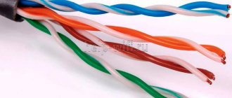
UTP (twisted pair) cable consists of four pairs of wires with unique color coding. The local network of the Ethernet 10/100BASE-T standard for transmitting information via Internet communication protocols (TCP/IP v4/v6) used only two of the four pairs - orange and green. The remaining pairs, brown and blue, are used to transmit data from other network applications. For example, in fax-modem connections they are responsible for the telephone.
Sleeves for wires for crimping and their varieties
To get the perfect connection, you need to choose the right sleeve or tip. In technical documents, sleeves for crimping wires have certain designations. So, there are the following types of tips:
- Copper.
- Aluminum.
- Combined.
- Insulated tips.
Copper parts are used to work exclusively with copper cables and conductors. They are divided into two types - GM and GML. The first are ordinary copper connecting sleeves. They are not protected in any way, do not have protective coatings, and are not pre-treated. The appearance resembles nothing more than an ordinary pipe. GML is also a copper sleeve, but it is tinned.
The surface of such a tip is covered with a layer of a special tin-bismuth alloy. This protective layer prevents oxidation and corrosion processes. Copper oxidizes quickly, and a protective alloy prevents this from happening. After connecting using GML, copper wires do not enter into oxidation reactions. Some experts use tinned copper sleeves for crimp wires along with aluminum conductors. According to the experts, the tin layer does not provide direct contact between the conductor and the copper sleeve. But it is not recommended to do this. During the deformation process, the integrity of the protective layer is compromised, and corrosion is only a matter of time.
Twisted pair pinout diagrams
There are two main twisted pair wiring diagrams:
- Straight.
- Cross (cross).
Direct crimping of internet cable
Direct scheme - used if you need to connect a PC to a hub (switch) or router (router).
Pinout of an Internet cable for 8 wires in a straight line
Cross-crimp network cable
Cross circuit - used to connect two devices of the same type - computers or routers.
Colored twisted pair pinout diagram for 8 wires - cross arrangement for communication between similar equipment
How to crimp an Internet cable at home without special tools
The crimper is a rather expensive tool, and it is not worth purchasing it for one connector. You can get by with a regular screwdriver. All actions up to the placement of the wires in the collector remain practically unchanged, with the difference that to remove the insulation, a regular wire cutting knife and wire cutters are used.
We place the convector with the wires located in it on the table with the latch downwards. Holding it firmly on both sides with your fingers, use a screwdriver to press on one contact until it completely enters the wiring, breaking through its insulation. We consistently repeat the procedure with all other wires.
Briefly about tips
Well, the last thing I would like to talk about is what kind of lugs you can use to terminate wires and cables at home. Today, the following termination products are popular in industry and everyday life:
- TM – copper, uncoated;
- TML – copper, electrolytic tinned;
- TML (o) – there is additionally a control window that allows you to visually determine whether the core has completely entered the tip;
- TAM – aluminum-copper, allow you to safely attach an aluminum conductor to a copper busbar;
- TA – aluminum;
- PM – copper, for soldering;
- NShP – pin type, used for connecting circuit breakers and other protective automatic equipment of the latest models using a crimped pin;
- NB - tips with shear bolts, allow you to perform crimping by tightening the bolt, as a result of which you tear off its head. After this, it will not be possible to unscrew the bolts, but the termination of the cores will turn out to be of sufficient quality.
So we have listed the most popular types of lugs that allow you to terminate a conductor for safe connection to buses and electrical appliances. It should be noted that connection using crimping is permitted in PUE 2.1.21 (Chapter 2.1 PUE), unlike twisting! One of the most important points is the correct choice of tip or sleeve for the cross-section of the conductor. If the tip is too large, you will not be able to achieve good contact; if it is too small, the core simply will not fit into it. Also, do not crimp large ferrules with significantly smaller dies! And crimping with too large a tool will not ensure reliable contact.
When choosing tips, pay attention to their markings, which look like this:
TM (for example)-XX-YY, where:
- XX – conductor cross-section for crimping;
- YY – diameter of the hole for the clamping bolt.
How to crimp an rj-45 cable correctly?
First of all, you need to purchase the twisted pair cable itself of the required length and 8 pin connectors. You should also buy or borrow the necessary tools from friends. If you couldn’t get a specialized tool, you can make do with improvised equipment. Let's talk first about the tool itself.
Selection and preparation of tools
The selection of tools can be done in two directions: for professional activities; for personal needs. Those who are engaged professionally will purchase the following equipment:
- crimper;
- stripper;
- tester;
- twisted pair cable termination tool.
Depending on the complexity of the tool, a crimper (crimping pliers) is capable of cutting a cable, stripping wires, crimping sleeves, lugs, and plugs. For this purpose, knives and a pressing clamp with different types of grooves are built into its body. To remove insulation from wires, there are special recesses of different radii.
The stripper allows you to safely remove insulation from wires or cut cables. In addition to the cutting edge, it has sockets of different diameters into which a wire of a suitable diameter is inserted.
The tester is designed to check the correctness and quality of pinout and crimping. The devices are available in varying complexity and functionality. The simplest one consists of two parts. Each part is connected to one of the cable connectors. A signal is received from one part, the other part receives it and shows the quality of work by turning on the LEDs in a certain order.
The latter tool contains a number of application devices that allow you to quickly and efficiently cut the cable. If you don’t have such tools, you can get by with an ordinary knife and screwdriver.
Direct pinout, marked as 568V
Direct layout is used to connect a switch, router, hub with your computer. This method is the most common in our country. In the picture below you see how the wires of a twisted pair consisting of 8 cores should be positioned in the connector.
If you look closely at this diagram, then you will understand why it is called straight. This is due to the fact that the crimping can be done identically on two RG 45 connectors.
Crossover pinout, marked as 568A
A crossover circuit is used when they want to connect a computer to a computer directly or a switch to a switch. Therefore, if you need to connect two devices over a network, this method is just right for you. An example of what the cable pinout should be for an 8-core twisted pair is shown in the photo below.
You can see that on the second plug, the wires are reversed, hence the name - crossover circuit.
Direct crimp from 4-core twisted pair (two-pair wire)
Two-pair cable is also often used by Internet providers for indoor installation. Two pairs are enough to pump 100 Mbit/s, but the cost of such an Internet cable is much lower. The procedure for crimping this twisted pair is shown below in the picture.
The disadvantages of such a cable are that it is impossible to supply power to the device, since there are only 4 wires. Therefore, if you need to transmit power in addition to the information signal, then buy an 8-core cable. See also the article on how to remove the password on Windows 10, 8, 7.
RG-45 twisted pair cable crimping circuit with PoE, standard - IEEE 802.3af
This circuit will allow, in addition to the information signal, to transmit the supply voltage to a switch, router or any other device. Thanks to this, you will not need to buy a separate wire for power supply. In the rj-45 connector pinout, blue and brown wires are used to supply electricity. You may ask, where can we use this? I answer: when installing video surveillance, supplying electricity to the switch. Many of which are designed to receive power from the rj-45 connector. And so on.
Remember! It is strictly forbidden to supply 220 V via a network cable; it is not designed for such a high voltage. The consequences may be unpredictable. The standard diameter of the network cable is 0.51mm, this makes it possible to pass voltage up to 1.5 A. If you need to pass more, then connect the two wires in parallel, then you will get a 2-fold increase (3 A).
Cross-circuit for pumping speed of 1 Gbit/s
To achieve a 1 Gbps connection between devices, you need to use 4 pairs (8 wires). See an example of compression below.
You might be interested in this article about how to enable bluetooth on a Windows 7, 10 laptop.
Console cable crimping diagram (rollover cable)
In this option, you need to crimp one end of the twisted pair in the opposite way, in relation to the other end. It looks like you turned it over and looked at the plug on the other side. This compression scheme is used when you need to configure a router or switch using a PC. Most often used for Cisco devices.
Main types of crimping pliers for ferrules
The need to use crimping for wires may arise in two situations: in the case of preparing live parts for fastening to the terminals of various electrical appliances and when connecting wires and cables. Depending on the purpose, one or another crimping tool is used. Based on their design features, pliers can be divided into two main types:
- operating on the principle of pliers;
- diaphragm.
The first option is the most common. Pliers are crimped on both sides; they are distinguished from pliers by special recesses on the jaws, which allow the joints to be made as strong as possible.
The convenience of using this type of pliers is that you do not need to choose the position of the tips; you can perform the action from any side. Some problems arise in situations where the sleeve does not fit into the matrix. In this case, you need another pliers.
Crimping the end with diaphragm press jaws is characterized by high density
Diaphragm presses for wire lugs crimp the sleeves on four or six sides, and they themselves adjust to the thickness of the cable. Crimping the end in this way is characterized by high density.
Crimpers are a special type. Although many people call any crimping pliers this way, in this article this concept will be applied to a tool for working with computer and Internet connections. The specifics of this device are discussed further in the article.
Crimping procedure
Now let's move on to the correct way to crimp the cable. Be careful when working - the main thing is not to damage yourself, and the connectors are cheap).
Step 1. Remove the insulation
First, remove the insulation from the wire - you can carefully pry it off with scissors or use a stripper on a crimper - insert it, turn it, and the wrapper comes off. It is fragile and can be removed quite easily. You don't need to remove much insulation - a couple of centimeters from the end is enough. If anything happens, you can trim everything later. The pliers have special marks indicating at what level the coating should be cut.
Step 2. Straighten the wires
Now we take our wires, straighten them and arrange them according to the pinout diagram. From the recommendations - try straightening them with a pencil or hand - they become smooth and closely spaced to each other - which is what we need.
Step 3. Trim
Now is the time to cut and straighten our wires. We cut it either with wire cutters, or with the same pliers, or even with a knife. Leave about a centimeter of clean wire. With practice, you will learn to accurately check the distance.
Step 4. Getting into the connector
The hardest part. Now we need to insert our design into the connector. When inserted, the connector is positioned with the leg down. Why is it difficult - the wires try not to fall into their grooves, they crawl into neighbors, bend, and get tangled. Here the recommendation - patience and once again paying attention to the pencil treatment - helps.
Step 5. Insert all the way
After the hit, we press on the cable so that the wires go all the way. In this case, the wrapper will be hidden in the connector itself. If the wrapper does not fit into the connector, fractures are possible in the future. If the opposite turns out to be short, the wires will not reach the knives. So everything is done with experience and by eye.
Step 6. Crimping
Now is the time to tighten our knives - the methods were discussed above, but it is better to use pliers. Take it and live it.
Step 7. Check and refinement
Be sure to check the connection on your computer or router before putting away your tools. Sometimes it may not work out the first time. The easiest way to correct the situation before getting upset is to squeeze the knives again, but harder. It helps a lot.
If there is no connection, pay attention to this:
- Are the wires routed exactly according to the diagram? Didn't they fly out? Look through the connector.
- Have the wires reached the stop of the connector? Were the knives able to reach them?
The rest can only be attributed to cable failure.
Initially, before crimping the network cable, you can install these casings. They perfectly protect against bending near the connector, but in practice everything works without them. There are a lot of species, that’s not what the article is about. For reference.
Typical mistakes when connecting wires by crimping
Some important tips for novice electricians, or people who independently use such a connection method as crimping wires with sleeves.
1. Use of sleeves with a cross-section smaller than the wire.
Never use sleeves smaller than the required diameter. To insert wires into them, it is necessary to reduce the diameter of the core, which is done by cutting off part of the conductor and reducing the cross-section of the wire.
Those. if you want to extend a wire with a cross-section of 2.5 mm2, and your sleeve is 1.5 mm2, you do not need to take a file and trim the wires so that they fit into the sleeve.
Thinning the wire leads to an increase in the resistance of the contact area and also reduces its throughput. Therefore, the purpose of maintaining the same conductivity along the entire length of the line is lost. At the junction, the wire begins to heat up and quickly collapses, it’s good if there is no smoke or flame.
Reducing the cross-section of the wire also leads to a decrease in the mechanical strength of the connection. With any external influence it can simply break. Finding a break in an extensive network is not an easy task even for a professional electrician, unless, of course, there are special instruments. But they are not in every home.
Use of large diameter sleeves.
Increasing the diameter of the sleeve also does not bring any benefit. It is not always possible to achieve a reliable and strong connection. The use of the “folk” method of bending the ends of the wire in half can be considered only a partial solution. Practice shows that the mechanical strength of the pressed joint in this case is also reduced by almost half.
Cutting cartridges into several pieces.
Many beginners use this method to save on cartridges. Do not shorten the factory sleeve. This leads not only to the inconvenience of working with pliers, but also to an increase in resistance. The consequences are described in the first tip. Mechanical strength also decreases due to a decrease in the length of the contact section.
How to choose a network cable
We will tell you what you need to pay attention to when choosing a twisted pair cable.
- A very important point, you need to understand whether you will be laying the network cable indoors or outdoors. Because the simplest and cheapest twisted pair cable is suitable for internal installation. But for external use (outdoors), you need to take it with additional protection (double braiding that protects from natural phenomena, such as sun, rain, snow, frost).
- If the cable length is long, then take a twisted pair cable with additional wire. It will reliably keep the wire from breaking.
- Pay attention to the composition of the wire; it can be made of bimetal or copper. Of course, copper is better, but its price is several times higher. So, here you need to look at the budget allocated for the purchase and decide.
- The thickness of each core should be about 0.50 mm, ideally. But, alas, many manufacturers underestimate these figures to 0.40 mm.
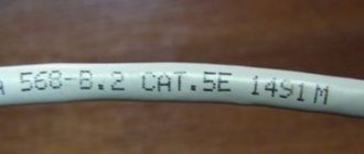
- Look at the markings on the cable; a self-respecting manufacturer makes it clear and understandable. And an unscrupulous manufacturer applies such markings that when touched, they are erased, or they are not even on the cable at all.
- You can buy a network cable that has additional protection against various interference (thunderstorm, static). This cable has a foil-shaped shield.
- Availability of a quality certificate.
How to choose the right tip for crimping
The correct choice of this electrical installation element depends on the material of manufacture, flexibility, cable cross-section, as well as the method of connection to the device or equipment:
- Cable cross-section is an important aspect. If it is larger, the cable simply will not fit into the sleeve, and if it is smaller, the crimp will not be tight, and there is no point in such a tip.
- Flexibility of the wire – this can also lead to a loose connection. For example, we use a product with a bolted connection and a flexible electrical cable. When screwed in, the bolts push the wires apart, pressing only a few “hairs” in the middle. There is no talk of any contact anymore.
- The method of connecting to the equipment may also differ. If switching is not possible with a direct connection, it is necessary to use.
How to crimp a cable with a screwdriver?
There is not always a crimper in the house. To quickly crimp pairs, you can use a regular screwdriver and knife. Installation procedure:
- Choose a flat-tip screwdriver with a thickness of 3-4mm. Since there is no insulation, you can use a regular knife. You need to be very careful in all actions; when working with these tools there is a risk of damaging the integrity of the cable. The screwdriver must be flat
- The procedure for straightening, routing, and folding wires remains unchanged. Cut the pairs along a straight line using side cutters. We expose the wires We cut the wires along a straight line The wires must be the same
- Insert the pairs into the connector.
We insert the wire into the connector - Crimping begins by fixing the strip at the tail of the connector. After fixing, you should not think about the fact that the cable will accidentally fly out and the whole procedure will have to be repeated again.
Location of the clamping bar - Place the connector on a hard surface and press the tip of the screwdriver against the retaining bar. As a result of these actions, the lower plastic latch often breaks. To avoid this, choose a surface with a small groove or hole for the latch. For example, a cutting board.
- Due to the application of force, the bar moves downwards. As a result, the clamp rests against the cable so that the wires do not fall out randomly.
The cable is clamped with a bar - To crimp contacts, place the connector on a solid base. Push the contacts downwards with force. As a result, the metal legs will break through the insulation. Before applying force to the contacts, make sure the tip of the screwdriver is resting on them and not between them. The pressure must be strong, and if the connector slips, you can hurt your fingers.
- Continue until each pin has pierced the insulation, making an electrical connection to the pair.
We push through the contacts one by one - To check you will need a magnifying glass. Inspect the front of the connector. It is impossible for any contact to stick out upward - when identified, press it down.
- Crimp the other part of the cable in the same way.
I can assemble and disassemble computers, laptops, tablets, phones. Sometimes successfully. I have mastered the skills of diagnosing breakdowns using Google and Yandex. It may not work out the first time, so I recommend having a few additional connectors in stock for practice. I always have a bag in my pantry just in case.
Sources
- https://help-wifi.com/poleznoe-i-interesnoe/kak-obzhat-setevoj-kabel-bez-instrumenta-otvertkoj/
- https://WiFiGid.ru/poleznoe-i-interesnoe/obzhim-vitoj-pary
- https://2hpc.ru/%D0%B2%D0%B8%D1%82%D0%B0%D1%8F-%D0%BF%D0%B0%D1%80%D0%B0-%D0%BF %D1%80%D1%8F%D0%BC%D0%BE%D0%B9-%D0%B8-%D0%BF%D0%B5%D1%80%D0%B5%D0%BA%D1%80 %D0%B5%D1%81%D1%82%D0%BD%D1%8B%D0%B9-%D0%BE%D0%B1%D0%B6%D0%B8/
- https://help-wifi.ru/tekh-podderzhka/obzhim-vitoj-pary/
- https://principraboty.ru/raspinovka-vitoy-pary-rj45-i-internet-kabelya/
- https://HouseChief.ru/kak-vypolnit-obzhim-vitoj-pary-v-domashnih-usloviyah.html
- https://lanportal.ru/lan/poryadok-obzhima-vitoj-pary.html
- https://zulkinoks.ru/sdelay-sam/vitaya-para-obzhim-shema.html
Crimper for crimping tips: design specifics, application
The operating principle of crimpers for crimping wire lugs is the same as that of double-jaw pliers. The difference is that the latter clamp the sleeve, and the crimper clamps the plugs. More precisely, crimping is not performed in its standard sense, but the contacts are shifted, which leads to tight pressing. This tool is designed to work with twisted pair cables.
Cable connection always begins with stripping the insulation from the ends of the wires
Before performing crimping with a crimper, be sure to evenly trim the untwisted conductors. If this is not done, a uniform position in the connector will not be achieved, and this will affect the quality of the crimp. You can do this with regular wire cutters, but this does not always give the desired result.
Many models of pliers for crimping Internet cables are equipped with special cutters. They are blades that close tightly when you press the handles of the tool.
There are many types of crimpers. The operating principle of all models is the same, but there are differences in connector standards. The body of the cable crimping pliers must contain symbols indicating the purpose of the tool. For example, RJ 45 is designated as 8P. This indicates the standard and maximum number of pairs. RJ 11 – 6P, the maximum number of pairs does not exceed 6.
A typical crimping crimper has comfortable plastic handles and a steel body and jaws.
Crimping pliers for crimping RJ 45 wire lugs
RJ45 connectors are one of the most used in the field of computer networking. RJ stands for Registered Jack, a standardized network interface. The body of this device is much larger than RJ 11. The latter cannot be used for computer connections; it is used when laying telephone cables. The internal contents and operating principle of these two types of connectors are almost identical.
Crimping pliers for RJ45 cable lugs are selected in accordance with the markings
As for the general requirements, you should pay attention to the following indicators:
Weight. A small one most likely indicates the use of insufficiently strong materials for manufacturing, so you should not count on a long service life. Excessively heavy ones will contribute to rapid hand fatigue. The shape of the handles. It should be ergonomic and easy to grip. Presence of defects. Traces of dents and other mechanical damage may be a consequence of improper assembly
It is worth paying attention to the contact lines of the blades and jaws: even minor deviations will affect the quality of the crimp.
Among the most popular models of manual press jaws for twisted pairs is the Hanlong HT-500. The tool is designed for both RJ45 connectors and RJ11 and RJ12 options. The crimper is equipped with blades for cutting and stripping. The price of the product is 1250-15000 rubles. The model should be classified as professional.
Crimping pliers for RJ45 cable lugs are selected in accordance with the markings
Inexpensive pliers 5bites LY-T568R are quite in demand. They are also designed for three types of connectors and have blades. The products are lighter, weight – 340 g, less durable (according to user reviews on social networks). They can be purchased for 450-500 rubles.
Step-by-step instruction
Initially, we will consider a simple way to connect a universal telephone socket. Today, the most common devices are those that comply with European standards RJ-11 and RJ-12.
In order to connect them, you must adhere to the following algorithm of actions:
Initially, you will need to turn off the power supply and put on protective gloves, since the voltage in the telephone network is 60V, and in working condition it can reach 110-120V.
Using side cutters to remove the insulating layer from the conductors, it is important not to touch the conductors themselves. The length of the stripped cable should be about 4 cm.
Using a tester, determine the polarity of the contacts.
Connect conductors to contacts
In a telephone jack, the red wire has negative polarity, and the green wire has positive polarity. It is not necessary to follow the connection rules taking into account polarity, but there is a certain risk that in the future the telephone set will from time to time make its own during operation.
Connect the cable cores, then tighten and ensure reliable fixation using special screws for clamping.
Some models have 2-4 contacts in their design, which have a fork shape; these elements are made of steel. In such a situation, 2 central contacts are used.
Fix and fasten the telephone socket on the wall surface. This can be done using double-sided tape, but the most effective way is to use self-tapping screws.
Snap the cover of this device.
There are varieties of hidden telephone sockets. The connection process for them is no fundamentally different from connecting classic device options.
Significant differences exist only in the installation process and are as follows:
- Mark the future location of the telephone socket on the wall surface.
- First, you will need to make a hole in the surface using a hammer drill; it will be needed for the subsequent installation of the socket box. Fixation and fastening of this element is achieved through the use of self-tapping screws.
- The device can be secured inside the mounting box using specially designed spacer screws.
- Put on the outer protective case, after which you can return the voltage to the network and test the installed device.
At the same time, you need to know that absolutely any type of telephone sockets can be not the usual single, but a double device. Such devices are usually installed in offices or other premises where there are several telephone sets with different numbers, but sometimes it may be necessary to install them at home.
The installation or connection process is not fundamentally different from the work carried out with a single structure. The only change is an increase in the number of conductors requiring connection.
Blitz tips
The skill of using a slingshot will appear after several fishing trips. The eyes and hands will begin to adapt themselves and understand at what angle they need to cast to the planned distances. You will only be able to vary your efforts when stretching the elastic band to increase flight accuracy.
The wind always becomes a hindrance:
- Lateral - the casting distance will, of course, remain the same, but the bait will scatter a little along the wiring line.
- Head-on - the distance will change when throwing, especially during gusty winds. We need to wait, wait for at least a little calm.
Slingshots of a new design will soon go on sale; it was invented by the British. The handle will serve as a place for tamping the feed. There the food will turn into a dense cylinder, and from there it should fly out over long distances.
Preparation for crimping, stripping of insulation
4 cm are removed from the ends and an incision is made with a stripper to remove the top layer of insulation. This is done in such a way as not to destroy the conductors inside the cable. The most ideal option is to use a stripper; its design provides holes for installing cables of various standards. A sharp steel blade, when the handles are pressed, cuts through the upper insulation shell to a set depth. In this case, the internal conductors remain unharmed, the stripper is rotated around the cable, the handles are unclenched, after which the cut tube of the insulating outer layer is removed.
Strippers come in various modifications and cost from 300 to 500 rubles. For identification in pairs, the insulation of one core is marked with a white stripe.
The cores freed from the outer insulating sheath must be cleaned of any remaining remnants of the shielding coating, foil or wire mesh. Eight wires twisted into four pairs differ in the color of the insulation, each pair has its own color:
- orange;
- green;
- blue;
- brown.
The stripped ends must be applied to the connector, measure out the part that will be crimped and cut off the excess. Particular attention should be paid to the correct relationship between the lengths of the internal cores and the outer sheath, which fit into the grooves of the plastic connector. It is imperative that part of the external insulation be inserted into the connector, otherwise the connector body may crack when crimped.
Even if this does not happen, during operation the conductors may break due to frequent kinks or jump out of the terminal grooves.
Making a patch cord
Step 1. Purchase and prepare a piece of twisted pair cable of the length you need.
We prepare a piece of twisted pair of the required length
Step 2: Remove a small portion of the outer braid, about two to three centimeters. Try not to touch the inner braid (braid of an individual core). If you use a crimper as a tool, use the appropriate connector for the knife.
Remove a small part of the outer braid
Do not forget about the breaking thread, when working without a special tool - this is the best way to remove the braid without risk to the cable.
Breaking thread
Sometimes, when purchasing a category 5 cable, there may be no breaking thread inside; in this situation, use side cutters, wire cutters, or an ordinary knife.
We use side cutters
Step 3. Place the conductors into the desired pins of the plug. Remember that to work on the network you should use switching equipment with normal/uplink technology (currently any switch or computer network adapter for a 100 Mb/s network), in this case you will only need direct cable routing (identical conductors in identical contacts ).
When using old equipment, you will have to do crossover (crossover, cross-link) wiring (one end of the patch cord is crimped in a straight wiring, the other in a crossover), as shown in the figure below.
Cross Wiring
Make sure the conductors are in the correct contacts
Step 4. Bite off the ends of the cores so that they are the same length, then insert them into the 8p8c sleeve to the extreme position (the cores should rest against the edge of the connector).
We insert the cores of the 8p8c sleeve to the extreme position
Step 5. Using a special connector of the pliers, “bite through” the copper conductors with the contacts of the sleeve.
We fix the copper conductors of the contact sleeves
Types of crimping pliers
You can do without using crimping pliers - with a thin flat screwdriver or a knife. You need to press the tip of the plug on the contacts until they bite through the copper conductors.
You can crimp the wires using a thin flat-head screwdriver
After securing the conductors, press down on the braid lock.
After securing the conductors, you must press down on the braid lock
Method – “vampire tooth”
Step 6. Upon completion of work, do not forget to check the quality of the created patch cord. The easiest way is to use a switch - connect the crimped connectors into the device sockets, and make sure that the LEDs indicate the fact of the physical connection.
Upon completion of work, it is necessary to check the quality of the created patch cord
What is an electrical cable made of?
Any electrical cable consists of cores.
The cores are the main elements of the cable and serve to pass electric current. The elements are enclosed in a common shell and isolated from each other internally. They are designated as TPG (current-carrying conductors). In addition to the cores, the cable contains:
- aggregate;
- wire armor or steel;
- outer shell.
There are two types of veins:
- Solid single-wire;
- Stranded from many thin threads.
The main misconception of people is that solid cores and solid cables are the same thing. But this is not true at all. In reality, solid-core cables have only one core, which can be single-wire or stranded.
Solid core of a single-core wire Solid cores of a double-core wire
Wires for installing wiring in an apartment or house are usually chosen based on the convenience of work, experience and skills of the master. In terms of the speed of electric charge transfer and quality, single- and multi-wire wires differ insignificantly
When choosing, pay special attention to the flexibility and strength of the core
Stranded wires in a cable have a higher flexibility index than single-wire wires. They are easier to work on hard-to-reach areas or on routes with a lot of bends. The advantages of multi-wire conductors include the fact that they are difficult to damage.
Single-wire wires are most often used in places where network improvements, connection of additional lines and repairs are not expected. The main disadvantage of single-wire strands is that after a couple of bends they begin to break.
Both wires are connected according to the same technological rules, however, when forming connections, it is still worth taking into account the ability or inability of the wires to bend many times without damage.
One wire that conducts current is connected by twisting only by professional electricians who have extensive experience behind them. Since with such a connection it will no longer be possible to unscrew and redo the knot.
It is best to strip a cable with a current-carrying core made of one wire and connect it to a terminal. This method is used at home. But you can buy a connector that will reliably fix all the components of a stranded core or a tip that is capable of crimping all elements before connecting.
The main material for the manufacture of TPG is aluminum or copper. If we compare these two metals, then aluminum loses in terms of characteristics, even despite its low cost. After all, this metal has low electrical conductivity.
That is, even with the same cross-section, a copper conductor can pass more current. The only drawback of copper is the inability to combine with other metals. If, for example, you need to connect copper with aluminum, you will need a special terminal block to avoid oxidation of dissimilar elements.
Using aluminum for home wiring is not the best solution, because the material has low electrical conductivity, and during operation it quickly oxidizes and breaks at bends.
If the connection is made by twisting, then corrosion will quickly appear at the connection point, the contacts will break, and as a result a short circuit may occur. The best solution would be to select wires of the same type for all power lines in the apartment.
The insulation layer can basically be:
- rubber;
- polyethylene;
- made of polyvinyl chloride.
All of these materials have high insulating properties. Therefore, they can be used in electrical networks with different voltage classes (up to 500 W).
The main purpose of the outer braid is to protect the conductor from moisture, since it can damage the integrity of the insulation and the conductors will begin to become cloudy.
Typically, the cable used for wiring in an apartment or inside a house has two insulating layers.
- The first layer protects the internal cores collected in a bundle;
- The second layer encircles only one core.