Situations when a voltmeter should be at hand occur quite often. To do this, there is no need to use a complex factory device. Making a simple voltmeter with your own hands is not a problem, because it consists of two elements: a pointer measuring unit and a resistor. True, it should be noted that the suitability of a voltmeter is determined by its input resistance, which consists of the resistances of its elements.
But it is necessary to take into account the fact that there are different resistors with different values, and this means that the input resistance will depend on the installed resistor. That is, by choosing the right resistor, you can make a voltmeter to measure certain network voltage levels. The measuring device itself is more often evaluated by the indicator - relative input resistance per one volt of voltage, its unit of measurement is kOhm / V.
That is, it turns out that the input resistance in different measured areas is different, but the relative value is a constant indicator. In addition, the less the arrow of the measuring block deviates, the greater the relative value, and, therefore, the more accurate the measurements will be.
Multi-limit instrument
Anyone who has repeatedly encountered transistor designs and circuits knows that very often with a voltmeter it is necessary to measure circuits with voltages from tens of fractions of one volt to hundreds of volts. A simple homemade device with one resistor will not do this, so you will have to connect several elements with different resistances to the circuit. So that you understand what we are talking about, we suggest that you familiarize yourself with the diagram located below:
It shows that there are four resistors installed in the circuit, each of which is responsible for its own measurement range:
- From 0 volts to one.
- From 0 volts to 10V.
- From 0 V to 100 volts.
- From 0 to 1000 V.
The value of each resistor can be calculated based on Ohm's law. The following formula is used here:
R=(Uп/Iи)-Rп, where
- Rп is the resistance of the measuring unit, take, for example. 500 Ohm;
- Up is the maximum voltage of the measured limit;
- Ii is the current strength at which the needle deflects to the end of the scale, in our case - 0.0005 amperes.
Which voltmeter should I choose for my car?
If you are the owner of a modern car, then an on-board voltmeter is most likely already included in the package. The instrument readings can be found in one of the menus, or by default they are permanently displayed in some place on the instrument panel.
If the manufacturer does not provide a voltmeter in the car, it can be easily selected separately, then installed in a convenient place, connected and used. Which option should I choose? Which one is better, more reliable, more accurate?
In fact, nowadays there is practically no difference which voltmeter to buy for installation in a car. Even the most frankly cheap Chinese-made models, as a rule, indicate the voltage quite accurately. You can follow these simple recommendations:
- digital voltmeters are more visual and compact than analogue (pointer);
- for a car it is better to buy a simple voltmeter than a combined voltammeter (in such models the voltmeter is more accurate, and there is no need for an ammeter in the car);
- The easiest to install are voltmeters designed for the cigarette lighter connector;
- if you choose a model with wires for connection, pay attention to their number - the third wire, usually a signal wire, allows you to control the switching on and off of the voltmeter, as well as, possibly, the brightness of the display;
- it is very advisable to purchase a backlit voltmeter so that its readings are visible at dusk and at night;
- Among digital voltmeters, it is better to choose one that displays two digits (hundredths of a volt) after the decimal point (dot);
- Voltmeters are absolutely useless; instead of numbers, the display shows an abstract scale in the form of a battery or accumulator;
- you should not take high-voltage voltmeters capable of measuring voltages of more than 50 volts (in the required range from 11.0 to 15.00 volts, such devices, as a rule, are not very accurate);
- as real experience shows, the more additional functions a voltmeter has (clock, thermometer, barometer, ammeter, etc.), the less accurately such a device measures voltage;
- if possible, it is better to give preference to a voltmeter, which provides for calibration using a screw (before installation, its readings can be checked with a good multimeter, if you have one on the farm).
Before purchasing a suitable voltmeter for your car, think about where and how you will install it. Will it fit there, how will you run the wires from it, will it distract from driving, will it spoil the interior?
How to convert a DC voltmeter into AC voltage
The circuit shown in Figure 1 is a DC voltmeter. To make it variable or, as experts say, pulsating, it is necessary to install a rectifier in the design, with the help of which the direct voltage is converted into alternating voltage. In Figure 2, an AC voltmeter is shown schematically.
This scheme works like this:
- when there is a positive half-wave at the left terminal, diode D1 opens, D2 in this case is closed;
- voltage passes through the ammeter to the right terminal;
- when the positive half-wave is at the right end, then D1 closes and no voltage passes through the ammeter.
A resistor Rd must be added to the circuit, the resistance of which is calculated in exactly the same way as the other elements. True, its calculated value is divided by a coefficient equal to 2.5-3. This is the case if a half-wave rectifier is installed in the voltmeter. If a full-wave rectifier is used, then the resistance value is divided by a coefficient: 1.25-1.5. By the way, the diagram of the latter is shown in Figure 3.
Join the conversation
Given the wide range of modern voltammeters, you may encounter problems connecting them. We connect the resistor to the voltmeter-ammeter Second. But let's look at the colors of the wires.
Not everyone will immediately understand which wire needs to be connected where, and the instructions are usually only in Chinese.
Most devices can be adjusted using built-in resistors.
The fan speed will also decrease, but at low voltage the power supply heatsinks will be a little warm and nothing bad will happen.
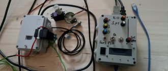
Diagram for connecting a voltmeter-ampmeter to an adjustable power supply. At the bottom of the circuit, the fan and the Chinese voltmeter-ampmeter are connected through an LCV voltage stabilizer to the output of the diode bridge in parallel with capacitor C1.
It was not immediately and at the right time that it became clear that its power input was galvanically connected to the minus input of the shunt. Chinese voltmeter - ammeter after modification Here it turned out that the wirewound resistor, instead of the recommended resistance of 0.08 Ohm, has 0.8 Ohm.
It is more expensive than previous models, but also has a higher upper limit of measurements in V. It was possible, of course, to install another duty station and power the indicator from it, but it seemed to me too bold and I decided to hack the indicator itself. How to connect a Chinese ammeter voltmeter
How to properly connect a voltmeter
Anyone who does not know, but wants to check the voltage on some part of the electrical network, must ask the question - how to connect a voltmeter? This is actually a serious question, the answer to which lies in a simple requirement - the voltmeter must be connected only in parallel with the load. If a serial connection is made, the device itself will simply fail and you may receive an electric shock.
The thing is that with such a connection the current strength acting on the measuring device itself decreases. At this resistance, it does not change, that is, it remains large. By the way, never confuse a voltmeter with an ammeter. The latter is connected to the circuit in series to reduce the resistance to a minimum.
Homemade voltmeter for batteries
In today's lesson we will look at the option of making a homemade digital voltmeter to measure the voltage on a single battery. Voltage measurement limits 1-4.5 Volts. External additional power, other than the one being measured, is not required. 25 years ago I had a cassette player. I powered it with Ni-Cd batteries NKGTs-0.45 with a capacity of 450 mAh. In order to determine on the road which batteries have already run out and which ones will still work, a simple device was made.
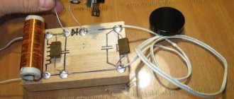
Battery-rechargeable diagnostic and measuring complex.
It is assembled using a voltage converter circuit using two transistors. The LED is turned on at the output. A resistor wound from nichrome is connected parallel to the input connected to the battery. Thus, if the battery is capable of delivering about 200mA, then the LED lights up.
One of the disadvantages is that the contact sizes are rigidly curved to the length of the AA element; it is not convenient to connect all other standard sizes. Well, the tension is not visible. Therefore, in the age of digital technology, I wanted to make a more high-tech device. And of course on a microcontroller, where would we be without it? 
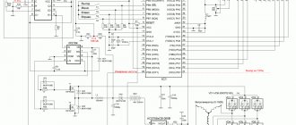
So, here is the diagram of the designed device.
Parts used: 1. OLED display with a diagonal of 0.91 inches and a resolution of 128x32 (about $3) 2. ATtiny85 microcontroller in SOIC package (about $1) 3. Boost DC/DC Converter LT1308 from Linear Technology. ($2.74 for 5 pieces) LT1308 manual 4. Ceramic capacitors, soldered from a faulty video card. 5. Inductance COILTRONICS CTX5-1 or COILCRAFT DO3316-472. 6. Schottky diode, I used MBR0520 (0.5A, 20V)
Voltage converter LT1308
Characteristics from the LT1308 description:
They promise 300mA 3.3V from one NiCd element, which suits us.
The output voltage is set by a divider, resistors 330 kOhm and 120 kOhm, with the indicated ratings the output voltage of the converter is about 4.5V. The output voltage was chosen to be sufficient to power the controller and display, slightly higher than the maximum measured voltage on the lithium battery. To unlock the full potential of the voltage converter, you need inductance, which I don’t have (see point 5 above), so the converter I assemble has obviously worse parameters. But my workload is quite small. When connecting a real load from a microcontroller and an OLED display, the following load table is obtained. Great, let's move on.
Features of voltage measurement with a microcontroller
The ATtiny85 microcontroller has a 10-bit ADC. Therefore, the read level lies in the range 0-1023 (2^10 ). To convert to voltage, the code is used: float Vcc = 5.0; int value = analogRead(4); / read the readings from A2 float volt = (value / 1023.0) * Vcc; Those. It is assumed that the supply voltage is strictly 5V. If the microcontroller's supply voltage changes, the measured voltage will also change. Therefore, we need to know the exact value of the supply voltage! Many AVR chips including the ATmega and ATtiny series provide a means of measuring internal reference voltage. By measuring the internal reference voltage, we can determine the value of Vcc. Here's how:
- Set analogReference(INTERNAL).
- Take ADC readings for the internal 1.1 V source.
- Calculate the Vcc value based on the 1.1 V measurement using the formula:
Vcc * (ADC readings) / 1023 = 1.1 V From which it follows: Vcc = 1.1 V * 1023 / (ADC readings) A function for measuring the controller supply voltage was found on the Internet: Function readVcc()
long readVcc() { // Read 1.1V reference against AVcc // set the reference to Vcc and the measurement to the internal 1.1V reference #if defined(__AVR_ATmega32U4__) || defined(__AVR_ATmega1280__) || defined(__AVR_ATmega2560__) ADMUX = _BV(REFS0) | _BV(MUX4) | _BV(MUX3) | _BV(MUX2) | _BV(MUX1); #elif defined (__AVR_ATtiny24__) || defined(__AVR_ATtiny44__) || defined(__AVR_ATtiny84__) ADMUX = _BV(MUX5) | _BV(MUX0); #elif defined (__AVR_ATtiny25__) || defined(__AVR_ATtiny45__) || defined(__AVR_ATtiny85__) ADMUX = _BV(MUX3) | _BV(MUX2); #else ADMUX = _BV(REFS0) | _BV(MUX3) | _BV(MUX2) | _BV(MUX1); #endif delay(75); // Wait for Vref to settle ADCSRA |= _BV(ADSC); // Start conversion while (bit_is_set(ADCSRA,ADSC)); // measuring uint8_t low = ADCL; // must read ADCL first — it then locks ADCH uint8_t high = ADCH; // unlocks both long result = (high<<8) | low; result = 1125300L / result; // Calculate Vcc (in mV); 1125300 = 1.1*1023*1000 return result; // Vcc in millivolts }
For screen output, the Tiny4kOLED library with a 16x32 font included is used.
To reduce the size of the library, 2 unused characters (, and -) were removed from the font and the missing letter “B” was drawn. The library code has been changed accordingly. Also, to stabilize the output measurements, a function from the Arduino forum was used, thanks to the author dimax
, it works well.
I debugged the code on a Digispark board in the arduino IDE. After which the ATtiny85 was desoldered and soldered onto the breadboard. We assemble a breadboard, use a trimmer to set the voltage at the output of the converter (at first I set the output to 5V, while the current at the input of the converter was 170mA, I reduced the voltage to 4.5V, the current dropped to 100mA). When the ATtiny85 is soldered to the breadboard, the code has to be uploaded using a programmer, I have a regular USBash ISP.
Program code
// SETUP /* * Set #define NASTROYKA 1 * Compile, upload the code, run, remember the value on the display, for example 5741 * We measure the real voltage at the output of the converter with a multimeter, for example 4979 (this is in mV) * Count (4979/5741)* 1.1=0.953997 * Calculate 0.953997*1023*1000 = 975939 * Write the result in line 100 in the form result = 975939L * Set #define NASTROYKA 0 * Compile, upload the code, run, done. */ #define NASTROYKA 0 #include #include long Vcc; float Vbat; // fine-tuning the smoothing algorithm shumodav() #define ts 5 // *table size* number of rows of the array for storing data, for deviation ± 2 counts, optimally 4 rows and one in reserve. #define ns 25 // *number samples*, from 10..to 50 maximum number of samples for analysis of the 1st part of the algorithm #define ain A2 // which analog input to read (A2 is P4) #define mw 50 // *max wait* from 15..to 200 ms wait for the countdown to be repeated for part 2 of the algorithm unsigned int myArray[ts][2], aread, firstsample, oldfirstsample, numbersamples, rezult; unsigned long prevmillis = 0; boolean waitbegin = false; //flag of the enabled countdown repeat waiting counter void setup() { oled.begin(); oled.clear(); oled.on(); oled.setFont(FONT16X32_sega); } void loop() { for (byte i = 0; i < 5; i++) { Vcc += readVcc(); } Vcc /= 5; noisedav(); Vbat = ((result / 1023.0) * Vcc) / 1000; if (Vbat >= 0.95) { oled.setCursor(16, 0);#if NASTROYKA oled.print(rezult); #else oled.print(Vbat, 2); oled.print("/"); #endif } Vcc = 0; } long readVcc() { // read the real supply voltage // Read 1.1V reference against AVcc // set the reference to Vcc and the measurement to the internal 1.1V reference #if defined(__AVR_ATmega32U4__) || defined(__AVR_ATmega1280__) || defined(__AVR_ATmega2560__) ADMUX = _BV(REFS0) | _BV(MUX4) | _BV(MUX3) | _BV(MUX2) | _BV(MUX1); #elif defined (__AVR_ATtiny24__) || defined(__AVR_ATtiny44__) || defined(__AVR_ATtiny84__) ADMUX = _BV(MUX5) | _BV(MUX0); #elif defined (__AVR_ATtiny25__) || defined(__AVR_ATtiny45__) || defined(__AVR_ATtiny85__) ADMUX = _BV(MUX3) | _BV(MUX2); #else ADMUX = _BV(REFS0) | _BV(MUX3) | _BV(MUX2) | _BV(MUX1); #endif delay(75); // Wait for Vref to settle ADCSRA |= _BV(ADSC); // Start conversion while (bit_is_set(ADCSRA, ADSC)); // measuring uint8_t low = ADCL; // must read ADCL first — it then locks ADCH uint8_t high = ADCH; // unlocks both long result = (high << | low; // result = 1125300L / result; // Calculate Vcc (in mV); 1125300 = 1.1*1023*1000 // indicator showed 4990, voltmeter 4576mV (4576/4990 )*1.1=1.008737 result = 1031938L / result; // Calculate Vcc (in mV); 1031938 = 1.008737*1023*1000 return result; // Vcc in millivolts } void shumodav() { // main function // fill the table with zeros at the beginning of the for loop (int s = 0; s < ts; s++ ) { for (int e = 0; e < 2; e++) { myArray[s][e] = 0; } } // main data accumulation loop for (numbersamples = 0; numbersamples < ns; numbersamples++) { #if NASTROYKA aread = readVcc(); #else aread = analogRead(ain); #endif // leave to work with the table //// tablework(); } // filled array, calculate the maximum repeating value int max1 = 0; // temporary variable to store maxima for (byte n = 0; n < ts ; n++) { if (myArray[n][1] > max1) { //search 2- x row elements max1 = myArray[n][1]; // remember where the most hits firstsample = myArray[n][0]; // its 1 element = intermediate result. } } //*****second phase of the algorithm ********///// // if the old sample is not equal to the new one, //and there was no time count enable flag, then if (oldfirstsample != firstsample && waitbegin == false) { prevmillis = millis(); // reset the time counter to the beginning waitbegin = true; } // activate the wait flag // if before the time limit expires the countdown is equal // to the old one, then remove the flag if (waitbegin == true && oldfirstsample == firstsample) { waitbegin = false; result = firstsample; } // if the countdown is still not equal and the waiting time has expired if (waitbegin == true && millis() - prevmillis >= mw) { oldfirstsample = firstsample; waitbegin = false; result = firstsample; } //then we recognize the new sample as the final result of the function. } // end of the main function void tablework() { // function for entering data into the table // if the count in the table matches, then increment // its counter in the second element for (byte n = 0; n < ts; n++) { if (myArray[n][0] == aread) { myArray[n][1] ++; return; } } // go through the cells to write the value aread to the table for (byte n = 0; n < ts; n++) { if (myArray[n][0] == 0) { //if there is an empty string myArray[n ][0] = ready; return; } } // if suddenly the entire table is filled before the loop ends, numbersamples = ns; } // then the cycle counter is at maximum
As mentioned above, the controllers have an internal 1.1V reference voltage. It is stable, but not accurate. Therefore, its actual voltage most likely differs from 1.1V. To find out how much it actually is, you need to calibrate:
* Set #define NASTROYKA 1 * Compile, upload the code, run it, remember the value on the display, for example 5741 * Use a multimeter to measure the real voltage at the output of the converter, for example 4979 (this is in mV) * Calculate (4979/5741)*1.1=0.953997 - this real voltage of the reference voltage source * Calculate 0.953997*1023*1000 = 975939 * Write the result in line 100 as result = 975939L; * Set #define NASTROYKA 0 * Compile, upload the code, run, done.
Using the DipTrace program we lay out a board the size of an OLED display 37x12mm
Half an hour of unloved LUT activity.
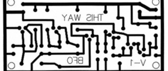
Find 10 differences
The first time I screwed up and etched the mirror board, I only noticed it when I started soldering the elements.
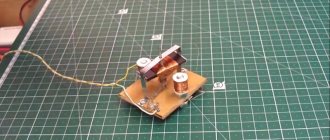
Solder it. SMD inductance 4.7 μH was kindly provided to me by SS_SerG, thank you very much, Sergey.
We assemble a sandwich from a board and a screen. I soldered small magnets at the ends of the wires; the voltmeter itself snaps onto the battery being measured. Neodymium magnets lose their magnetic properties when heated above 80 degrees, so they need to be soldered with a low-melting Wood or Rose alloy very quickly. We perform calibration again and check the accuracy of the measurement:
Bonus
I cheated, there is no bonus, sorry. Anticipating comments that a device with similar and even better functionality can be bought on Ali, I immediately agree without trading. Here it is, searched for by the name BT-168D. Costs about $4.
The program code, OLED display library and printed circuit board can be downloaded BY LINK
Thank you for your attention, good luck to everyone.
Schematic diagram of a voltmeter
Now closer to the diagram. Figure 1 shows a circuit of a voltmeter that measures voltage from 0 to 100V (0.99.9V). The measured voltage is supplied to pins 11-10 (input) of microcircuit D1 through a divider on resistors R1-R3.
The SZ capacitor eliminates the influence of interference on the measurement result. Resistor R4 is used to set the instrument readings to zero; in the absence of input voltage, and resistor R5 is used to set the measurement limit so that the measurement result corresponds to the real one, that is, we can say that they calibrate the device.
Rice. 1. Schematic diagram of a digital voltmeter up to 100V on SA3162, KR514ID2 microcircuits.
Now about the outputs of the microcircuit. The logical part of the CA3162E is built using TTL logic, and the outputs are also with open collectors. At the outputs “1-2-4-8” a binary decimal code is generated, which changes periodically, providing sequential transmission of data on three digits of the measurement result.
If a TTL decoder is used, such as KR514ID2, then its inputs are directly connected to these inputs of D1. If a CMOS or MOS logic decoder is used, then its inputs will need to be pulled to positive using resistors. This will need to be done, for example, if the K176ID2 or CD4056 decoder is used instead of KR514ID2.
The outputs of the decoder D2 are connected through current-limiting resistors R7-R13 to the segment terminals of the LED indicators H1-NC. The same segment pins of all three indicators are connected together. To poll the indicators, transistor switches VT1-VT3 are used, to the bases of which commands are sent from the outputs H1-NC of the D1 chip.
Read also: Magstrong 450 drilling and tapping
These conclusions are also made according to an open collector circuit. Active zero, so transistors of the pnp structure are used.
MINI DIGITAL VOLTMETERS
Another small victory of China-industry over domestic amateur radio occurred in the field of A/V meters. Mini LED voltage indicators have become very popular for several years now. They can already be seen in many home-made designs, and making a digital voltmeter / ammeter on a microcontroller from scratch is more likely to fall under the category of “masochism,” unless, of course, special properties or accuracy are required. So it makes sense to take a closer look at such modules, choosing the smallest of them in three different colors for the test.
What you will need
— Arduino Uno microcontroller — LCD text screen — a pair of 10 kOhm resistors — rectifier diode — terminal block — breadboard — male-to-male connecting wires
The Arduino Uno microcontroller can measure voltage on contacts for connecting analog devices. The board is designed for direct current up to 5 volts; higher voltages may damage the board. Some batteries produce more, for example “Krona” - 9 volts. In order not to damage the board, I will add a simple voltage divider - it will allow you to cope with 10 volts.
I’ll assemble a voltmeter on a breadboard: this way I can quickly change the circuit, add new parts and correct errors. It's much more difficult with a soldering iron.
Details
Perhaps the most difficult to obtain are CA3162E microcircuits. Of the analogues, I know only NTE2054. There may be other analogues that I am not aware of.
The rest is much easier. As already said, the output circuit can be made using any decoder and corresponding indicators. For example, if the indicators have a common cathode, then you need to replace KR514ID2 with KR514ID1 (the pinout is the same), and drag the transistors VT1-VTZ down, connecting their collectors to the power supply negative, and the emitters to the common cathodes of the indicators. You can use CMOS logic decoders by connecting their inputs to the power supply positive using resistors.
Mini volt-amp meters
A more expensive analogue is indicators that simultaneously display voltage and current. They differ slightly in the connection diagram and the presence of two reading correction resistors on the board.
Forum for discussing the material MINI DIGITAL VOLTMETERS
How does a lithium-ion battery work and how does it differ in physical and chemical properties from other types. Interesting theory. AIMTEC AMSR and AMSRI switching voltage regulators are an excellent replacement for the popular 78xx / 79xx microcircuits. Homemade active pre-amplifier with low-frequency and high-frequency adjustments on the TL072 op-amp, for UMZCH.
Source
BY42A connection diagram
Those who need high measurement accuracy can use the BY42A . Such a device will give one more decimal place.
The BY42A voltmeter-ampmeter is designed for a higher measured voltage - up to 200 V, but the supply voltage of the device should be in the range of 3.8-30 V.
BY42A can also be found in two board versions, but the color marking of the wires remains the same.
Using a voltammeter in your car charger, you can not only visually monitor the battery charging process, but also timely diagnose the condition of the battery. It will be enough to connect the charger, where the voltammeter is installed, to the battery, and we will see what voltage is currently on it.