Electronics enthusiasts are probably familiar with such a device as a multimeter, with which you can measure voltage, current, resistance, etc. The multimeter handles all this quite easily. But sometimes electronics enthusiasts need to measure inductance and capacitance, and a regular multimeter can no longer cope with this task. Specialized multimeters have been created for this purpose, but they are much more expensive than regular ones.
On our website we have already looked at creating a capacitance meter, a frequency meter and a resistance meter (ohmmeter) based on the Arduino board. And in this article we will look at creating a capacitance and inductance meter (Inductance LC Meter) based on the Arduino board. We will display the measured values of capacitance and inductance on a 16x2 LCD display screen. A button in the project diagram will be used to switch between capacitance and inductance measurement mode.
Required Components
- Arduino Uno board (buy on AliExpress).
- 741 operational amplifier chip.
- LCD display 16x2 (buy on AliExpress).
- A 3v battery (to power the op amp) and a power supply for the rest of the circuit.
- 100 Ohm resistor (buy on AliExpress).
- Capacitors (buy on AliExpress).
- Inductance.
- Diode 1n4007 (buy on AliExpress).
- 10 kOhm resistor (buy on AliExpress).
- Potentiometer 10 kOhm (buy on AliExpress).
- Button.
- Breadboard or printed circuit board and connecting wires.
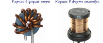
The appearance of some of the components used in the project is shown in the following figure.
How to recalculate inductors (single-layer, cylindrical)
The need to recalculate the inductors arises when the required wire diameter specified in the design description is not available and it is replaced with a wire of a different diameter; when changing the diameter of the coil frame.
If there is no wire of the required diameter, which is the most common reason for recalculating coils, you can use a wire of a different diameter.
A change in the diameter of the wire up to 25% in one direction or another is quite acceptable and in most designs does not affect the quality of their work. Moreover, increasing the diameter of the wire is permissible in all cases, since it reduces the ohmic resistance of the coil and increases its quality factor.
Reducing the diameter worsens the quality factor and increases the current density per unit cross-section of the wire, which cannot be more than a certain permissible value.
The number of turns of a single-layer cylindrical coil is recalculated when replacing a wire of one diameter with another using the formula:
Where:
- n is the new number of coil turns;
- n1 - number of coil turns specified in the description;
- d—diameter of the existing wire;
- d1 - wire diameter specified in the description.
As an example, let us recalculate the number of turns of the coil shown in Fig. 1, for wire with a diameter of 0.8 mm:
(winding length l= 18 X 0.8 = 14.4 mm, or 1.44 cm).
Thus, the number of turns and winding length have decreased slightly. To check the correctness of the recalculation, it is recommended to perform a new calculation of the coil with a changed wire diameter:
When recalculating a coil due to a change in its diameter, one should use the percentage relationship between the diameter and the number of turns of the coil.
This relationship is as follows: when the diameter of the coil increases by a certain number of percent, the number of turns decreases by the same percentage, and, conversely, when the diameter decreases, the number of turns increases by an equal number of percent. To simplify calculations, you can take the diameter of the frame as the diameter of the coil.
Rice. 2. Inductors. Example.
So, for example, let's recalculate the number of turns of a coil (Fig. 2, a), which has a diameter of 1.5 cm, to a diameter equal to 1.8 cm (Fig. 2, b). According to the conversion conditions, the diameter of the frame increases by 3 mm, or 20%.
Consequently, to maintain a constant value of the inductance of this coil when winding it on a frame of larger diameter, it is necessary to reduce the number of turns by 20%, or by 8 turns. Thus, the new coil will have 32 turns.
Let's check the recalculation and determine the error made as a result of the recalculation. The coil (see Fig. 2, a) has the inductance:
New reel on a frame with an increased diameter:
The error in recalculation is 0.25 μH, which is quite acceptable for calculations in amateur radio practice.
Calculation of frequency and inductance
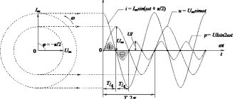
In this project we will measure capacitance and inductance using an LC circuit connected in parallel - that is, in fact, this is a well-known LC circuit. This circuit can be compared to a bell that begins to resonate at a certain frequency. When a pulse is applied to this circuit, it begins to resonate and a sinusoidal oscillation is formed at its output at the resonant frequency. We need to convert this sine wave into a square wave. To do this, we will use a 741 operational amplifier, which will convert the sine wave into a train of square wave pulses with a duty cycle of 50%. We will then measure the frequency of these pulses using the Arduino board and then through a series of mathematical transformations we can determine the inductance or capacitance that is being measured. To do this, we will use the usual formula relating frequency and time for a square wave:
f=1/(2*time)
where time will be determined using the pulseIn() function.
We also know the formula for calculating the frequency of the LC circuit:
f=1/2*Pi* square root of (LC)
square root – square root.
From this expression we can express the inductance L:
f2 = 1/ (4Pi2LC) L= 1/ (4Pi2 f2C) L = 1/(4* Pi * Pi * f * f * C)
Since the sine wave from the output of the LC circuit has the same duration of the positive and negative half-waves, the op-amp comparator converts it into a square wave (a train of square pulses) with a duty cycle of 50% - we can measure the frequency of this square wave using the pulseIn() function in Arduino. This function will give us a time period, which we will then convert into a frequency value using the above formula. Since the pulseIn function measures only one pulse, therefore, in order to get the correct frequency value, we multiply it by 2 in the formula. And when we have a frequency value, we will determine the inductance value using the formula for the LC circuit.
Note : While measuring inductance (L1), capacitance C1) in our project should be 0.1uF, and while measuring capacitance (C1), inductance (L1) should be 10mH. If you want to change these values, you will need to make appropriate changes to the program code.
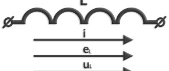
Solenoid inductance
Solenoid-shaped coil (finite length).
A solenoid is a long, thin coil, that is, a coil whose length is much greater than its diameter (also in further calculations here it is implied that the thickness of the winding is much less than the diameter of the coil). Under these conditions and without the use of magnetic material, the magnetic flux density (or magnetic induction) B{\displaystyle B}, which is expressed in SI units of tesla, inside the coil is effectively constant and is (approximately) equal to
B=μNil{\displaystyle \displaystyle B=\mu _{0}Ni/l}
or
B=μni,{\displaystyle \displaystyle B=\mu _{0}ni,}
where μ{\displaystyle \mu _{0}} is the magnetic constant, N{\displaystyle N} is the number of turns, i{\displaystyle i} is the current written in amperes, l{\displaystyle l} is the length of the coil in meters and n{\displaystyle n} is the winding density of turns in . Neglecting edge effects at the ends of the solenoid, the flux linkage through the coil is equal to the flux density B{\displaystyle B} multiplied by the cross-sectional area S{\displaystyle S} and the number of turns N{\displaystyle N}:
Ψ=μN2iSl=μn2iV,{\displaystyle \displaystyle \Psi =\mu _{0}N^{2}iS/l=\mu _{0}n^{2}iV,}
where V=Sl{\displaystyle V=Sl} is the volume of the coil. From this follows the formula for the inductance of the solenoid (without a core):
L=μN2Sl=μn2V.{\displaystyle \displaystyle L=\mu _{0}N^{2}S/l=\mu _{0}n^{2}V.}
If the coil inside is completely filled with magnetic material (core), then the inductance differs by a factor μ{\displaystyle \mu } - the relative magnetic permeability of the core:
L=μμN2Sl=μμn2V.{\displaystyle \displaystyle L=\mu _{0}\mu N^{2}S/l=\mu _{0}\mu n^{2}V.}
In the case when μ>>1{\displaystyle \mu >>1}, one can (should) under S
understand the cross-sectional area of the core and use this formula even with thick winding, unless the total cross-sectional area of the coil exceeds the cross-sectional area of the core many times.
Circuit operation
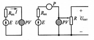
The circuit of a capacitance and inductance meter based on an Arduino board is shown in the following figure.
The Arduino board in this circuit controls all processes. To measure capacitance or inductance, an LC circuit consisting of a capacitor and an inductor is used. To convert the sine wave from the LC output into a square wave, we have used a 741 op amp. For this we have to apply a negative supply voltage to the op amp - for this purpose we use a 3V battery connected in negative polarity. This means that the negative terminal of the 741 IC is connected to the negative terminal of the battery, and the positive terminal of the battery is connected to the ground of the circuit.
The button in the circuit is used to change the mode - measuring capacitance or inductance. LCD display is used to display measurement results. The potentiometer is designed to control the brightness of the LCD display. The circuit is powered from the 5v pin of the Arduino board, and the Arduino board itself can be powered via a USB cable from the computer or using a 12 V adapter.
The appearance of the circuit assembled on a breadboard is shown in the following figures, and they also show an example of the operation of the circuit in capacitance measurement mode and inductance measurement mode.
Solenoid inductance
Solenoid-shaped coil (finite length).
A solenoid is a coil whose length is much greater than its diameter (also in further calculations it is assumed that the thickness of the winding is much less than the diameter of the coil). Under these conditions and without the use of a magnetic core, the magnetic flux density (or magnetic induction) B{\displaystyle B}, which is expressed in SI units of tesla, inside the coil away from its ends is (approximately) equal to
B=μNil{\displaystyle \displaystyle B=\mu _{0}Ni/l}
or
B=μni,{\displaystyle \displaystyle B=\mu _{0}ni,}
where μ{\displaystyle \mu _{0}} is the magnetic constant, N{\displaystyle N} is the number of turns, i{\displaystyle i} is the current in amperes, l{\displaystyle l} is the length of the coil in meters and n {\displaystyle n} - winding density of turns in . Neglecting edge effects at the ends of the solenoid, the flux linkage through the coil is equal to the flux density B{\displaystyle B} multiplied by the cross-sectional area S{\displaystyle S} and the number of turns N{\displaystyle N}:
Ψ=μN2iSl=μn2iV,{\displaystyle \displaystyle \Psi =\mu _{0}N^{2}iS/l=\mu _{0}n^{2}iV,}
where V=Sl{\displaystyle V=Sl} is the volume of the coil. From this follows the formula for the inductance of the solenoid (without a core):
L=μN2Sl=μn2V.{\displaystyle \displaystyle L=\mu _{0}N^{2}S/l=\mu _{0}n^{2}V.}
If the coil inside is completely filled with a magnetic core, then the inductance differs by a factor μ{\displaystyle \mu } - the relative magnetic permeability of the core:
L=μμN2Sl=μμn2V.{\displaystyle \displaystyle L=\mu _{0}\mu N^{2}S/l=\mu _{0}\mu n^{2}V.}
In the case when μ>>1{\displaystyle \mu >>1}, under S
You can understand the cross-sectional area of the core and use this formula even with thick winding, unless the total cross-sectional area of the coil exceeds the cross-sectional area of the core many times.
Photo of the assembled project from a reader of our site
A reader of our site (his name is Alexander) assembled the capacitance and inductance meter project described in this article based on the Arduino board and decided to share with us photographs of the assembled project, for which we express our deep gratitude to him.
Here the pictures are presented in compressed form (they are clickable) in order to save Internet traffic; in original quality you can download them from Yandex.disk or from Google drive (link in the comments).
Application of coils in technology
The phenomenon of electromagnetic induction has been known for a long time and is widely used in technology. Examples of using:
- smoothing out ripples and interference, storing energy;
- creation of magnetic fields in various devices;
- feedback circuit filters;
- creation of oscillatory circuits;
- transformers (a device of two coils connected inductively);
- power electrical engineering uses to limit the current during a short circuit. on power lines (inductors called reactors);
- limiting the current in welding machines - inductance coils make its operation more stable, reducing the arc, which allows you to get an even welding seam that has the greatest strength;
- the use of coils as electromagnets of various actuators;
- electromagnetic relay windings;
- induction furnaces;
- establishing the quality of iron ores, studying rocks by determining the magnetic permeability of minerals.
Work on direct and alternating current
The magnetic field that is created inside the coil is directed along the axis and is equal to:
B= µ0nI,
where µ0 is the magnetic permeability of the vacuum, n is the number of turns, and I is the current value.
When current moves through the solenoid, the coil stores energy, which is equal to the work required to establish the current. To calculate the inductance in this case, the following formula is used:
E = LI2 :2,
where L shows the inductance value, and E is the stored energy.
Self-induced emf occurs when the current in the solenoid changes.
When operating on alternating current, an alternating magnetic field appears. The direction of the gravitational force may change or remain unchanged. The first case occurs when using a solenoid as an electromagnet. And the second, when the anchor is made of soft magnetic material. An AC solenoid has a complex resistance that includes the winding resistance and its inductance.
The most common application of solenoids of the first type (direct current) is as a translational power electric drive. The strength depends on the structure of the core and body. Examples of use include the operation of scissors in cutting receipts in cash registers, valves in engines and hydraulic systems, and lock tabs. Solenoids of the second type are used as inductors for induction heating in crucible furnaces.
Logs
I struggled for a long time with how to record what was happening inside the microcontroller, because it has very little memory.
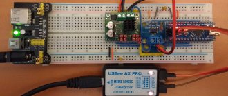
As a result, I discovered that the native SPI interface is very fast, and as a result, all debugging information is transmitted by the microcontroller via the SPI interface; a widely available ($10 on Dilextreme, $6 on AliExpress) Chinese clone of the Saelae Pro 8 Logic logic analyzer was used to record it. After very simple manipulations of flashing VID/PID, it can be used with native software from Saelae. I use sigrok (pulseview). It has an extremely simple log file format, which I simply read with my homemade fifty-line program. I bought this analyzer on the advice of gbg, who repaired my Spectrum remotely for me (thank you very much!), and I consider it the best investment in the last two years. For example, I applied a sinusoidal signal (in PWM) to the output of the controller, and the logic analyzer sees it perfectly:
All this was put together, the photo is given in the title of the post.
Almost all the articles that I post here are my work diary. I learn something (in this case management theory) and diligently write down what I learn. The best way to write it down is to write an explanation of how it all works. Then I post the articles on different platforms, for example here.
I have two goals when writing text:
a) get feedback from people who know more than me.
For example, almost everything that I learned for these two articles was told to me by dear Arastas, please love and favor: a person who spends his personal time teaching idiots like me.
Again, gbg, who wrote me linear algebra for my computer graphics lectures, and then debugged the electronics for me over the phone many thousands of kilometers away.
b) just write:
This way I get a library of personal experience, which I return to periodically.
By the way, thematic media, what percentage of authors agree to your support program terms?
Fourier transform
The first thing you need to understand when reading my texts is that I believe that a function and a vector are the same thing.
All the talk about infinity bores me and obscures the essence of what is happening. Generalized functions and the like are a way of looking at pathological cases using the same language as cases where there is no pathology. It’s just that I’m not interested in pathologies. Valery Ivanovich Opoytsev (Boss) spoke well on this topic:
In any field, it is useful to be in a suitable environment of oral communication, where the bookish husks fall off.
Sometimes nothing changes in essence, but there is a feeling of falling into a rut and liberation from dogma. For science, which is always wearing a mask, this is especially important. The essence is behind the scenes, before the eyes - lace. And there is always something missing. Either simplicity, or complexity, but you can’t determine exactly what. Something is moving somewhere, you are on the sidelines, and time is disappearing into the sand, not to mention life. Next, an attempt is made to move the situation forward by simulating a writing environment where the “veils fall away.” The external outline of the content is more or less unclear from the table of contents, but the main goal is what is behind the scenes. Remove the veil, makeup, remove the decorations. Oversimplify, even lie a little, because dosing the truth is the cornerstone of explanation. The results, overloaded with details, do not fit where they should. The epiphany happens when the plump head falls to the level of “two times two”, while the count goes on in the millions. Such is the dialectic here.
If we have a vector (7,12,18,-2), then it can be considered as a set of coefficients in a weighted sum.
7*(1,0,0,0) + 12*(0,1,0,0) + 18*(0,0,1,0) + (-2)*(0,0,0,1) . In exactly the same way, we can consider this vector to be the values of the function at points 0, 1, 2, 3, because our vectors (0,1,0,0) and similar ones can be considered as a shift of a unit impulse: If we constantly increase the number of vectors (shifted unit impulses ) in the basis, we get the usual functions. Unfortunately, such a basis can be quite inconvenient to work with. Let's take the following function as an example:
We have already talked about what the Fourier transform is. In short, this is a change of basis.
In our case, the Fourier transform is a function from real numbers to complex numbers:
A function's argument (real number) is simply the number of the basis function or vector (actually, a pair of basis functions), and its value is the corresponding (pair of) coordinates in for those two vectors in the basis. The Fourier basis is the sines and cosines of various frequencies. The frequency is the number of the basis function.
For our specific function f(t), which is already a weighted sum of sine and cosine, it is very easy to calculate its expansion into a Fourier basis:
That is, our function f(t) has zero coordinates for all basis vectors, except for vectors number 11 and 41.
How is the Fourier basis useful? For example, because the differentiation operation linearly transforms this basis. Let's say we want to calculate the Fourier transform of the derivative f'(t). How to do it? As an option, straight forward: first calculate the derivative, and then calculate the Fourier transform:
Obviously, when differentiating sin(x), it will become sin(x+90°), that is, it is extremely easy to find a correspondence between the Fourier basis expansion of the original function and its derivative: Multiplication by
i
is simply a rotation of the complex plane, which corresponds to +90° in the argument of our function. That is, the differentiation operation, which is difficult to do in the basis of unit impulses, in the Fourier basis is simply scaling and rotating by 90 degrees. Beautiful, is not it?
Laplace transform
Approximately the same story happens with the Laplace transform.
Unfortunately, unlike the Fourier basis, the Laplace basis is non-orthogonal, and therefore is a little more complex for intuitive understanding. Well, that's not the point. Laplace went a little further. If Fourier had only sinusoids in his basis, then Laplace had sinusoids with exponential decay in his basis. Where did he get them from? This is extremely, extremely useful for solving linear differential equations. Let's think about what function transforms into itself upon differentiation? Exhibitor. What about differentiation twice? Sinus. And their combinations give all possible functions that can appear when solving (linear) diffuses, which is what the Marquis de Laplace used. We will not go into details of how these properties are derived (it’s better to carefully consider the properties of the Fourier basis, it is simpler), let’s just note the following facts:
1. Laplace transform is linear:
2. The Laplace transform of the derivative is an affine action on the transformation of the function itself: 3. So, if we have a DC motor, then the flowing current I(t) and the terminal voltage U(t) are related by the following differential equation, where w(t ) is the speed of rotation of the motor shaft: Here L is the inductance and R is the resistance, which is what we are looking for. I will not repeat where this diffuser comes from, since I have already described it in detail and on my fingers (see “Maxwell’s equations on my fingers”).
Since our task is to find L and R, let's rigidly fix the motor shaft, thus forcing w(t) to be zero:
On the advice of Arastas, I supplied two types of signals to my engine: a square wave and a sine wave. Then I measured the current flowing, the picture looks something like this:
Here the blue traces are the input voltage that I am monitoring, and the green ones are the current measurements taken with the ACS714.
My microcontroller code, which generates 11 experiments with square waves and sinusoids of various amplitudes and frequencies, can be viewed here.
Let's solve our differential equation for both types of voltage signal, obtain a parametric current output, and adjust the parameters so that the theoretical curve approximates the actual measurements as best as possible.
Input signal - sine
Let's repeat the procedure for a voltage sinusoid with amplitude U0 and frequency F0.
Let's apply the Laplace transform to equation (1), first to the right side: and then to the left: Now the inverse transformation will give us the following law of current flow: Again, a quick sanity check: zero current at the very beginning, a few milliseconds of transient processes (an exponential directly dependent from inductance). After some time, the current flowing is the weighted sum of the sine and cosine of the same frequency (the frequency is equal to the input, this is good). This sum gives a sinusoid slightly shifted in time. Great, the result is plausible. The measurements are here, and the code for selecting parameters is here. It gives approximately the same values of resistance and inductance, which is what we needed. Here's the chart:
Why not measure the parameters directly, why all this garden with microcontrollers? Firstly, I have nothing to measure inductance with. Yes, and measuring engine resistance with an ohmmeter can have its own nuances.
Further, the parameters found at high signal amplitude do not exactly coincide with what is obtained at low voltages. It may be interesting (not discussed here) to make a model not only of the motor, but of the entire system as a whole, including the nonlinearity of the PWM driver.
Well, then all that remains is to develop a regulator that will take the required current at the input. Stay in touch!
Calculation methods
There are several basic ways to determine the inductance of a coil. All formulas that will be used in the calculations can be easily found in reference books or on the Internet. The whole calculation process is quite simple and will not be difficult for people with basic mathematical and physical knowledge.
Through current
This calculation is considered the simplest way to determine the inductance of a coil. The formula through current follows from the term itself. What is the inductance of the coil can be determined by the formula: L=Ф/I, where:
- L - circuit inductance (in Henry);
- F is the magnitude of the magnetic flux, measured in webers;
- I is the current strength in the coil (in amperes).
Finite Length Solenoid
The solenoid is a thin long coil, where the thickness of the winding is significantly less than the diameter. In this case, calculations are carried out using the same formula as through current strength, only the magnitude of the magnetic flux will be determined as follows: Ф=µ0NS/l, where:
- µ0 is the magnetic permeability of the medium, determined from lookup tables (for air, which is taken by default in most calculations, it is equal to 0.00000126 henry/meter);
- N is the number of turns in the coil;
- S is the cross-sectional area of the coil, measured in square meters;
- l is the length of the solenoid in meters.
The self-induction coefficient of the solenoid can also be calculated based on the method for determining the energy of the magnetic flux of the field. This is a simpler option, but it requires some quantities. The formula for finding inductance is L=2W/I 2, where:
- W is the magnetic flux energy, measured in joules;
- I is the current strength in amperes.
Toroidal core coil
In most cases, a toroidal coil is wound on a core made of a material with high magnetic permeability. In this case, to calculate the inductance, you can use the formula for a straight solenoid of infinite length. It has the following form: L=N µ0 µS/2 πr, where:
- N is the number of coil turns;
- µ—relative magnetic permeability;
- µ0—magnetic constant;
- S is the cross-sectional area of the core;
- π is a mathematical constant equal to 3.14;
- r is the average radius of the torus.
Long conductor
Most of these quasi-linear conductors have a circular cross-section. In this case, the value of the self-induction coefficient will be determined by the standard formula for approximate calculations: L= µ0l (µelnl/r+ µi/4)/2 π. The following notations are used here:
- l is the length of the conductor in meters;
- r is the radius of the wire cross-section, measured in meters;
- µ0—magnetic constant;
- µi is the relative magnetic permeability characteristic of the material from which the conductor is made;
- µe is the relative magnetic permeability of the external environment (most often the value for vacuum is taken to be 1);
- π—pi number;
- ln is the notation for logarithm.
Coil quality factor
One of the most important qualities of coils is quality factor. This parameter represents the ratio of reactive (inductive) resistance to active. Active resistance is the resistance of the conductor from which the element is made; it can be considered constant, with the exception of the temperature coefficient of resistance of the material from which the wire is made.
Reactance is directly proportional to frequency. The formula for calculating the quality factor is as follows:
Where:
- π – pi number, ≈3.14,
- f – frequency,
- R – resistance.
Note! As the signal frequency increases, the quality factor of the inductor increases
Analog multimeter
This type of multimeter displays measurement readings using an arrow, under which there is a display with different scales of values. Each scale displays the readings of a particular measurement, which are signed directly on the display.
But for beginners, such a multimeter will not be the best choice, since it is quite difficult to understand all the symbols that are on the display. This may lead to incorrect understanding of the measurement results.
Business and finance
Business
: • Banks • Wealth and prosperity • Corruption • (Crime) • Marketing • Management • Investments • Securities: • Management • Open Joint Stock Companies • Projects • Documents • Securities - control • Securities - valuations • Bonds • Debts • Currency • Real estate • (Rent) • Professions • Work • Trade • Services • Finance • Insurance • Budget • Financial services • Loans • Companies • State enterprises • Economics • Macroeconomics • Microeconomics • Taxes • Audit Industry
:
• Metallurgy • Oil • Agriculture • Energy
Construction
• Architecture • Interior • Floors and ceilings • Construction process • Building materials • Thermal insulation • Exterior • Organization and production management
Photo blogs
Art
• Children's creativity • Paintings • Art • Congratulations • Film review • Musical world • Russian rock
World
• People of the world • The world around us • My homeland is the USSR • Nature Channel • Stones and minerals • Cooking, food • Construction and architecture • Under construction • Transport • Weapons • Military transport
beauty
• Fashion Pandia.ru • Girls and Girls
School
• Tests for the Unified State Exam • Solver books • Unified State Examination • 10th and 11th grades • Various textbooks • 4th grade • Russian language grades 5-9 • 5th grade • 6th grade • 7th grade • 8th grade
Wisdom
• Cliparts • Quotes
Author Directory (private accounts)
AutoAuto service • Auto parts • Products for auto • Auto repair centers • Auto accessories • auto parts for foreign cars • Body repair • Auto repair and maintenance • Car chassis repair • Auto chemicals • oils • technical centers • Gasoline engine repair • auto electrical repair • Automatic transmission repair • Tire fitting BusinessAutomation of business processes • Online stores • Construction • Telephone communications • Wholesale companies LeisureLeisure • Entertainment • Creativity • Catering • Restaurants • Bars • Cafes • Coffee shops • Night clubs • Literature TechnologiesAutomation of production processes • Internet • Internet providers • Communications • Information technologies • IT companies • WEB studios • Website promotion • Software sales • Switching equipment • IP telephony | InfrastructureCity • Authority • District administrations • Courts • Utilities • Teen clubs • Public organizations • City information sites The sciencePedagogy • Education • Schools • Training • Teachers GoodsTrading companies • Trade and service companies • Mobile phones • Accessories for mobile phones • Navigation equipment |