Online electrical magazine. Starting and running winding resistance
The starting (auxiliary) winding is designed to create the necessary starting torque.
According to the method of creating starting torque, single-phase electric motors can be divided into motors with a running capacitor (the capacitor is permanently connected to the starting winding) and motors with a starting capacitor (the capacitor is connected to the auxiliary winding during the start). In terms of their design, the main and starting windings have a number of differences. First of all, this is the cross-section of current-carrying conductors. The cross-section of the wires of the working winding is larger due to the long stay of the winding under load. It is this condition that is used to determine the starting and operating windings of the electric motor. The working winding has a larger conductor cross-section, and therefore less active resistance.
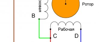
The terminal box of a single-phase electric motor has 3 or 4 terminals. To determine the starting and operating windings, it is necessary to measure the active resistance of the conductors. Sometimes the windings can be distinguished visually, knowing that the working one has a larger cross-section. The working winding is connected to the AC mains. One of the starting terminals is to the output of the working winding, the second is through a capacitor to the other end of the working winding. The direction of rotation of the motor is determined by the connection of the starting winding and does not depend on the polarity of the supply voltage.
For electric motors with 3 terminals, it is also necessary to measure active resistances. A combination of resistances of 10 Ohm, 25 Ohm and 15 Ohm is quite common. In this case, one of the terminals of the main winding will have the lowest resistance (10 Ohms), and the second, when measured with the other two terminals, will show 10 Ohms and 15 Ohms. The third pin will be the start winding pin. The direction of rotation of such a motor can be changed only by changing the winding connection diagram, for which it is necessary to disassemble the electric motor.
Total
Advantages and disadvantages
The main advantages are:
- simplicity of design;
- widespread availability of single-phase AC networks 220 V at a frequency of 50 Hz (in almost all areas).
The disadvantages include the following:
- low starting torque of the engine;
- low efficiency.
Connection diagrams for single-phase asynchronous motors
With starting winding
To connect a motor with a starting winding, you will need a button in which one of the contacts opens after switching on. These opening contacts will need to be connected to the starting winding. In stores there is such a button - this is PNDS. Its middle contact closes for the holding time, and the two outer ones remain in a closed state.
Appearance of the PNVS button and the state of the contacts after the “start” button is released"
First, using measurements, we determine which winding is working and which is starting. Typically the output from the motor has three or four wires.
Consider the option with three wires. In this case, the two windings are already combined, that is, one of the wires is common. We take a tester and measure the resistance between all three pairs. The working one has the lowest resistance, the average value is the starting winding, and the highest is the common output (the resistance of two windings connected in series is measured).
If there are four pins, they ring in pairs. Find two pairs. The one with less resistance is the working one, the one with more resistance is the starting one. After this, we connect one wire from the starting and working windings, and bring out the common wire. A total of three wires remain (as in the first option):
- one from the working winding is working;
- from the starting winding;
- general.
We work further with these three wires - we use them to connect a single-phase motor.
With all these
- Connecting a single-phase motor with a starting winding via the PNVS button
connecting a single-phase motor
We connect all three wires to the button. It also has three contacts. Be sure to place the starting wire on the middle contact (which closes only during the start), the other two - on the outermost (arbitrary). We connect a power cable (from 220 V) to the extreme input contacts of the PVNS, connect the middle contact with a jumper to the working one (note! not to the common one). That's the whole circuit for switching on a single-phase motor with a starting winding (bifilar) through a button.
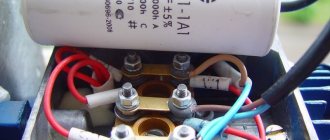
Condenser
When connecting a single-phase capacitor motor, there are options: there are three connection diagrams and all with capacitors. Without them, the engine hums, but does not start (if you connect it according to the diagram described above).
Connection diagrams for a single-phase capacitor motor
The first circuit - with a capacitor in the power supply circuit of the starting winding - starts well, but during operation the power it produces is far from rated, but much lower. The connection circuit with a capacitor in the connection circuit of the working winding gives the opposite effect: not very good performance at start-up, but good performance. Accordingly, the first circuit is used in devices with heavy starting (concrete mixers, for example), and with a working condenser - if good performance characteristics are needed.
Circuit with two capacitors
There is a third option for connecting a single-phase motor (asynchronous) - install both capacitors. It turns out something between the options described above. This scheme is implemented most often. It is in the picture above in the middle or in the photo below in more detail. When organizing this circuit, you also need a PNVS type button, which will connect the capacitor only during the start time, until the motor “accelerates”. Then two windings will remain connected, with the auxiliary winding through a capacitor.
Connecting a single-phase motor: circuit with two capacitors - working and starting
When implementing other circuits - with one capacitor - you will need a regular button, machine or toggle switch. Everything connects there simply.
Selection of capacitors
There is a rather complex formula by which you can calculate the required capacity accurately, but it is quite possible to get by with recommendations that are derived from many experiments:
- The working capacitor is taken at the rate of 70-80 uF per 1 kW of engine power;
- starting - 2-3 times more.
The operating voltage of these capacitors should be 1.5 times higher than the network voltage, that is, for a 220 volt network we take capacitors with an operating voltage of 330 V and higher. To make starting easier, look for a special capacitor for the starting circuit. They have the words Start or Starting in their markings, but you can also use regular ones.
Distinguishing types of single-phase motors in practice
Let's learn how to distinguish a bifilar motor from a capacitor motor. It should be said that the difference is purely nominal. The connection diagram for a single-phase motor is similar. The bifilar winding is not designed to operate continuously. It will interfere and reduce efficiency. Therefore, it is interrupted after a set of revolutions by a start-up relay (inherent in household refrigerators) or by centrifugal switches. It is believed that the starting winding operates for several seconds. According to generally accepted standards, it will launch 30 times per hour, lasting 3 seconds each. Then the coils may overheat (burn out). The reason that limits the starting winding being energized.
The difference is nominal, but professionals note an interesting feature by which they judge whether we have a bifilar or capacitor motor. Auxiliary winding resistance. The nominal value differs from the working one by more than 2 times, most likely the engine is bifilar. Accordingly, the winding is starting. A capacitor motor operates using the services of two coils. Both are constantly under tension.
Single phase asynchronous motor
The test must be carried out carefully; in the absence of thermal fuses and other means of protection, the starting winding may burn out. You will have to unscrew the shaft manually, which is clearly not an easy task. Sometimes it is advisable to connect a single-phase asynchronous motor to a single-phase network using a similar circuit, as was done in previous equipment. An ordinary refrigerator is equipped with a start-up relay, a separate topic of discussion. The parameters of the device are closely related to the type of engine used; mutual replacement is not possible in every case (violation of a simple rule can cause breakdown).
Let us mention it twice: there can be three or four winding terminals. The number is not informative. A pair of thermal fuse contacts is acceptable. Plus the above, including the centrifugal switch. In the case of continuity, the resistance is either low, or vice versa - we fix the gap. By the way, do not forget to test each end of the coil against the body when determining the resistance. Insulation is standard not lower than 20 MOhm. Otherwise, you should think about the presence of a breakdown. We also assume that a three-phase motor with internal star-type winding commutation may have a neutral output to the housing. In this case, the motor requires an indispensable grounding, for which a terminal is provided (but it is more likely that the motor simply failed due to an insulation breakdown).
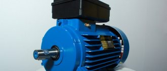
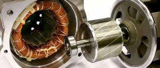
Electric motor device
Single-phase 220 V motors have two phases, but the main work is done by one, and such motors began to be called single-phase. The motor consists of the following parts.
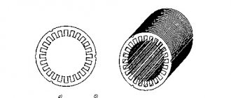
- The stator, or stationary part of the motor.
- The rotor, or the moving (rotating) part of the motor.
A single-phase electric motor can be characterized as an asynchronous electric motor, which has a working winding on its stationary part, which is connected to a single-phase alternating current network.
Trigger coil
In order for a single-phase motor to start and rotate independently, another coil is installed on them. It is designed to start the engine. The starting coil is installed in relation to the working coil with an offset of 90 degrees. In order to obtain a current shift, you should install a link in the circuit that will shift the phases. Several means can act as a phase-shifting link.
- Active resistor.
- Capacitor.
- Inductor.
The rotor and stator of the motor are metal. In order to make a rotor or stator, you need special electrical steel grade 2212.
Two and three phase motors
It is possible to connect a 2 or 3-phase motor to a single-phase power source.
Sometimes, by mistake, such motors are called single-phase. This is a misconception; it would be correct to call it “a two (or three) phase electric motor connected to a single-phase AC power supply.” Simply connecting a two or three-phase motor to a single-phase network will not work. We need a coordination scheme. There are several such circuits; matching can be achieved using capacitors. After connecting capacitors to the motor according to the diagram, the motor will work, and all phases of the motor will work, they will always be energized and perform work to rotate the rotor.
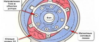
Operating principle
An alternating electric current creates a magnetic field in the stator, which has two fields, they are identical in amplitude and frequency, but in different directions. These fields act on a stationary rotor, and, due to the fact that the fields are multidirectional, the rotor begins to rotate. If there is no trigger mechanism in the motor, the rotor will stand still. The rotor, having begun to rotate in one direction, will continue to rotate in the same direction.
Starting the engine
The motor is started by means of a magnetic field; the magnetic field, acting on the rotor, forces it to rotate.
The main and additional coils create a magnetic field; the starting coil is smaller; it is connected to the additional coil through a capacitor, inductor or active resistor. If the motor is low power, the starting phase is closed. To start such an engine, you can connect electricity to the starting coil only temporarily, for no more than three seconds. There is a start button for this. The button is inserted into the trigger.
When the start button is pressed, electricity is supplied to the working and starting coils simultaneously, the engine in these first seconds of startup operates as a two-phase one, but after three seconds the rotor has already picked up speed, the motor starts, and the button is released. The supply of electricity to the starting coil stops, but the supply of electricity to the working winding does not stop, this is how the starting device is designed, then the device operates as a single-phase one.
It is important to remember that you should not hold the trigger button for long, as the trigger coil may overheat and fail; it is designed to operate for a few seconds. To ensure safety, a thermal relay and a centrifugal switch can be built into the housing of a single-phase power unit. The centrifugal switch is designed in such a way that when the rotor picks up speed, the centrifugal switch turns off itself, without human intervention. The starting current of a single-phase motor is higher than the operating one; after starting, the current decreases to the operating level. See the connection diagram for a single-phase motor here.
Operating principle
The stator windings generate magnetic fields using alternating current. They have the same amplitude and frequency, but act in different directions, so the static rotor begins to rotate.
If the motor does not have a starting mechanism, the rotor stops because the resulting torque is zero. In the case where the rotor begins to rotate in one direction, the corresponding torque becomes higher as the motor shaft continues to rotate in the given direction.
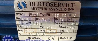
How to decide on engine type
If the engine is new, then there will be no special problems, since its nameplate indicates the engine type and other data. If the engine has been repaired, then determining its type is associated with some difficulties: the plate could simply be lost or damaged mechanically. Therefore, in such cases, it is better to know how to independently determine the type of engine.
Brushed motors
Determining whether a motor is commutator or asynchronous is not at all difficult, since they have different structures. A characteristic difference between a commutator motor is the presence of brushes that are stationary, as well as a commutator that rotates and consists of a set of copper plates. Brushes are pressed against these plates, transmitting electric current to the motor armature winding.
The advantage of such engines is that they accelerate quickly and allow you to get high speeds. In addition, by changing the polarity, it is possible to change the direction of rotation of the device. No less important can be considered the factor that you can easily organize control of the engine speed, with its adjustment within a wide range.
A significant disadvantage of commutator engines is their increased noise during operation, especially at high speeds. As for low speeds, the performance of these engines can be considered quite acceptable. It should also be taken into account that the friction of the brushes and commutator leads to wear of both the brushes and the commutator. As a result, you have to change the brushes or grind the commutator. If you do not constantly monitor the condition of the brushes and commutator, there is a high probability that the device will have to be repaired.
Asynchronous motors
The design of an asynchronous motor is somewhat different from the design of a commutator motor, despite the fact that it also has a stator and a rotor (armature), while asynchronous motors can be either single-phase or three-phase. As a rule, household electrical appliances are equipped with single-phase asynchronous motors.
The advantage of asynchronous motors is that they are quieter, so they are installed in household appliances whose operation is associated with critical noise levels during long-term operation.
There are two types of asynchronous motors - capacitor and with a starting winding (bifilar). The starting winding is needed only to start the engine, after which it turns off and does not take any part in the operation of the engine.
Capacitor motors are distinguished by the fact that the additional capacitor winding operates continuously. This winding is shifted relative to the working winding by 90 degrees. Thanks to this construction, it is possible to change the direction of rotation of the engine. The presence of a capacitor on the motor indicates that it is a capacitor motor.
If you measure the resistance of the starting and operating windings, you can easily determine the type of asynchronous motor. As a rule, the starting winding is made of thinner wire and its resistance is several times greater than the working winding. The normal operation of such engines is ensured by a special switching device. Capacitor motors are started by a regular switch, toggle switch or button.
Why do you need color coding?
Color coding of wires in electrical engineering is a necessity because it makes wiring and reading electrical diagrams much easier. If we consider as an example the connection diagram of a simple light switch, it may seem that marking is not necessary, since everything is simple and clear.
Simple wiring
However, if we take as an example the connection diagram of a distribution panel with a large number of differential circuit breakers and protective devices, we will immediately notice the difference.
Complex wiring
If it were not for the identification of wires by color, it would be very difficult to figure out which device or cable is faulty and in which circuit they are connected.
In addition, when the wires are painted in a certain color, their installation is greatly simplified, since the likelihood of making a mistake and mixing up the wires is reduced. If, for example, we confuse phase and zero when connecting devices to the electrical panel in our apartment, this can lead to a short circuit, equipment breakdown, or, even worse, electric shock.
Manufacturers paint cable wires in certain colors not in a random order, but according to the rules of electrical installations. They describe exactly what markings can be used on wires under certain conditions. In addition, the 7th edition of the PES (from 2002) prescribes the identification of cables and wires according not only to their color, but also to their symbols.
Today, Russia has adopted a unified standard for the color identification of wires, according to which all electrical work with conductors must be carried out. According to these requirements, each core of wires or cables must have a separate color. The most commonly used are blue, green, brown and gray, however, if necessary, additional colors and shades are used. It is recommended to make the markings visible along the entire length of the conductor, but you can also use wires in which only the edge of the core is colored. To identify such conductors, colored heat-shrinkable tubes or insulating tape of the desired color are installed at the connection points.
Below we describe what markings are used for individual types of wires depending on the type of network and equipment.
How to distinguish on a single-phase motor
Single-phase motors are equipped with two types of winding so that their rotor can rotate, since only one is not enough for this. Therefore, before connecting the motor, you need to figure out which skein is the main one and which is the auxiliary one. There are several ways to do this.
By color coding
What type a particular skein is can be determined by color markings during a visual inspection of the engine. As a rule, red wires are of the working type, but blue wires are of the auxiliary type.
But all rules have their exceptions, so it is always necessary to pay attention to the electric motor tag, on which a decoding of all markings is applied.
However, if the engine has already been repaired or there is no tag on it, this method of checking is not effective. In the first case, during repair work, the internal contents of the motor could completely change, and in the second, there is no way to accurately decipher the color symbols. In addition, sometimes there may be no markings at all. Therefore, in such situations, it is better to resort to another, more reliable method.
By wire thickness
The thickness of the wires that come out of a low-power electric machine will help distinguish the starting coil from the working one. Since the auxiliary one works for a short time and does not experience serious load, the wires related to it will be thinner.
However, it is not always possible to determine the thickness of the wire cross-section with the naked eye; sometimes the difference between them is completely invisible to humans.
But even if it catches your eye, you shouldn’t rely on that alone. Therefore, many always measure the resistance of wires.