I decided to write my own method on how to assemble a battery charger. I’ll say right away that the charger works exclusively in manual mode and does not damage the battery at all if you monitor the voltage and current.
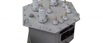
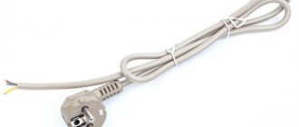
For assembly we will need: - a 220/16 160W transformer, that is, the secondary winding must have at least 16 volts without load and 10A maximum current. The current can be less (since the battery is charged at 0.1 of the rated current, a 60A/h battery will require a current of 6A) - a dimmer for electric lighting in an apartment or a table lamp. If only the power was right. Personally, I chose this one:
- diode bridge. You can use a diode bridge from the generator of any car, or you can buy 4 diodes designed for the required current on the radio market and assemble them according to the diagram:
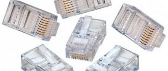
- voltammeter. The easiest way in my opinion. You can order the device on AliExpress here. It looks like this:
Everything in one case - a voltmeter and an ammeter. The device supply voltage is 4.5 - 30V, measures current up to 10A. Or you can install two pointer or digital instruments, a voltmeter and an ammeter, respectively.
- case, capacitor of at least 2200 µF * 25V, switch, 220V fuse, 16V fuse.
The charger is essentially a powerful power supply that has a 220V input, and the output is regulated from
0 to the current and voltage we need. How will we regulate this very current, because it is quite large. Some power supplies are built on thyristor or triac regulators (as well as field switches) to regulate the secondary current. Therefore, these chargers are expensive because... Powerful thyristors are already expensive, but you still need to assemble a control circuit for them. Chargers based on pulse voltage converters are also often used. It’s also not the cheapest and not the easiest option. I propose to regulate the primary current on the transformer using a ready-made voltage regulator (dimmer). And the current on the secondary winding directly depends on the current on the primary winding. Only knowing Ohm's law, the current in the primary winding will differ significantly from the secondary (it will be much less). And for a small current, smaller parts are needed, and therefore cheaper (this is why dimmers, although built on a triac, are very cheap).
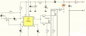
Schematic diagram of the device:
If the dimmer has a switch, then the SA switch is not needed in the diagram. It is also necessary to install a 16V fuse on the wire or in the housing to protect against output short circuit.
It is also necessary to trust and calibrate the device against an exemplary one (tseshka (multimeter) to help). It is calibrated using two regulators on the back of the board (VR - voltage and IR - current)
Transformer dimmers are a device that is used to regulate artificial lighting. The work flag concerns not only turning it on and off, but also setting brightness and power. In this case, the indicators are set depending on the needs of the person; you can set the option of light dimming, which will require minimal power, or bright, saturated light, which will allow you to see all the non-structural parts of the mechanism.
Lada 2109 In white slippers › Logbook › Charger - simple and cheap!
I decided to write my own method on how to assemble a battery charger.
I’ll say right away that the charger works exclusively in manual mode and does not damage the battery at all if you monitor the voltage and current. For assembly we will need: - a 220/16 160W transformer, that is, the secondary winding must have at least 16 volts without load and 10A maximum current. The current can be less (since the battery is charged at 0.1 of the rated current, a 60A/h battery will require a current of 6A) - a dimmer for electric lighting in an apartment or a table lamp. If only the power was right. Personally, I chose this one:
- diode bridge. You can use a diode bridge from the generator of any car, or you can buy 4 diodes designed for the required current on the radio market and assemble them according to the diagram:
- voltammeter. The easiest way in my opinion. You can order the device on AliExpress here. It looks like this:
Everything in one case - a voltmeter and an ammeter. The device supply voltage is 4.5 - 30V, measures current up to 10A. Or you can install two pointer or digital instruments, a voltmeter and an ammeter, respectively.
- case, capacitor of at least 2200 µF * 25V, switch, 220V fuse, 16V fuse.
The charger is essentially a powerful power supply that has a 220V input, and the output is regulated from
0 to the current and voltage we need. How will we regulate this very current, because it is quite large. Some power supplies are built on thyristor or triac regulators (as well as field switches) to regulate the secondary current. Therefore, these chargers are expensive because... Powerful thyristors are already expensive, but you still need to assemble a control circuit for them. Chargers based on pulse voltage converters are also often used. It’s also not the cheapest and not the easiest option. I propose to regulate the primary current on the transformer using a ready-made voltage regulator (dimmer). And the current on the secondary winding directly depends on the current on the primary winding. Only knowing Ohm's law, the current in the primary winding will differ significantly from the secondary (it will be much less). And for a small current, smaller parts are needed, and therefore cheaper (this is why dimmers, although built on a triac, are very cheap).
Schematic diagram of the device:
If the dimmer has a switch, then the SA switch is not needed in the diagram. It is also necessary to install a 16V fuse on the wire or in the housing to protect against output short circuit.
It is also necessary to trust and calibrate the device against an exemplary one (tseshka (multimeter) to help). It is calibrated using two regulators on the back of the board (VR - voltage and IR - current)
Source
Diagram and purpose of a thyristor voltage regulator for a transformer
The current flowing through the battery during charging is determined by the internal resistance of the battery, its emf and the voltage at the output of the charger. To change it, in addition to other methods, you can adjust the voltage on the primary winding. The most convenient way is to use a thyristor regulator.
Battery charging models
Chargers are divided into three groups:
- Launchers. Designed to start the engine with a discharged battery. It is not recommended to use it to charge batteries - insufficient voltage and lack of adjustments.
- Chargers. Designed to charge batteries. They have manual or automatic adjustment.
- Starting chargers. Can perform both functions.
Charger on dimmer
Sometimes a radio amateur on the farm needs a simple adjustable source for testing and tuning some equipment, as well as charging batteries that are not capricious to the regime.
A laboratory autotransformer, LATR, which allows you to regulate the input voltage from zero to maximum, is quite suitable for this purpose.
You can purchase an LATR, connect a ready-made rectifier to its output, in the form of a diode bridge and a capacitor, and if a low level of ripple is required, then add a smoothing LC filter.
However, such a source has some disadvantages:
The first drawback can be eliminated by adding an additional transformer isolating from the network, which will lead to an increase in the second drawback.
Somehow I was interested in welding current regulator circuits online and came across this circuit:
The diagram shows that a powerful welding transformer is regulated along the primary winding by counter-connected powerful thyristors VS1, VS2, which form an analogue of a triac. The regulator does not disrupt the operation of the transformer; the variable resistor R7 regulates the opening delay of the thyristors relative to the beginning of the half-cycle of the mains voltage, due to which the adjustment occurs.
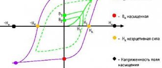
This is what the current shape looks like in the primary winding of the transformer:
The regulator circuit can be simplified, while the number of circuit components is reduced:
You can make such a regulator yourself, or you can purchase a ready-made one, since the circuit is identical to commercially available regulators for incandescent lamps - dimmers.
Photo of the dimmer itself:
Let's take a 250W network step-down transformer and assemble a circuit.
It remains to supplement the circuit with a simple rectifier and we get this simple but universal device:
The result was a classic, simple power supply with a function for adjusting the output voltage. This unit can be used to power and configure various designs, as well as to charge car batteries.
In order not to miss the latest updates in the workshop, subscribe to updates on VKontakte or Odnoklassniki, you can also subscribe to updates by email in the column on the right
Don’t want to delve into the routine of radio electronics? I recommend paying attention to the proposals of our Chinese friends. For a very reasonable price you can purchase quite high-quality chargers
A simple charger with an LED charging indicator, green battery is charging, red battery is charged.
There is short circuit protection and reverse polarity protection. Perfect for charging Moto batteries with a capacity of up to 20A/h; a 9A/h battery will charge in 7 hours, 20A/h in 16 hours. The price for this charger is only 403 rubles, delivery is free
Charger for a wide variety of 12-24V battery types with current up to 10A and peak current 12A. Able to charge Helium batteries and SA\SA. The charging technology is the same as the previous one in three stages. The charger is capable of charging both automatically and manually. The panel has an LCD indicator indicating voltage, charging current and charging percentage.
A good device if you need to charge all possible types of batteries of any capacity, up to 150Ah
The price for this miracle is 1,625 rubles, delivery is free. At the time of writing these lines, the number of orders is 23, rating 4.7 out of 5. When ordering, do not forget to indicate the Eurofork
Features of regulators for primary transformers
The battery charging current is 10% of its capacity. This means that a battery with a capacity of 60Ah is charged with a current of no more than 6A. The charging voltage when the car is running is 14.5V. Given the required margin, the charger should be capable of delivering 10A at 16V.
A voltage reserve is necessary to regulate and limit the charging current.
In different models of devices it is done in different ways:
- Additional resistances. They turn on after the diode bridge. The simplest design, but with the largest dimensions.
- Transistors. High adjustment accuracy, but the most complex circuit that requires good cooling of power transistors.
- Thyristor control. Simple diagrams. The adjustment is carried out by a thyristor switch in the primary winding circuit or by thyristors installed instead of diodes in the rectifier bridge.
What will you need for work?
A dimmer is a brightness control that allows you to turn a knob or press a key to change the intensity of light in a room.
According to the type of glow power adjustment, they are:
The first option is the simplest, but it cannot be called economical, since reducing the brightness of the glow does not change the load power. The other two are much more effective, but also have a more complex design. Depending on the principle of operation, what parts the dimmer includes will depend. In order not to be distracted from work, it is better to stock up on everything you need in advance.
For the examples below, you will need the following electronic elements:
Depending on the specific circuit and design of the dimmer, the set of necessary parts will also depend; you do not need to purchase all of the above. Note that some of them can be desoldered from old televisions, radios and other household appliances that you no longer use. Next, let's look at examples of specific schemes.
Professional equipment
Here are the characteristic distinctive features of a quality instrument:
- wires with silicone insulation, they have good flexibility and heat resistance;
- the holder and plug must have flexible sealed inputs; thanks to this design, the wires will not break out of them, even if an accidental jerk is allowed;
- the holders have a rubberized coating and are equipped with special protrusions for easy grip with your fingers;
- the electrode needles (and often the plugs) are equipped with special removable caps. This type of protection has two functions: it prevents contamination of the contact surface and significantly reduces the risk of getting a puncture injury;
- anodized or gold-plated electrodes;
- small internal resistance of the wire (ideally about 0.04 Ohm).
Products from the following brands meet these requirements: Fluke, Unitrend, Mastech, etc.
Figure 4. Flucke styli complete with crocodile clips
As a rule, good professional probes are collapsible, which allows you to use special attachments for them. It makes sense to talk about them in more detail.
On a triac
Such a dimmer will operate directly from a 220V mains voltage; the circuit is relatively simple, so even a novice radio amateur can assemble it. The principle of voltage regulation in this dimmer is to cut off a certain half-cycle of a sinusoid, due to which a decrease in the electrical parameter leads to real energy savings.
Look at the connection diagram, a triac is an electronic switch that is controlled by signals from a dinistor connected to the time-setting R - C chain.
Triac dimmer circuit
The operation of the circuit is as follows: after connecting the 220V phase to the dimmer, voltage will be applied to the timing chain C1 – R1 – R2, since the dinistor VS1 is closed, the current flows only through the capacitor and resistors.
Depending on the ohmic resistance set by the rotary resistor, the current value will also depend. The charging rate of capacitor C1 also depends on the current value; when the required potential value is reached, the dinistor will open.
Through the circuit of the opened dinistor, an opening signal is sent to triac VS2, and a switch is activated, passing a certain part of the half-cycle to the load. There is no holding current in the triac, therefore, with the discharge of the capacitor, the entire circuit returns to its original state until the next half-cycle, which opens the switch and applies potential to the load.
Change of sine wave
As you can see, such a dimmer circuit adjusts the brightness by “cutting” the shape of the sine wave to a certain pulse, reducing both the voltage and its effective value. Due to the unstable fluctuation of the curve, this dimmer model can definitely be connected to incandescent lamps, since they are not sensitive to the voltage waveform. As for LED and fluorescent models, they need to be tested on a ready-made dimmer.
To make such a dimmer for practical use, it is better to take a printed circuit board. Since with a stationary installation, when regulating the voltage, you will need a rigid attachment to the structure. You can either order it or make it yourself.
The assembly process consists of the following steps:
If you have marked mounting areas, adhere to these markings.
A little promised theory
Capacitance is directly proportional to the area of the conductors and inversely proportional to the distance between them. There is still a coefficient there, but for us it is not important now.
We have two conductors. Central core and wire screen. The distance between them is determined by the diameter of the wire. It is not possible to reduce the screen area much. No need to. It remains to reduce the SURFACE AREA OF THE CENTRAL VEIN.
Those. reduce its diameter as far as technically feasible without loss of mechanical strength.
Well, in order to increase this same strength while reducing the diameter, you need to choose a stronger material.
The wire can be represented like this:
Distributed capacitance along the length of the wire. Well, the greater the resistivity of the material of the central core, the less influence neighboring areas (adjacent containers) will have on each other. Therefore, a wire with high resistivity is advisable. For the same reason, it is not advisable to make the probe wire too long.
I won't look at the connectors. I’ll just say that I think BNC connectors are optimal for an oscilloscope. They are most often used. I would not recommend using a minijack or audio jack (although I use it myself, due to the fact that I do not use an oscilloscope in circuits with significant voltages). He's dangerous. The wire was pulled while testing circuits with good voltage. What happens next? And then the minijack, sliding along the socket, can cause a short circuit. And even if, for various reasons, nothing happened, this voltage will be present on the minijack itself. What if he falls into your lap? And there is an open central contact and the ground is nearby.
It's summer, it's hot, do you like to work in shorts? Choose BNC (no advertising). That's what's good about BNC. You can't just pull it out. And even if it happened, it is closed. Nothing dangerous should happen; what you wear will not be harmed))
Additional information can be gleaned from the series of articles Input nodes of homemade oscilloscopes. So, we got tired of the theory, now
On thyristors
This model of a thyristor dimmer is identical in principle to the previous version, but instead of a triac, thyristors act as a key. Due to the characteristics of the thyristor, it is more expedient to install such an electronic device for each half-wave of the voltage sinusoid.
An example of such a dimmer circuit is shown in the figure below:
Thyristor regulator circuit
Let's start analyzing the operation of the circuit with the positive half-cycle of the voltage curve - capacitor C1 is charged through a circuit of current-limiting resistors R3 - R4 - R5. When the charge reaches the threshold value for dinistor V3, it opens and supplies a control pulse to thyristor V1. In switch mode, V1 begins to pass voltage to the load, producing a certain portion of the voltage curve.
With a negative half-cycle of the sinusoid V1 is locked, no current will flow through it, and a charge will be supplied to the capacitor C2 through the current-setting circuit R1 - R2 - R5, which will eventually open the dinistor V4. Current will flow through it to the control electrode of thyristor V2; after the transistor opens, the same part of the half-cycle of the sine wave will flow to the load, but with the opposite sign.
Such a luminous flux power regulator can be used not only to change the brightness of lamp illumination, but also to control the heating temperature of a soldering iron and other devices.
Beginner's oscilloscope DSO138 - instructions and upgrades
Any beginner involved in radio electronics sooner or later is faced with the need to find out the signal shape and frequency. This is why there are oscilloscopes, or “donkeys” in common parlance. Therefore, today I propose to consider an inexpensive Chinese version - dso138, just right for a beginner.
Link
Initially, this model was developed as a DIY soldering kit, but Chinese friends realized that in a soldered form the demand for an oscilloscope is higher. We will consider a ready-made, working board.
Despite the fact that sellers claim a maximum testable frequency of 200 kHz, you can hardly count on such a range. Well, just to estimate approximately the frequency, without a real picture of the signal shape.
If we are realistic, we should expect a relatively passable picture at a frequency of 50 kHz; higher, there will be severe distortion. This will be enough to set up various switching power supplies.
An important point is that this oscilloscope can and should even be made portable. A pocket device, even with such low characteristics, can be a very useful assistant in the repair of low-frequency components.
So, upon purchase you receive a box with a board and display, a probe in the form of two crocodiles and “short” instructions in English. You have to figure out how to use various functions using the “highly scientific poke” method and minimal information from the Internet.
Catering
Power supply requires a 9 V source; according to manufacturers, the supply voltage can be in the range of 8-12 volts. The current consumption is not indicated, looking ahead - it is just over 100 mA.
I consider it a very practical and universal solution to power the board from a portable battery (power bank) - now almost everyone has them. In addition, by adapting the oscilloscope for a 5 V battery, the board can be powered from a telephone charger.
To increase the voltage from 5 to 9 volts, you can use a DC-DC converter, for example MT3608
- costs a penny in a radio store or from the same Chinese. To connect to the board, I used a computer fan connector - those with two wires, for example from an old video card, are suitable.
Either because of the input capacitor, or for other reasons, the board has large starting currents and when the entire circuit is turned on, the internal battery protection is triggered (2 A output). The problem is easily solved by adding a 0.5 Ohm resistor across the input power supply of the DC converter.
Before connecting the oscilloscope board, you need to set the voltage on the converter to 9-10 volts, this is done by rotating the trimming resistor.
Before turning it on for the first time, I recommend soldering a jumper or pin for a reference signal; the place for the jumper is located next to the power connectors. The internal generator produces rectangular pulses with a frequency of 1 kHz and an amplitude of 3.3 V. To check, you need to touch the red crocodile to the jumper; the black crocodile does not need to be hooked anywhere.
Now you can turn on the entire circuit and begin to master the simple instructions.
Instructions for use
Purpose of buttons and switches
. The board has 3 switches: input switching, sensitivity and its multiplier. The input switches to 3 positions: ❶ “GND” - the input is shorted to ground and the screen displays only its own noise, you can judge the deviation from zero of the factory settings.
Ideally, the line should be at zero, but there are deviations at different sensitivities. ❷ “AC” - The input reacts only to alternating and pulsating currents; when a constant voltage is applied to the probe, the beam only twitches a little. It will not be possible to measure DC voltage.
❸"DC" - The input is connected without an isolation capacitor, therefore it responds to both alternating voltage and direct voltage. Can be used as a millivoltmeter.
Sensitivity 1V; 0.1V; 10mV; within small limits it is regulated by X1 multipliers; X2; X5; The product of sensitivity and multiplier is one vertical cell on the screen. This value is displayed on the screen.
There are 4 buttons to the right of the screen (1 at the bottom doesn’t count - it’s a reboot): pause/start - allows you to stop the changing picture and look at it in more detail, parameter selection - allows you to select one of several parameters and use the +- buttons to adjust.
Selectable parameters (according to the chronology of clicks): ❶ The horizontal duration of one cell, in fact, is adjusted to the desired frequency; ❷ Playback mode, I didn’t notice much difference between the three modes, only minor nuances, the “AUTO” mode is the most convenient; ❸ Trigger trigger, on the edge or fall of the signal.
I don’t really understand this function, it’s related to setting up devices with a digital, logical signal; ❹ Trigger cursor, you can set the desired voltage value to trigger. When the signal curve reaches the set value, the LED under the screen is activated.
In addition, when the cursor is within the current signal, the graph is more convenient to view; it does not float. For analog measurements it is better to set it to zero; ❺ Scroll the picture left/right.
The function is useful when pausing - you can view a signal curve of a longer duration than the screen allows; ❻ Zero cursor; in fact, it can be moved both up and down. In this way, positive or negative half-waves can be examined in more detail;
As for the parameters of the measured signal in the working area of the screen, let’s figure out what they mean: Freq
— the signal frequency itself;
Cycl
— period time;
Pw
—half-cycle time;
Duty
- duty cycle (Western analogue of duty cycle, 50% is equal to duty cycle 2);
Vmax
— Maximum amplitude value of the signal;
Vmin
— Minimum amplitude value (maximum negative);
Vavr
- Average voltage;
Vpp
- Value from Vmin to Vmax, if the swing is from -5 V to +5 V, then this value is 10 V;
Vrms
— Mean square voltage;
Zero setting
. When you turn it on for the first time, it is very noticeable that the zero cursor does not coincide with the signal line. This discrepancy manifests itself differently at different positions of sensitivity and multipliers.
To adjust the beam, you need to use the “Parameter Selection” button to select the zero cursor, and then hold down the “Pause/Start” button for 2 seconds. Similarly, the trigger cursor is set to the same level as zero.
If you don't need the signal values on the screen
— use the “Parameter Selection” button to select the sweep duration and press “Pause/Start” for 2 seconds. Identically, the inscriptions return to the screen.
The most important thing: do not forget that the maximum input voltage on the oscilloscope probes should not exceed 50 V. To measure higher voltages, you need to build an additional divider or take another probe with a built-in divider.
We will definitely look at a homemade divider and a housing for the described board, but later. Now let’s touch a little on the practical part, namely, what benefits can this “toy” bring?
Practical use
This device can be used perfectly as a voltmeter and millivoltmeter of both direct and alternating voltage. Moreover, we are no longer limited as much by the frequency or shape of the signal as when using a multimeter.
When taking measurements, you should pay more attention not to amplitude values, but to root-mean-square Vrms.
It is the rms value that is taken into account when measuring alternating voltage - in the network, the amplitude values reach more than 310 V, but the effective value is exactly 220 (rms).
Since we can measure voltage with fairly high accuracy, we can therefore more accurately measure any currents on the shunt; for this we just need to learn how to use Ohm’s law.
An oscilloscope can perfectly look at audio signals - for such purposes it is not a toy. If the quality is tolerable, you can watch processes in switching power supplies. I purchased this board specifically for these purposes.
As an example: an oscilloscope helped me set up a screwdriver power supply (there is a description in this section) with powerful IGBT transistors.
I couldn’t understand why the unit didn’t want to start, I rewound the commutating transformer with different data - nothing.
When I evaluated the signals on the gates, everything became clear - there is not enough opening voltage, we need to add turns in the gate windings. Here is this damped signal, quite clear, frequency 44 kHz:
This concludes the publication. If this topic is at all interesting to site visitors, I will definitely expand and supplement it. Give ratings and be active.
Rate this publication:
4.6 (103 )
See also other articles
Share: Facebook
- Previous postHow to make a manual jigsaw with your own hands
- Next entryDo-it-yourself modernization of a gas boiler
No comments yet
Using capacitors
Such a dimmer operates only as a switch that changes the path of current flow supplying the load. But the push-button dimmer circuit is quite simple and does not require any specific elements.
Capacitor dimmer circuit
The principle of its operation is to move switch SA1 to one of three possible positions:
Depending on the parameters of the resistor and capacitive element, the voltage and brightness of the glow will depend. This dimmer is used to regulate lighting by dissipating some of the power in the R – C circuit, so you will not get any savings from the reduction.
Schematic diagrams of probes
Actually, the probe circuit that I used is extremely simple:
This is a divider by 10 for an oscilloscope with a 1 meg input impedance. It is better to make up several resistors connected in series. The switch simply closes the additional resistance directly. A tuning capacitor allows you to match the probe with a specific device.
Perhaps here is a more correct scheme that would be worth recommending:
It is clearly better in terms of permissible voltage, since the breakdown voltage of SMD resistors and capacitors is usually taken as 100 volts. I've come across claims that they can withstand 200-250 volts. Didn't check. But if you are examining fairly high-voltage circuits, you should use just such a circuit.
I have never done it, so I can’t give any recommendations for setting it up (selecting capacitors C2, C3, C4).
On the chip
In a dimmer assembled on a microcircuit, a change in voltage occurs for 12V consumers - LED strips, fluorescent lamps and other equipment. One of the circuit options is shown in the figure below.
Dimmer circuit on a chip
As you can see, control can be carried out both by a sensor connected to pin 2 and by an adjustable resistor VR1.
The microcircuit from pin 3 outputs a control signal through resistance R2 to the base of transistor VT1. By changing the voltage value with variable resistor VR1, the potential level at output 3 of the microcircuit changes, which increases or decreases the throughput of the transistor. At the same time, the brightness of the LEDs also changes if the control is carried out by LED lamps.
Wire selection
The selection of wire deserves special mention. The correct wire looks like this:
The 3.5 mm minijack is located nearby for scale
The correct wire is a more or less ordinary shielded wire, with one significant difference - it has one central core. Very thin and made of steel wire, or even wire with high resistivity. I’ll explain why a little later.
This type of wire is not very common and is quite difficult to find. In principle, if you do not work with high frequencies of the order of ten megahertz, you may not feel much of a difference using a regular shielded wire. I have come across the opinion that at frequencies below 3-5 MHz the choice of wire is not critical. I can neither confirm nor deny - there is no practice at frequencies above 1 MHz. I will also tell you later in what cases this may have an effect.
Homemade oscilloscopes don't often have multi-megahertz bandwidth, so use whatever wire you can find. Just try to choose one with thinner central cores and fewer of them. I have come across the opinion that the central core should be thicker, but this is clearly part of the series of “bad advice”. Low resistance to the oscilloscope wire is unnecessary. There currents are in nanoamperes.
And it is important to understand that the lower the intrinsic capacity of the manufactured probe, the better. This is due to the fact that when you connect the probe to the device under test, you are thereby connecting additional capacitance.
If you connect directly to the output of a logical element or to a UPS, i.e. to a sufficiently powerful signal source that has a sufficiently low intrinsic resistance, then everything will be displayed normally. But if there is significant resistance in the circuit, then the probe capacitance will greatly distort the signal shape, because will charge through this resistance. This means that you will no longer be sure of the reliability of the oscillogram. Those. The lower the probe's intrinsic capacitance, the wider the range of possible uses for your oscilloscope.
What are dimmers and where are they used?
A dimmer is a mechanism used in a similar way to a conventional mechanical switch. But unlike a standard device, the device is able to smoothly regulate the power and brightness of artificial lighting. The device is miniature and can be installed either as a single copy, isolated, or in a box.
The first dimmer was invented by the American Granville Woods. Industrial companies immediately liked his innovation. They adopted complete equipment and began to equip various devices with it. Interestingly, the first dimmers became common lighting devices for theaters - they made it possible to create the effect of receding light and darken the stage.
Dimmers are equipped with a number of useful functions that other devices with a similar range of actions often cannot provide.
First of all, it is adjusting the lighting. The mechanical switch is sharp and there is no dimming effect. But there are also other useful functional features:
Modern dimmers are often connected to a smart home system. This allows you to create optimal and natural lighting in the rooms. It also provides a security function: you can turn on the light from your smartphone when you are not at home and the like.
The scope of application of the device is large-scale. For example, modular variations are used to illuminate corridors and staircases. Dimmers in a box allow you to adjust the operation of lighting systems in your home or office. The monoblock version is used if a standard switch is not installed due to insufficient wall width.
The wide scope of application is determined by the ability to change the mode in accordance with your needs. Also, the device, when operating at medium power, shows significant energy savings, but at the same time an excellent efficiency.
Homemade oscilloscope probe
Homemade oscilloscopes are no longer a rarity as microcontrollers develop. And naturally the need for a probe for it arises. Preferably with a built-in divider. Some of the possible designs are discussed in this article.
The probe is assembled on a piece of foil fiberglass and placed in a metal tube that acts as a screen. In order not to cause emergency situations when and if the probe falls on the switched-on device under test, the tube is covered with heat shrink. Without coating, the workpiece looks like this:
Disassembled probe:
Designs may vary. Just need to consider some things:
- If you perform a probe without a divider, i.e. it does not contain large resistances and switches, i.e. elements subject to electromagnetic interference, it is advisable to stretch the shielded probe wire all the way to the needle. In this case, you will not need additional shielding of the elements and the probe can be made from any dielectric. For example, use one of the tester probes.
- If the probe has a divider, then when you pick it up, you will inevitably increase interference and interference. Those. shielding of the divider elements will be required.
In my case, the connection of the tube to the screen (more precisely, to the back side of the fiberglass laminate) is made by soldering a spring onto the tectolite, which creates contact between the screen and the probe board.
As a needle I used a “Dad” from a ShR type connector. But it can be made from any other suitable rod. The connector from the ShR is convenient in that its “Mother” can be soldered into a clamp, which can be put on the probe if necessary.
Wire selection
The selection of wire deserves special mention. The correct wire looks like this:
The 3.5 mm minijack is located nearby for scale
The correct wire is a more or less ordinary shielded wire, with one significant difference - it has one central core. Very thin and made of steel wire, or even wire with high resistivity. I’ll explain why a little later.
This type of wire is not very common and is quite difficult to find.
In principle, if you do not work with high frequencies of the order of ten megahertz, you may not feel much of a difference using a regular shielded wire.
I have come across the opinion that at frequencies below 3-5 MHz the choice of wire is not critical. I can neither confirm nor deny - there is no practice at frequencies above 1 MHz. I will also tell you later in what cases this may have an effect.
Homemade oscilloscopes don't often have multi-megahertz bandwidth, so use whatever wire you can find.
Just try to choose one with thinner central cores and fewer of them. I have come across the opinion that the central core should be thicker, but this is clearly part of the series of “bad advice”.
Low resistance to the oscilloscope wire is unnecessary. There currents are in nanoamperes.
And it is important to understand that the lower the intrinsic capacity of the manufactured probe, the better. This is due to the fact that when you connect the probe to the device under test, you are thereby connecting additional capacitance.
If you connect directly to the output of a logical element or to a UPS, i.e. to a sufficiently powerful signal source that has a sufficiently low intrinsic resistance, then everything will be displayed normally.
But if there is significant resistance in the circuit, then the probe capacitance will greatly distort the signal shape, because will charge through this resistance. This means that you will no longer be sure of the reliability of the oscillogram. Those.
The lower the probe's intrinsic capacitance, the wider the range of possible uses for your oscilloscope.
Read more: Where is the wiper relay accent located?
Schematic diagrams of probes
Actually, the probe circuit that I used is extremely simple:
This is a divider by 10 for an oscilloscope with a 1 meg input impedance. It is better to make up several resistors connected in series. The switch simply closes the additional resistance directly. A tuning capacitor allows you to match the probe with a specific device.
Perhaps here is a more correct scheme that would be worth recommending:
It is clearly better in terms of permissible voltage, since the breakdown voltage of SMD resistors and capacitors is usually taken as 100 volts. I've come across claims that they can withstand 200-250 volts. Didn't check. But if you are examining fairly high-voltage circuits, you should use just such a circuit.
I have never done it, so I can’t give any recommendations for setting it up (selecting capacitors C2, C3, C4).
A little promised theory
Capacitance is directly proportional to the area of the conductors and inversely proportional to the distance between them. There is still a coefficient there, but for us it is not important now.
We have two conductors. Central core and wire screen. The distance between them is determined by the diameter of the wire. It is not possible to reduce the screen area much. No need to. It remains to reduce the SURFACE AREA OF THE CENTRAL VEIN.
Those. reduce its diameter as far as technically feasible without loss of mechanical strength.
Well, in order to increase this same strength while reducing the diameter, you need to choose a stronger material.
The wire can be represented like this:
Distributed capacitance along the length of the wire. Well, the greater the resistivity of the material of the central core, the less influence neighboring areas (adjacent containers) will have on each other. Therefore, a wire with high resistivity is advisable. For the same reason, it is not advisable to make the probe wire too long.
https://www.youtube.com/watch?v=ZEqY1dNFeBc
I won't look at the connectors. I’ll just say that I think BNC connectors are optimal for an oscilloscope. They are most often used. I would not recommend using a minijack or audio jack (although I use it myself, due to the fact that I do not use an oscilloscope in circuits with significant voltages). He's dangerous.
The wire was pulled while testing circuits with good voltage. What happens next? And then the minijack, sliding along the socket, can cause a short circuit. And even if, for various reasons, nothing happened, this voltage will be present on the minijack itself.
What if he falls into your lap? And there is an open central contact and the ground is nearby.
It's summer, it's hot, do you like to work in shorts? Choose BNC (no advertising). That's what's good about BNC. You can't just pull it out. And even if it happened, it is closed. Nothing dangerous should happen; what you wear will not be harmed))
Additional information can be gleaned from the series of articles Input nodes of homemade oscilloscopes. So, we got tired of the theory, now
Probe No. 2
The good thing about it is that it can be inserted like this:
Read more: Kia Sorento Prime 2022 new body reviews
Or like this, he doesn’t care, he spins freely.
It's structured something like this:
The only thing that will still be done on it. The hole for the ground wire to exit from the probe will be filled with a drop of hot-melt adhesive to make it more difficult to pull it out during an accidental tug, and the wire will be fixed in the handle with a piece of a match sharpened to a flat wedge.
So as not to break or unscrew the central core. By the way, this is the easiest way to “treat” cheap Chinese tester probes so that the wire does not break off from the tip.
What you should pay attention to: The screen extends almost to the tip. There should not be a significant open area of the central core under your fingers, otherwise you will admire the hand guidance on the donkey’s display.
Especially for the Radioschema website - Trishin A.O. Komsomolsk-on-Amur. August 2022
Discuss the article HOMEMADE PROBE FOR AN OSCILLOSCOPE
- Schematic and PCB
- Installation and Calibration Recommendations
- Probe with divider and opto-isolator - diagram
The circuit of a probe for an oscilloscope with a divider, which we will propose to assemble today, is simple. If you find the specified microcircuits, installation will take only a couple of days
Oscilloscope probe with divider - circuit and printed circuit board
Among the advantages of the circuit, we note complete galvanic isolation up to 3 kV. The disadvantage is the low frequency of signals that can be examined without distortion. For a rectangle, 20 kHz will be the limit. If configured with some phase shift, then the sine can be viewed at about 50 kHz.
Thus, this device is perfect for energy engineers. Of course, not in the laboratory, but in operational diagnostics of high-voltage lines.
Oscilloscope Probe Circuit Board:
Do-it-yourself oscilloscope probe - recommendations for installation and calibration
The basis of the design is the galvanically isolated ACPL-790 amplifier. Hence the main limitation on the frequencies of the probe. The amplifier is powered by an isolated voltage converter. The input signal (maximum 300 mV) is taken from the resistor voltage divider.
The presented example is designed for 2.5 kV DC input. The AD620 has a slew rate of the signal at the output of the microcircuit of 0.3 V/µs.
The measurement amplifier is also powered by a converter providing a bipolar voltage of ±5 V. There are 20 resistors in 2 stripes at the input. At high voltages, they will release a lot of power, at 2.5 kV about 3 W.
The board measures 100x65mm and fits into a small plastic case. The production of the printed circuit board is Chinese (for a promotion, 10 pieces of 100×100 size are less than $10).
After assembly and testing, we cover the entire high-voltage part of the printed circuit board and parts with several layers of varnish. Power supply is from an external 24 volt power supply.
You can download the documentation for the microcircuits below.
Calibration: a regular 220 V network voltage and a high-quality digital multimeter were used. We adjust the trimmers until we get Vrms readings on the oscilloscope screen similar to those of the reference multimeter.
How to make a probe cable for a low-frequency virtual oscilloscope?
How to make a simple low-frequency probe cable for an oscilloscope. https://oldoctober.com/
It is advisable to make such a cable even if you have a set of professional cables.
Thanks to its thin, flexible wire and small dimensions, it can be a good alternative to bulky and inconvenient industrial cables.
Of course, the scope is limited to repairing audio equipment, but if you use a virtual oscilloscope based on an audio card, then a more serious cable may never be needed.
Read more: Is the yellow traffic light prohibiting or not?
Construction and details
A felt-tip pen or marker shell is suitable as a housing for the probe. Any shielded wire will also work, although it is better to choose a more elastic one.
The drawing shows a cross-section of the probe. https://oldoctober.com/
- The point is a gypsy needle.
- The protective tube is a cambric.
- Bushing – steel or brass.
- Locking screw – M3, steel.
- The body is the shell of the marker.
- The cable is shielded wire.
- The hole in the body is Ø3mm.
- Bushing – M3, brass.
- Common wire.
- Bracket – common wire fastening unit, brass.
- Washer – M3, steel.
- Clamp – brass.
- Locking screw – M3, steel.
- The hole in the plug is Ø3mm.
- The cap is the shell of the marker.
- The protective tube is a cambric.
The sleeve pos. 3 is glued into the hole in the marker shell. The diameter of the hole in the sleeve pos. 3 is slightly larger than the diameter of the needle.
The locking screw pos. 4 fixes the needle in the sleeve pos. 3.
The shielding braid of the cable is soldered to the sleeve pos. 12, and the central wire to the needle pos. 1.
The locking screw pos. 13 secures the cable in the bushing pos. 12.
The sleeve pos. 8 is screwed into the clamp pos. 12, having previously passed through the holes pos. 7, pos. 14 and the hole in the washer pos. 11. Thus, the bushing pos. 8 ensures the connection of all structural elements.
In this picture you can see what the insides of the probe look like in reality.
This is what happened.
Small details
The tip of the probe is made of a gypsy needle.
The most convenient and versatile tip shape is triangular.
The clamp pos. 12 is removed from the electrical terminal, which can be purchased at any hardware store.
That seems to be the whole description.
Types and design features of the device
All types of dimmers have identical features that make them popular. This is not only a change in brightness, but also equipped with dimming and flickering modes, the possibility of remote control, automatic shutdown, smooth results, miniature size and relative ease of assembly. As for the last point, a novice amateur can assemble a simple mechanism without any frills.
Types of dimmers for transformers are divided according to the type of control and the type of lamps used. Based on the first criterion, monoblocks and models are distinguished. Monoblock dimmers are similar in appearance to conventional switches.
The static format mechanism cannot move, and in most cases its scope of use is limited. Therefore, they began to produce mechanisms that could turn.
The so-called rotary dimmers are much more convenient, since turning them off and on is done by turning them, the design lasts longer and is easier to repair. There are push options, combined with rotary ones - turning on and off is controlled by a button (it is often a mechanism), and the level of illumination and dimming is adjusted by turning. The keyboard variations are unusual - in appearance they resemble a switch with two components.
The right side of the device is adapted to change the brightness of artificial lighting, and the left side is responsible for turning it off. There are also models that can be controlled remotely using a remote control. The device is convenient; transformers with dimmers of this type are among the modern variations. Touch mechanisms are becoming popular, which are regulated using switching sensors (the light level is set from certain positions).
In addition to monoblock ones, there are modular designs. They are located in the panel, adjustment occurs using a button located on the control panel. The operating instructions for the transformer indicate how long you need to hold this button and in what position to turn on a specific mode.
The second important characteristic after the control method is the lamps used. The use of various dimmers is determined by the variety of functioning devices and changing technical requirements for each.
For incandescent and halogen lamps
Options for incandescent lamps are the simplest designs. The principle of operation is that the voltage changes up or down. The values are set arbitrarily, but it is worth considering that as the voltage decreases, the spectrum of the glow changes. When the lamp is heated, a characteristic reddish tint appears that cannot be eliminated.
What is a triac
The thyristor has a drawback that complicates its use in an alternating current network - it passes through only one half-wave and the output produces a constant pulsating voltage instead of an alternating voltage. Therefore, these devices are used in pairs or together with a diode bridge. The triac is free from this drawback.
A triac is similar in appearance to a thyristor. Just like a thyristor, it opens with a current pulse flowing through the control electrode, but this device passes both half-waves through itself and is capable of operating in an alternating current network.
Schematic diagram of a triac current regulator for active and inductive loads. The design of a triac regulator is similar to a thyristor regulator. The difference is that the triac controls both polarities and therefore there is no need to use a diode bridge or back-to-back connection of elements.
In addition, the polarity of the control voltage does not matter for the triac, which simplifies the pulse control circuit.
Advice! To adjust the triac, you can use a dimmer from an incandescent lamp. To do this, it is connected between the anode and the control electrode of the power triac.
What transformers are used in conjunction with dimmers
Electronic transformers are widely used. It features smooth start-up, compact dimensions and minimal weight. Shows the voltage at the input of optimal parameters, the voltage supply is automatically controlled, and there is short circuit protection.
Special toroidal transformers are also used, which show a high level of reliability. Unlike electronic devices, they require constant power.
The mechanism of interaction between the dimmer and the transformer
How a dimmer works is easy to understand if you look closely at the constitutive features of the circular mechanism. According to the power supply scheme, it is important that it consumes minimal power and efficiency is high. Functional:
The user can regulate the voltage supply. He selects the indicators himself, smoothly moving the dimmer head. The connection is made through light bulbs in two places at the bottom of the structure.
Diagram and step-by-step instructions for connecting the device
At the first stage, preparatory actions are carried out: the power supply is turned off, the equipment is turned off. Gather the necessary tools - you will need an indicator screwdriver.
Next, the release button is removed and the box is removed, the mechanism is removed. The step-by-step algorithm after extraction is as follows:
The dimmer operating instructions indicate the connection sequence. But special attention should be paid to the phase wire, which is connected strictly to the external terminal.