To solve problems of controlled motion in modern precision systems, valve-type (brushless) motors are increasingly being used. This trend is due to the advantages of switch-type motors and the rapid development of the computing capabilities of microelectronics. As is known, valve-type (synchronous) motors provide the highest long-term torque density (torque per unit volume) and energy efficiency compared to any other type of motor.
A modern valve drive combines electrical, mechanical and electronic subsystems into a single, seamless mechatronic device. As part of this approach, it is possible to significantly reduce dimensions, get rid of unnecessary converters and intermediate elements, and therefore increase the reliability of the entire drive as a whole.
Within the framework of this article, the operating principle and structure of modern brushless motors are discussed, the principles of control of a valve converter for switching using rotor position sensors are described, and the features of the integrated design of brushless motors are listed.
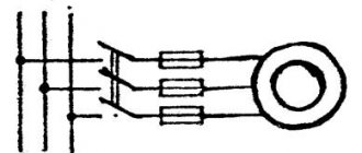
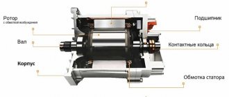
Switched motor diagram
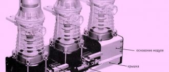
The engine consists of the following parts:
1. Back of the case. 2. Stator. 3. Bearing. 4. Magnetic disk (rotor). 5. Bearing. 6. Stator with winding. 7. Front part of the body.
The switch motor has an interconnection between the multiphase stator and rotor windings. They have permanent magnets and a built-in position sensor. Switching of the device is realized using a valve converter, which is why it got its name.
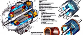
The switch motor circuit consists of a back cover and sensor circuit board, bearing bushing, shaft and bearing itself, rotor magnets, insulating ring, winding, triangular spring, intermediate bushing, Hall sensor, insulation, housing and wires.
In the case of a star connection of the windings, the device has large constant moments, so this assembly is used to control axes. If the windings are fastened in a triangle, they can be used to work at high speeds. Most often, the number of pole pairs is calculated by the number of rotor magnets, which help determine the ratio of electrical and mechanical revolutions.
The stator can be manufactured with an iron-free or iron core. Using such designs with the first option, it is possible to ensure that there is no attraction of the rotor magnets, but at the same time the engine efficiency is reduced by 20% due to a decrease in the constant torque value.
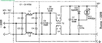
The diagram shows that in the stator the current is generated in the windings, and in the rotor it is created using high-energy permanent magnets. Legend: - VT1-VT7 - transistor communicators; — A, B, C – winding phases; — M – engine torque; — DR – rotor position sensor; — U – motor supply voltage regulator; — S (south), N (north) – direction of the magnet; — UZ – frequency converter; — BR – speed sensor; — VD – zener diode; — L – inductor.
The motor diagram shows that one of the main advantages of a rotor in which permanent magnets are installed is a reduction in its diameter and, as a result, a reduction in the moment of inertia. Such devices can be built into the device itself or located on its surface. A decrease in this indicator very often leads to small values of the balance of the moment of inertia of the motor itself and the load reduced to its shaft, which complicates the operation of the drive. For this reason, manufacturers can offer standard and 2-4 times increased moment of inertia.
Position sensors and additional devices
Hall sensors (digital or analogue), an encoder (digital, analogue or absolute) or a resolver can be used as the position sensor required for switching the switch motor.
Digital Hall sensors are used for the most common - trapezoidal commutation of a valve motor. Digital Hall sensors can also be implemented on the optical scale of the encoder. Analog Hall sensors are used for sinusoidal commutation of a valve motor.
The encoder has three differential channels - two channels A, B of rectangular pulses shifted by 90 electrical degrees, and a zero pulse I (index). The resolver is a rotating transformer with an excitation winding and two output windings shifted by 90 electrical degrees.
The analog encoder has analog sin/cos (1V peaktopeak) differential outputs.
An external interpolator allows you to increase the original resolution with a multiplication factor of up to 4096. The absolute encoder transmits position information via a synchronous serial interface (SSI or BiSS), the protocol of which is specified by the encoder manufacturer. Some of the most popular protocols are Heidenhain EnDat, Tamagawa Smart Abs and Stegman Hiperface protocols.
In addition to the position sensor, the following can be additionally built-in: a tachogenerator, a temperature sensor, a brake or a gearbox.
The tachogenerator is used when using a valve motor in speed control/stabilization mode with high accuracy.
The temperature sensor to protect the windings from overheating consists of several posistors connected in series, i.e. thermistors with positive temperature coefficient (PTC).
Work principles
Today, a valve motor is becoming very popular, the operating principle of which is based on the fact that the device controller begins to switch the stator windings. Due to this, the magnetic field vector always remains shifted by an angle approaching 900 (-900) relative to the rotor. The controller is designed to control the current that moves through the motor windings, including the magnitude of the stator magnetic field. Therefore, it is possible to regulate the torque that acts on the device. The angle between the vectors can determine the direction of rotation that is acting on it.
It must be taken into account that we are talking about electrical degrees (they are much smaller than geometric ones). As an example, we give a calculation of a rotor motor with a rotor that has 3 pairs of poles. Then its optimal angle will be 900/3=300. These pairs provide 6 phases of the commutation windings, then it turns out that the stator vector can move in jumps of 600. From this it is clear that the real angle between the vectors will necessarily vary from 600 to 1200, starting with the rotation of the rotor.
A valve motor, the operating principle of which is based on the rotation of the commutation phases, due to which the excitation flow is maintained by a relatively constant movement of the armature, after their interaction begins to generate a rotating torque. He rushes to turn the rotor in such a way that all the excitation and armature flows coincide together. But during its reversal, the sensor begins to switch the windings, and the flow moves to the next step. At this moment, the resulting vector will move, but will remain completely motionless compared to the rotor flux, which will ultimately create shaft torque.
Switching methods using a rotor position sensor
Switching methods for a rotary switch motor differ in the type of rotor position sensor and the features of current regulation in the phases of the stator windings.
3.1. Trapezoidal or six-step (sixstep) commutation of a valve motor is carried out using digital Hall sensors. For 3 Hall sensors, which are a “rough” rotor position sensor, there will be six possible states per full electrical revolution, each of which corresponds to 60 electrical degrees. For each permanent state of the Hall sensors, only two motor windings are connected, and the third is disconnected from the voltage source. Constancy of the current vector within ±30 electrical degrees from the optimal (creating maximum torque) leads to 17% current ripple.
Advantages:
- Ready for operation when power is turned on;
- cheap current amplifier;
- current (torque) control with an analog signal ±10V.
Flaws:
- current ripple;
- average performance during positioning and uniformity during scanning.
Scope of application: speed control with low requirements for efficiency and uniformity of movement at low speeds.
3.2. Sinusoidal commutation avoids the disadvantages of trapezoidal commutation due to continuous and smooth commutation of the current vector. This is achieved due to the higher resolution of the rotor position sensor (usually an incremental encoder) compared to digital Hall sensors which only have a resolution of 60 electrical degrees. For a standard motor with a star connection, it is enough to control the current in two windings using two regulators based on PIregulators. This switching method is very efficient at low and medium speeds, but has errors at high speeds. In this case, due to the limited gain of the PI controller at a given DC voltage (DC bus), the maximum speed is limited. The phase advance method allows you to slightly increase the speed.
Advantages:
- minimal current ripple;
- high performance during positioning and uniformity during scanning.
Flaws:
limiting the maximum speed at a given constant voltage;
current control (torque/force) using two analog signals ±10V.
Scope of application: precision mechanisms.
3.3. Direct vector control of current in DQ coordinates uses transformations between static DQ and rotating UVW current vector coordinates, known as Park-Clark transformations. Unlike the sinusoidal one, this switching method involves the operation of the PIregulator with DC voltages, and not sinusoidal voltages. This ensures the quality of current control, independent of the motor rotation speed.
Vector control involves regulation of the quadratic (D) and direct (Q) components of the current. Because Only the direct (Q) current component, perpendicular to the rotor field, creates motor torque, then the current command is supplied to the input of the direct (Q) current component. A “0” signal is supplied to the input of the square-law (D) current component.
Conversions between static DQ and rotating UVW coordinates of the current vector are made taking into account the phase currents and rotor position.
Vector control, with the advantages of sinusoidal commutation, allows you to expand the speed range of a brushless motor by making fuller use of the DC voltage.
It should be noted that for sinusoidal or vector current commutation when using an incremental (relative) rotor position sensor, it is necessary to initially (i.e., every time the power is turned on) phase the rotor position relative to the stator phases. The algorithm for such initial phasing is usually “built-in”.
Trapezoidal commutation of a brushless motor does not require initial phasing due to the use of Hall sensors, which are absolute rotor position sensors. Therefore, they are sometimes used in conjunction with an incremental position sensor to implement sinusoidal or vector current commutation without the need for initial phasing. This configuration is recommended for mechanisms where the implementation of the initial phasing procedure is difficult, for example, vertical movement mechanisms.
Advantages
When using a valve motor in operation, one can note the following advantages:
— possibility of using a wide range for modifying the rotation speed;
— high dynamics and speed;
— maximum positioning accuracy;
— low maintenance costs;
— the device can be classified as an explosion-proof facility;
— has the ability to withstand large overloads at the moment of rotation;
— high efficiency, which is more than 90%;
— there are sliding electronic contacts that significantly increase the working life and service life;
— during long-term operation there is no overheating of the electric motor.
Specifications
When choosing a specific model, it is important to determine its suitability for the installation location, so it is important to pay attention to the following characteristics of brushless motors:
- rated voltage - determines the supply value that must be supplied to the valve motor to obtain the rated force;
- power consumption - a characteristic of an electric motor, showing the amount of power consumed to operate the device;
- Efficiency - shows the ratio of useful work performed by a valve motor to the power consumed;
- shaft power - useful work of an electric machine performed due to traction force;
- rated frequency - determines the number of revolutions per minute that the valve motor can make in the nominal operating mode;
- frequency adjustment range – shows within what limits the shaft speed can be changed for a specific model;
- rated torque - determines the force created on the shaft of a switch-type motor at optimal operating parameters; the starting and maximum torque can also be regulated in the parameters;
- load factor - shows how much the efficiency of an electric machine decreases, depending on the rise above sea level;
- overall dimensions and weight of the valve motor.
Switched reluctance motor
A switched reluctance motor is a device that has a switching magnetic resistance. In it, energy conversion occurs due to changes in the inductance of the windings, which are located on pronounced stator teeth when the toothed magnetic rotor moves. The device receives power from an electrical converter, which alternately switches the motor windings according to the movement of the rotor.
A switched reluctance motor is a complex complex system in which components that are diverse in their physical nature work together. Successful design of such devices requires advanced knowledge of machine design and mechanics, as well as electronics, electromechanics and microprocessor technology.
The modern device acts as an electric motor operating in conjunction with an electronic converter, which is manufactured using integrated technology using a microprocessor. It allows for high-quality engine control with the best energy conversion performance.
Engine properties
Such devices have high dynamics, high overload capacity and precise positioning. Due to the fact that they have no moving parts, their use is possible in explosive aggressive environments. Such motors are also called brushless; their main advantage, compared to brushed motors, is the speed, which depends on the supply voltage of the loading torque. Also, another important property is the absence of abrasive and rubbing elements that switch contacts, due to which the service life of the device increases.
DC valve motors
All DC motors can be called brushless motors. They operate from a direct current network. The brush assembly is provided to electrically connect the rotor and stator circuits. This part is the most vulnerable and quite difficult to maintain and repair.
A DC valve motor operates on the same principle as all synchronous devices of this type. It is a closed system that includes a power semiconductor converter, a rotor position sensor and a coordinator.
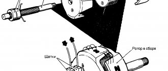
DIY brushless
@@The design features of CD-ROM engines are very different. Therefore, this article provides general recommendations for converting such engines at minimal cost into 3-phase aircraft model engines.
@@Requirements for CD-ROM engines (data are given for engines that were actually redesigned):
- The number of teeth (poles) of the rotor must be 9
- Number of newly installed magnets: 12
- Rotor diameter: 28.5 mm
- Rotor height: 7.8 mm
- Axle diameter: 3mm
- Axle length: 6.8mm
- Stator diameter: 24 mm
- Stator height: 5.2 mm
- Weight of the converted engine - 21 g
- Winding type - delta
- Winding with wire with a diameter of 0.4-0.5 (preferably PETV)
- Number of turns - 17-20 per tooth
@@Adhesives used: “111”, thread lockers (sold in auto stores). @@Epoxy resin used: any non-Russian or 5-minute resin.
Preparatory work
@@A magnetized plastic ring is glued to the inside of the rotor. Remove it carefully. This can be done as follows: a bent and heated nail is inserted into the plastic. Let it cool and carefully pull out the plastic ring
@@We disconnect the stator from the plate on which it is mounted (there are a lot of mounting options and therefore I do not present the technology - in each specific case, decide for yourself how to do this). Disconnect the stator, carefully remove the winding from it, trying not to damage the factory varnish.
Rewind
@@The stator is rewinded with a copper wire with a diameter of 0.4mm - 0.5mm. We wind from 17 to 20 turns on each pole.
@@The fewer turns, the higher the revolutions; more turns produce higher torque. The wire insulation must remain intact - this is critical, otherwise your engine will not work.
@@You can choose between delta and star winding types. With star winding, the motor will have higher torque, lower RPM and will "eat" less. Delta winding will produce a “hotter” motor with higher rpm and greater efficiency, but will have a greater “appetite” and will run hotter. Star winding is “heavier” for controller operation.
Quality checking
@@Checking the quality of winding is done with a multimeter. The wire MUST NOT be broken or have damaged insulation. The resistance of the windings should be approximately the same. The winding wires must not be short-circuited to each other or to the stator (in case of insulation damage). If you are not sure that there is no damage or shortness, remove the wound wire and rewind it again. Connect, secure and solder the winding terminals. Winding resistance ~ 0.1-0.14 ohms per phase.
Installing new magnets into the rotor
@@VERY IMPORTANT - The magnets must be installed with the correct polarity - NSNS...or your motor will not run. A good way to check polarity is to place 12 magnets on a table in a row and stick the magnets into the rotor shell in the same order. For gluing, use high quality glue (do not use epoxy resin for 5 minutes).
@@Achieve uniform placement of the magnets in the rotor shell. How you can do this: when installing magnets in a glass, line them with thin pieces of paper of the same thickness; if one of the gaps is larger, then increase the thickness of the paper. The distance between the magnets must be the same. Take the time to do this work. After installing the magnets and gluing them, fill the gaps between them with epoxy resin. Be careful not to overfill the resin.
Trial
@@There should be no friction between the rotor and magnets. If the movement when cranking is without significant force and jolts, then you can try to start the assembled engine.
@@YOU CAN change the direction of rotation by changing 2 of the 3 pins between the motor and the controller.
@@Ready motors.
Authors of published articles receive discounts in our store
Date: Tuesday, 08 October 2013
Synchronous and asynchronous DC motors are widely used in various areas of industrial production. In this article we will take a detailed look at their design and operating principle.
AC fan motors
Such devices receive their power from AC mains. The rotor rotation speed and the movement of the first harmonic of the stator magnetic force completely coincide. This subtype of engines can be used at high power. This group includes stepper and reluctance valves. A distinctive feature of stepper devices is the discrete angular displacement of the rotor during operation. The power supply to the windings is generated using semiconductor components. The valve motor is controlled by sequential displacement of the rotor, which creates a switching of its power from one winding to another. This device can be divided into single-phase, three-phase and multi-phase, the former of which may contain a starting winding or a phase-shifting circuit, and can also be manually started.
Control system
If the electromechanical part consists primarily of three components, including a rotor, a stator and a supporting structure in the form of a housing, then the control infrastructure is more segmented - the number of elements can reach several dozen. Another thing is that they can be divided into types. Only the inverter will be presented in the singular. It is responsible for switching functions, connecting and switching phases. The main tasks of control with the supply of signals are performed by sensors. The main one is the rotor position detector. In addition, a signal regulation system is also included in the control unit. This is a node with keys, through which the connection between sensors and electromechanical components is realized.
Information about the rotor position is processed by a microprocessor. Externally, the interface of this block is a control panel. At reception, it works with pulse width modulation signals (PWM signal). If the supply of low-voltage signals is provided, then a transistor bridge is also installed in the control unit. It converts the signal into power voltage, which is subsequently supplied to the electric motor. The presence of sensors with a pulse processing system is what distinguishes the control of a valve motor from the means of monitoring brush-commutator units. Another thing is that the possibility of introducing electronic equipment with sensors is also allowed in commutator machines along with mechanical control systems.
Operating principle of a synchronous motor
A valve synchronous motor operates based on the interaction of the magnetic fields of the rotor and stator. Schematically, the magnetic field during rotation can be represented by the pluses of the same magnets, which move at the speed of the stator magnetic field. The rotor field can also be depicted as a permanent magnet that rotates synchronously with the stator field. In the absence of external torque applied to the shaft of the device, the axes completely coincide. The influencing forces of attraction run along the entire axis of the poles and can compensate each other. The angle between them is equal to zero.
If a braking torque is applied to the machine shaft, the rotor moves to the side with a delay. Thanks to this, the attractive forces are divided into components, which are directed along the axis of the positive indicators and perpendicular to the axis of the poles. If an external moment is applied, which creates acceleration, that is, begins to act in the direction of rotation of the shaft, the picture of the interaction of fields will completely change to the opposite. The direction of the angular displacement begins to transform to the opposite, and in connection with this, the direction of the tangential forces and the effect of the electromagnetic moment change. In this situation, the engine becomes a brake, and the device operates as a generator, which converts the mechanical energy supplied to the shaft into electrical energy. It is then redirected to the network that powers the stator.
When there is no external moment, the salient pole moment will begin to take a position in which the axis of the poles of the stator magnetic field will coincide with the longitudinal one. This placement will correspond to the minimum flux resistance in the stator.
If a braking torque is applied to the machine shaft, the rotor will deflect, and the magnetic field of the stator will be deformed, since the flow tends to close according to the least resistance. To determine it, lines of force are needed, the direction of which at each point will correspond to the movement of the force, so a change in the field will lead to the appearance of tangential interaction.
Having considered all these processes in synchronous motors, it is possible to identify the demonstrative principle of reversibility of various machines, that is, the ability of any electrical apparatus to change the direction of the converted energy to the opposite.
Asynchronous electric motors
Asynchronous electric machines can safely be called the backbone of modern industry. Due to their simplicity, relatively low cost, minimal maintenance costs, and the ability to operate directly from industrial AC networks, they have become firmly entrenched in modern production processes.
Today there are many different frequency converters with a variety of control algorithms that allow you to regulate the speed and torque of an asynchronous machine over a wide range with good accuracy. All these properties allowed the asynchronous machine to significantly push traditional commutator motors out of the market. That is why adjustable asynchronous electric motors (AM) are easy to find in a wide variety of devices and mechanisms, such as traction asynchronous electric drives, electric drives of washing machines, fans, compressors, blowers, cranes, elevators and many other electrical equipment.
The IM creates torque due to the interaction of the stator current with the induced rotor current. But the rotor currents heat it up, which leads to heating of the bearings and a decrease in their service life. Replacing a traditional aluminum winding with a copper winding does not eliminate the problem, but makes the electric machine more expensive and may impose restrictions on its direct start-up.
The stator of an asynchronous machine has a rather large time constant, which negatively affects the response of the control system when the speed or load changes. Unfortunately, losses associated with magnetization do not depend on the load of the machine, which reduces the efficiency of the IM when operating at low loads. Automatic reduction of stator flux can be used to solve this problem - this requires a quick response of the control system to load changes, but as practice shows, such correction does not significantly increase efficiency.
At speeds exceeding the rated speed, the stator field weakens due to the limited supply voltage. The torque begins to drop as more rotor current will be required to maintain it. Consequently, controlled IMs are limited to a speed range to maintain a constant power of approximately 2:1.
Mechanisms that require a wider control range, such as CNC machines, traction electric drives, can be equipped with specially designed asynchronous electric motors, where, to increase the control range, they can reduce the number of winding turns, while reducing torque values at low speeds. It is also possible to use higher stator currents, which requires the installation of more expensive and less efficient inverters.
An important factor when operating an IM is the quality of the supply voltage, because the electric motor has maximum efficiency when the supply voltage is sinusoidal. In reality, the frequency converter provides a pulsed voltage and current similar to a sinusoidal one. Designers should keep in mind that the efficiency of the inverter-inverter system will be less than the sum of the efficiency of the converter and the motor separately. Improvements in the quality of the output current and voltage are increased by increasing the carrier frequency of the converter, this leads to a reduction in losses in the motor, but at the same time losses in the inverter itself increase. One popular solution, especially for industrial high-power electric drives, is to install filters between the frequency converter and the asynchronous machine. However, this leads to an increase in cost, installation dimensions, as well as additional power losses.
Another disadvantage of AC induction machines is that their windings are distributed over many slots in the stator core. This results in long end turns, which increase the size and energy loss of the machine. These issues are excluded from IE4 standards or IE4 classes. Currently the European standard (IEC60034) specifically excludes any motors requiring electronic control.
Permanent Magnet Brushless Motors
The permanent magnet motor is used to solve serious defense and industrial problems, as such a device has a large reserve of power and efficiency.
These devices are most often used in industries where relatively low power consumption and small dimensions are required. They can have a variety of dimensions, without technological restrictions. At the same time, large devices are not completely new; they are most often produced by companies that seek to overcome economic difficulties that limit the range of these devices. They have their advantages, including high efficiency due to rotor losses and high power density. To control brushless motors, you need a variable frequency drive.
Cost-benefit analysis shows that permanent magnet devices are far superior to other alternative technologies. Most often they are used for industries with fairly heavy operation of ship engines, in the military and defense industry and other departments, the number of which is constantly increasing.
Design
Stator
Rotor
Depending on the number of magnets located in the cross section of the rotor, the motor will have one or another number of poles.
In submersible valve motors used in the oil industry, the rotor contains permanent magnets. As a rule, submersible HPs are available in 8- and 4-pole types.
At the same rotation frequency of the electromagnetic field of the stator, the rotation frequency of a brushless electric motor with a large number of pole pairs will be lower. So, if the rotation speed of an 8-pole electric motor is 1500 rpm, then a 4-pole motor at the same field frequency will rotate at a frequency of 3000 rpm.
Jet engine
A switched reluctance motor operates using two-phase windings that are mounted around diametrically opposed stator poles. The power supply advances to the rotor according to the poles. Thus, its opposition is completely reduced to a minimum.
The hand-crafted valve motor provides highly efficient drive speed with optimized magnetism for reverse operation. Information about the location of the rotor is used to control the phases of voltage supply, as this is optimal for achieving continuous and smooth torque and high efficiency.
The signals produced by the reluctance motor are superimposed on the angular unsaturated phase of the inductance. The minimum pole resistance fully corresponds to the maximum inductance of the device.
A positive moment can only be obtained at angles when the indicators are positive. At low speeds, the phase current must be limited to protect the electronics from high volt-seconds. The conversion mechanism can be illustrated by a reactive energy line. The power sphere characterizes nutrition, which is converted into mechanical energy. In the event of a sudden shutdown, excess or residual force is returned to the stator. The minimum indicators of the influence of the magnetic field on the performance of the device are its main difference from similar devices.
Device types
Inverter motors can operate on AC or DC power. In addition, they are usually divided into the following types:
- Single-phase device. These are the simplest valve motors with the fewest connections between the machine and the electronics. The disadvantages of single-phase devices include: pulsation, high torque, and the inability to start in all angular positions. Single-phase motors are widely used in machines where high speed is required.
- Two-phase motor. During operation, this motor activates the air gap or, with additional settings, creates an asymmetry in the rotor poles. This device is installed in machines where the connection between the stator and the winding is critical. Disadvantages include high torque and pulsation, which can lead to detrimental consequences.
- Three-phase motor. This disc motor is used to start and produce torque without using many phases. This type of engine is used in various industries, and sometimes in domestic conditions. This is the most popular design of all presented. Alternative 3-phase machines with an even number of poles are the best solution for applications where a combination of high power and low speed is required, such as pumps. Disadvantages of three-phase motors: high torque and increased noise level.
- Devices with four phases. These motors have significantly reduced torque and pulsation, but the scope of application of the devices is limited by high cost and high power.
Unfortunately, it is almost impossible to develop and create a working submersible or multiphase valve motor with your own hands; it is much easier to buy the right model. In different cities of Russia and Ukraine, the price of valve motors can vary significantly. The lower level will be about 8,000 thousand rubles, the upper level can reach 20,000, depending on the scope and manufacturer
In many areas of production, valve motors are used, in particular, in oil wells, drilling rigs, drive mechanisms, and air cooling systems in chemical plants.