Every person knows what electricity is. Everyone judges him differently. For some it is a TV, a chandelier and a switch, for others it is a source of energy, but everyone understands that this is the kind of thing that can fuck up. And they are right, because shaking can be really strong, and sometimes even kill.
The human body is almost water with dissolved salts in it. Some say: 60% from water, others - 99... Let's leave this, another thing is important: a person is electrically conductive! That is, it is capable of conducting current through itself. And if this current is of sufficient strength, sometimes irreversible processes occur in the body, leading to death.
Reasons why electric shock occurs
In most cases, the cause of electrical injury is a phase short circuit to the metal body of the device. This occurs due to the deterioration of the insulation on the wires due to aging or overheating. A person who touches the body becomes energized and receives an electric shock.
Appliances that work with water are especially dangerous: boilers, washing machines, dishwashers, etc. Moisture conducts electricity well.
If it comes into contact with a current-carrying element, for example, the spiral of a heating element when its tube is depressurized, then not only the housing, but also the communications along with the water flowing through them come under voltage.
What household appliances need to be grounded in the house?
Most household electrical equipment is a source of increased risk of electric shock in the home. To completely eliminate possible risks, it is necessary to ground washing machines, electric and induction cookers, microwave ovens, personal computers, and boilers. The safety of boilers should be given the utmost attention. Water is the best conductor of electricity. Violation of the boiler insulation will lead to the fact that a person touching the water heater will receive an electric shock. The mounted ground will absorb most of the current. The contact of a phase with a grounded boiler tank leads to instantaneous operation of the circuit breaker.
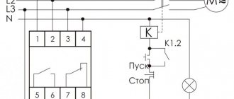
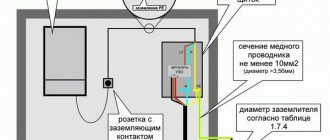
Figure No. 2. Wiring diagram in the apartment
General concept of grounding
Grounding (Pe from protection earth) is understood as the intentional connection of electrical installations or parts thereof to a conductor buried in the ground. For the system to perform its functions, it must have low resistance.
Purpose
The soil is capable of absorbing electrical charge like a capacitor with infinite capacity. This property is used to solve a number of problems.
Grounding ensures electrical contact between the electrical installation and the ground.
Areas of use
According to the method of use, grounding is divided into 2 types:
- Working. Acting as a neutral, it ensures the functioning of powerful electrical installations - transformers, generators, arresters, arc extinguishers, etc. This type also includes Pe-circuits of lightning rods and surge protection devices.
- Protective. Protects users from electric shock.
The second type comes into effect in emergency situations, when a phase is shorted to non-current-carrying metal parts of the electrical installation. Further we will talk only about this type of grounding.
What are the 4 main requirements that any grounding must meet?
1. A protective grounding device is created to effectively remove dangerous potentials to the ground circuit that accidentally penetrate conductive structures that are not intended to operate as part of an electrical circuit.
2. The charger must reliably connect all components of the electrical installation, including the structures of opening metal doors of cabinets and panels. Typically, flexible copper conductors with a yellow-green sheath are used for this.
3. The total resistance of the electrical contacts of the grounding system is regulated by clause 1.7.103. PUE. It should not be higher than 4÷30 Ohm.
This ensures the reliability of the flow of emergency currents to the solidly grounded neutral of the generator in a 220 volt network.
4. During the construction phase, it is necessary to ensure uniform distribution of loads through the installation of a potential equalization system.
Helpful information
In many situations, the issue of ensuring the safety of an electrical installation can be solved not only by installing a charger, but also by transferring the power supply network from a circuit from a solidly grounded neutral to an isolated one by simply connecting to an isolating transformer.
This method is widely used on all medical equipment, and isolation transformers are commercially available.
Principle of operation
A person touching a live body and the grounding system can be schematically represented as 2 parallel branches connected to a point with a high potential. From Ohm’s and Kirchhoff’s laws, the following relationship of currents and resistances flowing in them follows:
I1/I2=R2/R1.
In simple terms, electrical charge flows along the path of least resistance. The lower the circuit resistivity Pe, the weaker the current in the human body.
The maximum permissible resistance values for protective grounding are established by the PUE:
| Consumer | Resistance, Ohm |
| Home electrical network with a total power of simultaneously operating devices up to 100 kVA | 10 |
| The same over 100 kVA | 4 |
| Telecommunication systems | 2 |
| Server equipment | 1 |
What happens if you mix up the neutral working and grounding wires?
I wrote above that there may be voltage on the neutral working wire. This stress will end up on your body. The operating current will flow through the grounding wire, which will create a (possibly negligible) voltage on it and on the cases that are properly grounded. The likelihood of the ground wire burning out will also increase. If it burns out, the voltage will be on the housings that are properly grounded.
Here is another example of the consequences of improper grounding (Fig. 13-3). The left lamp is grounded (incorrectly) from the neutral working wire, the right one is grounded from the ground wire. Let's say our neutral main wire has burned out. Then our current will flow as follows: from the phase through the lamps to the neutral wire, then through the incorrect grounding of the first lamp to its body, then along the circuit on which the lamp hangs, along the beam, again along the circuit to the body of the second lamp and further into the grounding wire . The light will be on. But if you move the chains on which the lamps hang, they will spark, and even shock you. I have encountered this situation often.
Grounding should not be done in series.
Main types of grounding
The structure that provides contact with the ground can have different purposes. Depending on this, grounding is divided into 2 types.
Natural
Such systems use existing metal structures dug into the ground as a Pe-circuit.
Examples:
- parts of buildings and structures, reinforcement of their foundations;
- pipelines, except those transporting flammable and explosive substances;
- well casings;
- lead cable sheaths;
- rail tracks of non-electrified railways.
Natural grounding is preferable because allows you to reduce the cost of installing the system.
Artificial
In such a system, a Pe circuit is used, specially made to discharge the charge into the ground. This option is used in situations where there is no natural grounding or it has a high resistance to current flow.
Why is the neutral wire thinner than the phase wires?
The neutral wire is made thinner than the phase wires, because the current that flows through it is less than the current that flows through the phase wires.
If the load across the phases in the network is distributed (strictly) evenly, the currents in it flow from phase wires to other phase wires. The voltage drop in the network will be such that the neutral potential will be on the neutral bus and the current in the neutral wire will be zero. When the loads are uneven, a current appears in the neutral wire. The greater the unevenness, the larger it is.
Types of ground loops
There are 2 layouts of rods in multi-electrode grounding electrodes. Each has its own advantages and disadvantages.
Triangle
In this embodiment, vertical electrodes are placed at the vertices of an equilateral triangle. The minimum distance between them is 1.2 m, the optimal distance is equal to the length of the rods.
If you install the electrodes closer than 1.2 m, they will influence each other, increasing the resistance to spreading.
Advantages of a triangular scheme:
- Easy installation. Work on installing and connecting the rods is carried out in a spacious pit.
- Reliability. If one of the jumpers is destroyed, all 3 electrodes remain connected to the circuit.
- Compactness. Triangular ground electrodes, all other things being equal, occupy the smallest area.
Linear outline
In this embodiment, the electrodes are placed in a straight line. Such a contour lacks the advantages of a triangular one, but it can be increased.
Linear grounding switches are used to equip facilities where network expansion with an increase in power consumption is expected in the near future.
What is a network with a grounded neutral and a network with an isolated neutral
A network with a grounded neutral is a network in which the neutral point is connected to the ground either directly or through low resistance. This connection is usually made in a substation. A special conductor is buried in the ground. The size, material of the conductor, burial depth - this is determined by special rules set out in regulatory documents. A separate wire goes from the grounding conductor to the network. It is called PEN - conductor. Translated, this means that this wire is simultaneously
- grounding
- zero worker
What this means will be explained below.
If the neutral point is not connected to ground or is connected through a large resistance, then such a network is called a network with an isolated neutral. In such a network (here we are considering networks with voltages up to 1000 Volts) there may also be a grounding wire. Since it is only grounding, it is called PE - conductor (without N). Explanation below.
If the voltage in the network is less than 1000 Volts (for example, 380/220 Volts) and there are no transformers in the network between the substation transformer and the consumer, then this is a network most likely with a grounded neutral. An exception is networks of enterprises with special operating conditions, for example, mines.
If between the substation transformer and the consumer of electricity there is also a transformer in which the neutral point of the secondary winding is not connected to the ground, then the section from the secondary winding to the consumer is essentially a network with an isolated neutral. Examples are step-down transformers, including in taps, in machine tools, etc.
Grounding schemes
Several Pe-schemes are used in distribution networks. They are designated by an alphabetic code, the first letter of which corresponds to the method of grounding the current source, i.e. transformer or generator, the second - consumer. Next, a dash indicates the method of connecting them.
Letter meanings:
- T – earth (terra);
- N – neutral;
- C – combined;
- S – separate.
TN-C system
In this option, only the transformer at the substation (T) is grounded. On the consumer side there is a neutral (N), and the protective conductor is combined with it (C). There is nothing to connect the grounding contact to; only grounding is possible.
The only advantage of the TN-C system is its low cost, which is explained by the use of 2- and 4-core cables.
Disadvantage: low level of security.
To protect consumers, an RCD (residual current switch) is used.
The TN-C scheme is valid only in old housing stock from the times of the USSR; connecting new objects in this way is now prohibited.
Why do you need an RCD if there is grounding?
An RCD (residual current device) is a high-speed switch that works in tandem with a ground loop and responds to current leakage by breaking the circuit.
Operating principle of RCD Source tirez.ru
Circuit without grounding and RCD
When the insulation of a conductor is broken, a phase appears on the metal body of the electrical device. If the current has nowhere to go further, then when a person comes into contact with the body of an electrical device, the discharge will go through the body. The consequences will depend on many factors and the results can be different - from fear to interruptions in heart function.
Without grounding, the phase on the surface of the device with damaged wiring will remain until the input circuit breaker turns off .
RCD in a circuit without a protective conductor (TN-C)
In such a system, if the conductor insulation is broken, the RCD will not immediately operate, since no leakage current will occur. But as soon as a person touches the damaged device, part of the current will go into the body and the RCD will trip.
Even without grounding, current will flow through the human body only for the time required for the RCD to trip - usually tenths of a second. As a result, painful sensations are possible, but a fatal outcome can most likely be avoided.
Circuit with protective conductor (TN-S and TN-CS) and RCD
If an electrical appliance is in contact with the ground loop and is connected through an RCD, then if the phase conductor shorts to the metal body of the electrical appliance, leak immediately appears (which goes into the ground). The RCD trips and breaks the circuit.
Gas boiler and RCD
First of all, you need to understand that grounding a gas boiler in a private house must be carried out without fail - there are no exceptions.
Grounding the gas boiler and installing the RCD are carried out simultaneously. This is a necessary condition when connecting gas to a residential building, since surface tension forms on the body of the gas boiler during operation.
Grounding a gas boiler in a private home will avoid damage to expensive electronic equipment and prevent fire caused by static electricity. This measure, given the high explosiveness of the gas, serves as additional protection against fire.
All parts of a gas boiler must be grounded Source pinterest.com
Performing calculations
At the design stage of the ground electrode, it is necessary to select its parameters so that the resistance of the device is within acceptable limits. To do this, a series of calculations are performed.
Soil resistance
The resistance to charge spreading for a single rod is calculated by the formula:
Ro = (Peq/2π*L) *{ln(2L/d) + 0.5 ln((4T + L)/(4T – L)}
If the electrode is placed in heterogeneous soil (2-layer), the resistance is calculated using the formula:
Peq = (Ψ*P1*P2*L)/( P1(L – H + tg) + P2(H – tg)), where
- Ψ – coefficient taking into account seasonality;
- P1 and P2 – specific resistivity of the first and second layers of soil, Ohm/m;
- H – thickness of the top layer, m;
- T – depth of immersion of rods;
- Tg – depth of the vertical pin (distance from the top of the ground electrode to the surface of the earth).
Dimensions and distances for ground electrodes
The minimum length of the rod is 2.5 m. If this condition is met, the base of the electrode with a 100% guarantee will be below the freezing mark of the soil, where acceptable resistance to charge spreading is maintained all year round.
The method for calculating the number of rods depends on what the ground electrode consists of.
If only from vertical electrodes, use the formula:
No = Ro *Ψ/Rн, where
Rн – resistance to spreading recommended by standards.
If the structure has horizontal elements, the number of rods is equal to:
N = Ro/( Rв*ηв), where
ηв – grounding conductor utilization coefficient, taking into account the mutual influence of the electrodes on each other.
In a linear design it is higher, so the calculation result is rounded up.
Structure of the Earth
Based on various studies, scientists have divided the Earth into three parts - core, mantle and crust.
The core is the heaviest part of our planet, its radius is about 3500 km, and its temperature is 4000 degrees and above. It is supposedly divided into an outer liquid part, consisting of sulfur and iron, and a solid inner part, containing an alloy of iron and nickel.
The mantle is not yet available for full research, so all data was obtained using geophysical and geochemical methods. It is in a solid state, from 30 to 3000 km from the surface and consists of ultrabasic rocks, refractory elements.
On top of the mantle lies the earth's crust, consisting mostly of rocks and minerals. It is on it that the oceanic and continental crust is located. Its thickness ranges from 5 to 10 km under water and up to 80 km on land.
Scientists have hypothesized that the oceanic crust was initially formed, and as a result of various processes that occurred inside the planet, folds were formed - sections of mountains. Over time, the thickness of the crust increased, forming the continental crust.
Norms and requirements
According to the PUE, the following can be used as electrodes:
- strip with a cross section of 48 sq. mm;
- rod - from 10 sq. mm;
- corner with a thickness of 4 mm;
- a pipe with a diameter of 2.5 cm and a wall thickness of 3.5 mm.
These dimensions are adopted in order to ensure the durability of the rods within 5-10 years.
Pin driving depth
According to the PUE (Chapter 1.7.), the minimum immersion depth of the rod is 0.7 m. The strip connecting the vertical grounding conductors is placed on the edge.
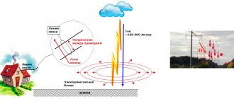
Grounding and lightning protection
The PUE prescribes connecting the protective grounding circuits of electrical installations and lightning protection of the second and third categories, i.e. all objects except explosive ones. Communication is carried out by at least 2 conductors (PUE, clause 1.7.55).
If the circuits remain disconnected, a breakdown between the lightning rod and the home electrical network may occur during a lightning strike. This will lead to failure of the electronics, fire or destruction of some elements, incl. plastic water pipes.
general description
Among the terrestrial planets in the solar system, which includes Mercury, Venus and Mars, Earth is the largest. The planet is the third in distance from the Sun, it is the fifth in diameter, mass and density. The age of our planet is compared to the age of the entire solar system and is approximately 4.5 billion years. There is a hypothesis that the Earth was formed from gas and dust that remained from the formation of the sun. The oldest rocks that have been studied were formed approximately 100 - 200 million years ago. And conditions favorable for the emergence of life on the planet arose only 3.5 billion years ago. We, as a modern type of person, were formed only 40,000 years ago.
The earth is spherical in shape, flattened at the poles. The length of the Earth's equator is 40,076 km, the equatorial radius is 6,378 km, the polar radius is 6,357 km and the average radius is 6,371 km.
The Earth, and we along with it, revolves around the Sun in a circular orbit, the radius of which is 150 million km. The period during which the Earth rotates in an elliptical orbit occurs at a speed of 29.8 km/s and lasts 365 days. The approximate distance to the Sun is 149,543,000 kilometers.
The earth also rotates around its imaginary axis (from west to east). A full revolution is completed in approximately 23 hours 56 minutes. The rotation axis is tilted 66.5 degrees relative to the orbital plane, and as a result of this movement, the cycle of day and night occurs. And since the earth simultaneously rotates around the Sun, sometimes approaching and sometimes moving away from it, the seasons change.
Compliance with safety regulations
Before carrying out any work on the grounding device, you must do one of two things:
- cut off power to the house;
- disconnect the ground wire from the main bus.
Grounded parts of electrical installations may become live at any time, incl. and during manipulations with the contour. If it is not turned off, the user will receive an electric shock.
Before performing work on the electrical panel, the house must also be de-energized. After turning off the machine, make sure there is no voltage using the phase indicator (indicator screwdriver).
How to simply imagine the work of grounding in household wiring
The danger of electrical energy very well helps to understand the principle of operation of a mousetrap: a hungry mouse comes out of a hole, and in front of it on a special stand lies a delicious crust of bread, flavored with a drop of aromatic oil.
The animal approaches the offered treat, touches it slightly, and the hidden force of a powerful spring instantly hits the mouse with a metal frame... Just like that, completely unexpectedly, a person gets injured from electricity.
Electric current always flows only within a closed circuit under the influence of applied voltage. It is directed from a potential of a larger value to a smaller one. When this chain is broken, there is no current, and the risk of falling under its influence is enormous.
In our homes there are quite a few factors when dangerous potential, for example, phases, can penetrate current-carrying structures (the body of a household appliance) and remain on them because the further circuit is insulated by a dielectric layer.
This property is used by “jokers” who do not fully understand the consequences of their actions.
One has only to create contact of high potential with the ground, and a current immediately flows through it (the soil is highly conductive), removing this energy. If a living creature gets in his way, then his fate is not enviable.
Therefore, all conductive housings of modern household appliances are specially (intentionally) connected through grounding devices (GD). This achieves instant drainage of a dangerous charge through a dedicated earth circuit in a network with a solidly grounded neutral.
The PE conductor chain creates reliable electrical contact through the ground with the voltage source of the main distribution board (MSB) at the supply substation.
When the potentials of the phase located on the housing and the ground are connected, a short circuit current occurs. It must be switched off by an SQ circuit breaker selected according to local conditions.
This process is called protective shutdown. It is described in detail in Chapter 1.7 of the PUE.
A grounding scheme with a solidly grounded neutral is used in our country at 0.4 kV substations with three-phase generators. Their windings are assembled in a star configuration with a common point connected to a grounding device.
Consumers are connected in the same way. This connection ensures that the potentials of the ground and the neutral wire are equal.
Grounding is created in advance. Its purpose is to protect people and electrical devices from exposure to dangerous electric current.
In addition to the protective function, it can also perform technological tasks related to the normal operation of electrical equipment.
Why is a neutral wire needed?
I wrote above that the neutral and grounding conductors usually come from the substation in one wire, and why a grounding wire is needed. Now about the function of the neutral working wire. It is needed to avoid the “phase imbalance” that I described above. Although electricians strive to achieve load uniformity (for example, by connecting an equal number of apartments to each phase), unevenness still occurs. You flipped the switch and you have already changed the load ratio. Why is there no “phase imbalance” when there is a neutral wire? Firstly, when many consumers are connected to the neutral wire, load unevenness appears to a much lesser extent. When you turn on the TV to watch football, there is a chance that your neighbors, who are “sitting” on other phases, also turn on their TVs. Secondly, the neutral wire is connected to the neutral. Neutral is a point in the secondary winding of a transformer to which three identical symmetrical windings are connected at one end. At the other end they are connected to the phase wires. Let's assume that the load is distributed evenly across the phases. And suddenly in some phase it increases.
The following will happen:
- The load resistance in this phase will decrease.
- The voltage drop across the load will decrease, and therefore
- The voltage between this phase and zero should decrease, but
- The current in the load will increase, and therefore
- The current in the corresponding third of the secondary winding will increase
- The magnetic field of the secondary winding will increase
- This magnetic field is directed in such a way that it reduces the inductive reactance of the corresponding sector of the primary winding, and therefore
- This inductive reactance will decrease further
- In the primary winding (in its corresponding third) the current will increase, and therefore
- Its magnetic field will strengthen
- This magnetic field will create a higher voltage in the corresponding sector of the secondary winding, and therefore
- The voltage between this phase wire (phase) and neutral (zero) will remain stable
This ensures uniformity of phase voltages.
Tips and tricks
- Electricians recommend grounding all household appliances and sockets in the apartment;
- Electrical appliances cannot be grounded in a chain through each other. This may cause electromagnetic incompatibility and ground loop failure;
- special terminals should be used; twisting at the joints is not allowed;
- Only one wire can be connected to each PE bus terminal.
Grounding will make it safe to use electrical appliances in the apartment. There are several connection systems, the most common is TN-C; it does not have a separate grounding conductor and is outdated. To protect a person from electric shock, you can install an RCD and assemble your own protective circuit. If you follow safety precautions and PUE standards, this will not cause much difficulty.
Why does the neutral wire burn out?
Because current flows through it. It usually burns out in places where connections were made poorly. If the resistance of the connection is high, heat begins to be generated on it. Heat causes the connection to oxidize, its resistance increases even more, and it heats up even more. If the process starts, sooner or later the wire will burn out. Remember this simple wisdom: the larger the contact area, the more reliable the connection. And if a twist 1 cm long burns out in a month, 2 cm in a year, then a twist 5 cm long and longer will last (maybe) forever. Make the twist longer, do you really feel sorry for the wires?
For reliability, you can also twist a piece of uninsulated wire onto the twist.
It’s even better to solder or weld the twist. Nowadays, special caps are used that are screwed onto connections - “PPE”.
By themselves, they only increase the reliability of the connection, but I don’t believe that it’s enough to screw on the PPE and reliability is ensured. Carefully clean the surfaces to be joined (with a file, knife), but not with sandpaper (its grains can worsen the quality of the connection). When making a loop of wire for a bolted (screw) connection, weld it several times with a file (file) so that the contact area is larger. Tighten the screw or bolt until it stops, current will flow through it. Take care that the connection does not weaken over time. Use a good, non-rusty, non-oxidized washer or Grover washer. Do not connect copper and aluminum wires directly, use (steel) clamps for this. Top
Report bugs by email
To home page