When developing electronic circuits, there is often a need for a low-power voltage stabilizer or a reference voltage source. A number of fixed voltages are closed by unregulated integral stabilizers. Adjustable ones are built on the LM317 chip, but it has certain inherent disadvantages and often unnecessary functionality. In many cases, the problem will be solved by the TL431 chip, which allows you to obtain a low-power source of stable voltage that can be adjusted from 2.5 to 36 V.
Description
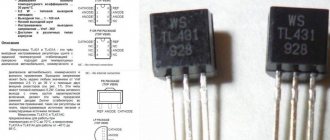
TL431 – datasheet in Russian.
The TL431 is a parallel-type adjustable voltage regulator (integral analogue of a zener diode) and is designed for use as a reference and adjustable zener diode with guaranteed thermal stability over the applicable commercial temperature range. The output voltage can be set at any level from 2.495 V (VREF) to 36 V, for this two external resistors are used, which act as a voltage divider.
This regulator has a wide operating current range from 1.0 mA to 100 mA with a dynamic resistance of 0.22 ohms. The TL431's active output elements provide sharp turn-on characteristics, making it perform better than conventional zener diodes in many applications.
±0.4% voltage reference accuracy (TL431B) eliminates the need for a variable resistor, saving costs and reducing drift and reliability issues.
Key Features of TL431
Basic characteristics, knowledge of which is sufficient to perform 90+ percent of the tasks that arise when developing electronic circuits:
- output voltage limits - 2.5...36 V (this can be considered a disadvantage, since modern regulators have a lower limit of 1.5 V);
- the highest current is 100 mA (it is small, comparable to a medium-power zener diode, so you should not overload the microcircuit, it has no protection);
- internal resistance (impedance of an equivalent two-terminal network) – about 0.22 Ohm;
- dynamic resistance – 0.2…0.5 Ohm;
- rated value Uref=2.495 V, accuracy – depending on the series, from ±0.5% to ±2%;
- operating temperature range for TL431С is 0…+70 °С, for TL431A – minus 40…+85 °С.
Other characteristics, including graphs of parameters depending on temperature, can be viewed in the datasheet. But in most cases they won't be needed.
TL431 connection diagrams
The voltage at the output of this circuit will be equal to the voltage of the internal ION TL431, that is, 2.5 V.
The circuit below replaces conventional zener diodes with stabilization voltages from 2.5 to 36 volts. By changing the values of the resistors in the voltage divider (R1, R2), you can change the output voltage.
The recommended maximum current for the TL431 is 100 mA. If you need a more powerful zener diode, you can use the following circuit. The maximum current will depend on the transistor used.
The figure below shows a circuit of a series-type compensation voltage stabilizer. Compared to the previous circuit, such a stabilizer has a lower input resistance, a higher stabilization coefficient, and a higher output current.
One of the typical switching circuits for the TL431 is a current stabilizer.
Using the TL431, you can increase the output voltage of the 7805 regulator and the like.
The following figure shows the voltage indicator circuit. The LED will light up when the monitored voltage is between the upper level (set by R3,R4) and the lower level (R1,R2).
Comparator with temperature-compensated threshold.
How TL431 works
If the control voltage exceeds 2.5 volts (internal reference), the output transistor TL431 turns on, causing current to flow between the cathode and anode of the TL431. If the control voltage is less than 2.5 volts, then the current does not flow between the cathode and the anode (or rather, it is very small).
TL431 is one of the most widely produced integrated circuits; since its release in 1978, TL431 has been installed in most power supplies for computers, laptops, TVs, video-audio equipment and other consumer electronics. The TL431 is a precision programmable voltage reference. This popularity is due to low cost, high accuracy and versatility.
The principle of operation of the TL431 is easy to understand from the block diagram: if the voltage at the input of the source is lower than the reference voltage Vref, then the output of the operational amplifier is low voltage, respectively, the transistor is closed and the current does not flow from the cathode to the anode (more precisely, it does not exceed 1 mA). If the input voltage exceeds Vref, the operational amplifier will open the transistor and current will begin to flow from the cathode to the anode.
The simplest type of stabilizer is parametric, which can be easily built on the TL431: to set the stabilization voltage, you will need two resistors R1 and R2, the voltage for which the TL431 will be 'programmed' can be determined by the formula: Uout = Vref ( 1 + R1/R2 ). It turns out that the greater the ratio of R1 to R2, the greater the output voltage. The microcircuit actually stabilizes the voltage at its input at a level of 2.5 V. Given the value of resistance R2 and the required output voltage, R1 can be calculated using the formula: R1=R2(Uout/Vref – 1). In this circuit, R3 is calculated in exactly the same way as if a regular zener diode were used, i.e. depends on the output voltage, input voltage range and load current range. But there is also a significant difference: in this circuit, you should not install a capacitor at the output, since this capacitor can cause the generation of parasitic oscillations. In a circuit with a conventional zener diode, such problems do not arise.
Read also: How much does a 6x40 dowel nail weigh?
Examples of connection schemes
One of the options for the TL431 switching circuit is a regular comparator. You can build some threshold relays on it - for example, a level relay, a lighting relay, etc. Only its reference voltage source is built-in and cannot be adjusted, so the current and voltage drop are regulated through the sensor.
As soon as 2.5 V drops on the sensor, the output transistor of the microcircuit opens, current flows through the LED and it lights up. Instead of LED, you can use a low-power relay or a transistor switch that switches the load. Resistor R1 can be used to adjust the response level of the comparator. R2 serves as a ballast and limits the current through the LED.
But such inclusion does not make it possible to use all the capabilities of the TL431 - the comparator can be built on any other microcircuit that is more suitable for such relays. The same assembly is designed for other purposes.
The simplest circuit for connecting the TL431 in parallel stabilizer mode is a 2.5 V reference voltage source. For this, you only need a ballast resistor that will limit the current through the output transistor.
Important! Unlike the classic zener diode switching circuit, you should not install a capacitor parallel to the output. This can lead to parasitic oscillations. In general, it is not needed, since the developers have taken measures to reduce output noise. But because of this, the microcircuit cannot be used as a basis for a noise generator, like a regular zener diode.
The capabilities of the microcircuit are more fully used in a feedback circuit formed by resistors R1 and R2.
Main technical characteristics of TL431:
- anode-cathode voltage: 2.5…36 volts;
- anode-cathode current: 1...100 mA (if you need stable operation, then you should not allow a current less than 5 mA);
The accuracy of the TL431 voltage reference depends on the 6th letter in the designation:
It can be seen that the TL431 can operate in a wide range of voltages, but the current capacity is not so high, only 100 mA, and the power dissipated by such cases does not exceed hundreds of miles of watts. To obtain more serious currents, the integrated zener diode should be used as a reference voltage source, entrusting the regulating function to powerful transistors.
Analogs TL431
IC tl431 analogue, which needs to be selected, belongs to the control zener diodes. Therefore, it is necessary to select a similar IC based on electrical parameters: reference voltage, input voltage, operating current and design features.
Carefully. Analogues can be: complete, closest and functional. Depending on the new part, additions and changes to the electronic circuit where it will be installed (replaced) are possible. When selecting an analogue, you should take into account that the first two letters before the numbers are the name of the manufacturer.
For example, the transistor az431, the characteristics of which, when tested, coincide with tl431, is the same, it’s just a different manufacturer.
Some analogues for TL431
compensation voltage stabilizer
The principle of the compensation stabilizer on the TL431 is the same as on a conventional zener diode: the voltage difference between the input and output is compensated by a powerful bipolar transistor. But the accuracy of stabilization is higher due to the fact that feedback is taken from the output of the stabilizer. Resistor R1 must be calculated for a minimum current of 5 mA, R2 and R3 are calculated in the same way as for a parametric stabilizer.
To stabilize currents at the level of units and tens of Amperes, one transistor in a compensation stabilizer is not enough; an intermediate amplifier stage is needed. Both transistors operate according to an emitter follower circuit, i.e. The current increases, but the voltage does not increase. The figure shows a real circuit of the compensating stabilizer on the TL431; new components have appeared in it: resistor R2 limits the base current of VT1 (for example, 330 Ohms), resistor R3 compensates the reverse collector current of VT2 (which is especially important when heating VT2) (for example, 4.7 kOhm ) and capacitor C1 - increasing the stability of the stabilizer at high frequencies (for example, 0.01 µF).
Time relay
The TL431 has found its use not only as a voltage reference source, but also in many other applications. For example, due to the fact that the input current of TL431 is 2-4 μA, a time relay can be built on the basis of this microcircuit: when contact S1 opens, C1 begins to slowly charge through R1, and when the voltage at the input of TL431 reaches 2.5 V, the output transistor DA1 opens and through The LED of the PC817 optocoupler will begin to flow current, and accordingly the phototransistor will open and close the external circuit. In this circuit, resistor R2 limits the current through the optocoupler and stabilizer (for example, 680 Ohms), R3 is needed to prevent the LED from igniting from the TL431’s own current (for example, 2 kOhms).
A simple lithium battery charger.
The main difference between a charger and a power supply is a clear limitation of the charging current. The following circuit has two limiting modes:
As long as the output voltage is less than 4.2 V, the output current is limited; when the voltage reaches 4.2 V, the voltage begins to be limited and the charging current decreases. In the following diagram, current limitation is carried out by transistors VT1, VT2 and resistors R1-R3. Resistor R1 performs the function of a shunt, when the voltage across it exceeds 0.6 V (opening threshold VT1), transistor VT1 opens and closes transistor VT2. Because of this, the voltage at the base of VT3 drops; it begins to close and, consequently, the output voltage decreases, and this leads to a decrease in the output current. This is how current feedback and stabilization works. When the voltage approaches the level of 4.2 V, DA1 begins to come into operation and limit the voltage at the output of the charger.
Read also: Induction and inductance, what is the difference
And now a list of circuit component values:
- DA1 – TL431C;
- R1 – 2.2 Ohm;
- R2 – 470 Ohm;
- R3 – 100 kOhm;
- R4 – 15 kOhm;
- R5 – 22 kOhm;
- R6 – 680 Ohm (needed to adjust the output voltage);
- VT1, VT2 – BC857B;
- VT3 – BCP68-25;
- VT4 – BSS138.
21 thoughts on “TL431 switching circuit, TL431 pinout”
K1242ER1AP manufactured by Integral Minsk
I would not call the low accuracy of the TL431 its disadvantage; it is not a stabilizer as such, but a reference voltage source for it. Using various peripherals, you can solve various problems in terms of power, accuracy, reliability, etc. Now, external circuits can be anything, but they are controlled by the same device - TL431. This is what makes it so widespread and in demand. I liked the charging circuit, where regulation of both current and voltage is necessary; both bipolar and unipolar transistors are used - each in its own mode.
Yes, a capacitor should not be placed between the anode and cathode of this “zener diode” under any circumstances. I encountered self-excitation of the voltage stabilizer circuit when, out of inexperience, I decided that with a capacitor at the output of the reference voltage source on the TL431, the circuit would work more stable. I installed a 10 nF capacitor, and the circuit started up, producing a “porridge” of pulses at the output instead of a constant voltage. Not surprisingly, for the operational amplifier included in the TL431, such a parameter as the maximum load capacitance must be taken into account as for any other op-amp.
I already wrote above that it is strange to use a precision reference voltage source in the form of a stabilizer. It's even stranger how much stability can be achieved with a capacity of tens of nanometers. Stability of the set voltage by shunting and creating a parasitic OS? Or a day off? Of course he'll get excited.
What was there about the reference source in the form of a stabilizer? The reference in the stabilizer was used for its intended purpose, as a reference with which the output was compared