Features of operation, ease of inclusion in many circuits and good characteristics have made the TL431 chip a very popular adjustable stabilizer on the market. With a minimal set of additional electronic components (several resistors and capacitors), it is capable of providing operating voltage in the range from 2.5 to 36 V with a stabilization current from 1 to 100 mA. To obtain large values, powerful transistors are usually added to the TL431 output.
This device is also called a controlled programmable zener diode. It was first introduced to the world by the American company Texas Instruments (TI) back in 1977. Since then, it has been constantly improved and is now an integral part of many modern switching power supplies, where it serves as a reference voltage source. It can be an excellent replacement for Zener diodes in various electronic circuits.
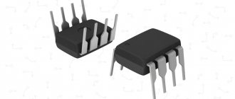
Tsokolevka
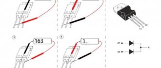
The pinout of the TL431 depends on the housing design of the device in which it is located. There are five varieties in total: for installation in holes: TO-92; for surface mounting: SOT-23, SOT-25, SOT-89 and SOP-8. The electronic circuits located inside such plastic packages have only 3 contacts with a purpose: 1 – control electrode; 2 – anode; 3- cathode. Some types of housings of this microcircuit have more metal pins, but they are not used or are combined with neighboring ones. How this is done is clearly shown in the figure.
Mobile phone charger
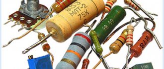
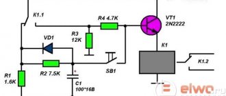
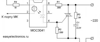
The stabilizer can be used as a kind of current limiter. This property will be useful in devices for charging mobile phones.
If the voltage in the output stage does not reach 4.2 V, the current in the power circuits is limited. After reaching the declared 4.2 V, the stabilizer reduces the voltage value - therefore, the current value also drops. Circuit elements VT1 VT2 and R1-R3 are responsible for limiting the current value in the circuit. Resistance R1 bypasses VT1. After exceeding 0.6 V, the VT1 element opens and gradually limits the voltage supply to the bipolar transistor VT2.
Based on transistor VT3, the current value decreases sharply. Transitions are gradually closing. The voltage drops, which causes the current to drop. As soon as U approaches 4.2 V, the tl431 stabilizer begins to reduce its value in the output stages of the device, and the charge stops. To manufacture the device, you must use the following set of elements:
- DA1 – TL431K - if this element is not available, then it can be replaced with tl4311, tl783ckc;
- R1 – 2.2 Ohm;
- R2 – 470 Ohm;
- R3 – 100 kOhm;
- R4 – 15 kOhm;
- R5 – 22 kOhm;
- R6 – 680 Ohm;
- VT1, VT2 – BC857B;
- VT3 – az431 or az339p;
- VT4 – BSS138.
It is necessary to pay special attention to the transistor az431 . To uniformly reduce the voltage in the output stages, it is advisable to install the az431 transistor; the datasheet of the bipolar transistor can be seen in the table.
It is this transistor that smoothly reduces the voltage and current. The current-voltage characteristics of this element are well suited for solving the task.
The TL431 operational amplifier is a multifunctional element and makes it possible to design various devices: mobile phone chargers, alarm systems and much more. As practice shows, the operational amplifier has good characteristics and is not inferior to foreign analogues.
TL431 Specifications
Let's consider the maximum permissible performance characteristics of the microcircuit. If during its operation they are exceeded, the device will inevitably fail. Long-term operation with parameters close to the limit values is also not allowed. Let's look at them in more detail:
- cathode output voltage (VKA), relative to the anode terminal, up to 37 V;
- possible current values: for continuous cathode output (IKA) from –100 mA to 150 mA; for reverse input from -50 mA to 10 mA;
- typical impedance up to 0.22 Ohm;
- power dissipation (for different types of packaging) PD: 0.8 W (SOT-89); 0.78 W (TO-92); 0.75 W (SO-8); 0.33 W (SOT-23); 0.5 W (SOT-25);
- crystal temperature (TJ): operating: 0…+70 °C; -40 ... +125OS (for some car versions); maximum (TJmax) up to +150°C;
- body thermal resistance RθJC: 97OC/W (D); 156 OS/W (LP); 28 OS/W (KTP); 127OS/W (P); 52OS/W (PK); 149OS/W (PW);
- storage temperature: -65… +150 °C.
The maximum power dissipation can be calculated using the standard formula PD= (TJmax-TA)/ RθJC. In it, TA is the ambient temperature.
Recommended operating parameters
In operating conditions, the recommended values for using the TL413 are: input reference voltage (VREF) no more than 36 V; cathode current (IKA) should be in the range from 1 to 100 mA; compliance with temperature conditions of use. It is worth considering that with IKA <5 mA, this microcircuit may function unstable. Below are the electrical parameters of the device, measured at a temperature of TA = 25°C.
Safe Operation of the TL431
During operation, it is necessary to comply with the environmental parameters described by the manufacturer. This is necessary not only for longer component life, but also for predictable behavior. The table below shows the performance of the TL431 at 25°C.
The element must not be overloaded; its maximum input voltage is 36V.
It is best that the load current is at least 5mA, otherwise the microcircuit may operate unstable and unpredictably.
TL431 connection diagrams
Let's figure out how the TL431 works using the example of a simple stabilization circuit, consisting of a zener diode itself and one resistor. The positive pole of the power supply is connected to the cathode, and the negative pole of the power supply is connected to the anode. To turn on the microcircuit, a reference voltage (Vref) is applied to its control electrode.
If its value is more than 2.5 V, then the zener diode will almost immediately open and begin to pass current through itself (IKA), which can be used to power the corresponding load. Its value will increase as the Vin level increases. IKA can be determined by the formula IKA = (Vin—Vref)/R. In this case, the output voltage of the circuit will be stabilized at the reference level (VKA = Vref), not exceeding 2.5 V and regardless of the Vin supplied at the input.
The maximum IKA value of the TL431 is limited not only by 100 mA, but also by the power dissipation into its housing.
Calculation of a parametric stabilization scheme
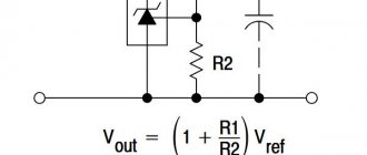
To obtain a higher voltage at the output of the microcircuit (up to 36 V), a resistive divider is additionally connected to its control electrode. It consists of two resistors (R1 and R2) connected between the cathode and anode. In this case, the internal resistance of the zener diode increases by (1 + R1/R2) times.
To calculate the stabilization circuit on the TL431, initial data on the input (VIN) and output (VKA) voltages, as well as currents: stabilization (IKA) and load (IL) are required. With this data, you can calculate the values of other electronic components shown in the figure below.
The output voltage and resistance ratings are related to each other by the following formula VKA= Vref *(1 + R1/R2)+ Iref *R1. Where Vref = 2495 mV and Iref = 2 µA are typical values, they are indicated in the electrical parameters from the datasheet for the device.
Resistance R1 can also be taken from the datasheet. Most often they are taken with ratings from 10 to 30 kOhm. The value of R1 is limited by the small reference current (Iref = 2 µA), which is often neglected for calculations of stabilization circuits on the TL431. Therefore, to calculate the value of R2, without taking into account Iref, you can use the following formula R2=R1/((VKA/Vref)-1).
Stabilization voltage adjustment
To build circuits with the ability to manually adjust the output voltage, a potentiometer is installed instead of the usual R1. The value of the limiting resistor R, which resists the current at the input (IIN), is calculated using the formula R = (VIN-VKA) / IIN. Here IIN = IKA+ IL.
Despite the advantages of the TL431 microcircuit, it also has a very significant drawback - it is a small load current that it can withstand. To solve this problem, powerful bipolar or field-effect transistors are included in the circuit.
Examples of various circuits based on the TL431 zener diode can be seen in the following video.
Notes and links
1. Due to the fact that TL431 does not have the most common function, there is no standard name for this kind of item. Various datasheets give the following names: “adjustable shunt regulator”, “programmable precision voltage reference”, “programmable shunt voltage reference”, “programmable zener diode”. 2. I dug up the origins of the TL431 in the Voltage Regulator Handbook, published by Texas Instruments in 1977. The predecessor to this IC was the TL430, released as an adjustable shunt regulator in 1976. The TL431 was created in 1976 as an update to the TL430 with improved accuracy and stability, and was therefore named an adjustable precision shunt regulator. In 1977 it was announced as one of TI's future products, and released for sale in 1978. Another announcement was the TL432, which would have been called a “Timer/Stabilizer/Comparator Layout Block” and consisted of a voltage reference, comparator and transistor amplifier , according to the preliminary datasheet. But by the time the TL432 was released, the plan to provide "building blocks" had been abandoned. TL432 has become an analogue of TL431 with different pin layouts for more convenient board layout (datasheet). 3. Modern ATX power supplies (example one, example two) often contain three TL431. One is for feedback in the backup power supply, the second is for feedback in the main power circuit, and the third is taken as a linear regulator for the 3.3V output voltage. 4. It is interesting to look at switching power supplies that do not use TL431. Earlier models used a reference zener diode as the voltage reference. For example, this was practiced in the first copies of power supplies for the Apple II (Astec AA11040), but they soon replaced the zener diode with a TL431 - Astec AA11040, revision B. The Commodore CBM-II, model B, used an unusual solution - TL430 instead of TL431. The original power supply for the IBM PC used a zener reference diode (along with a bunch of op amps). Later PC power supplies often used the TL494 PWM controller, which already contained a reference voltage source for the secondary circuit. Other power supplies could contain SG6105, which already includes two TL431. Phone chargers typically use the TL431. It is rare to find a cheap counterfeit of this element: it is easier to take a reference zener diode instead and save a couple of cents. Another exception may be chargers such as those for the iPad. They implement stabilization in the primary circuit and do not require any feedback from the output voltage. In my article about power supplies I described this in more detail. 5. The TL431 is available in more housing options than I thought. In two photographs, the TL431 is made in a “transistor” package with three legs (TO-92). The remaining photos show the SMD version in SOT23-3. The TL431 is also available in 4-pin, 5-pin, 6-pin, and 8-pin SMD packages (SOT-89, SOT23-5, SOT323-6, SO-8, or MSOP-8). It can also be found in a larger TO-252 variant or even as an 8-pin IC (DIP-8). (Pictures). 6. More detailed information about how a bipolar transistor is designed in silicon can be found in many places. Semiconductor Technology gives a good overview of the NPN transistor design. The Basic Integrated Circuit Processing presentation describes chip manufacturing in great detail. Even the diagrams with are very interesting. 7. You may be wondering why there is a terminological division into collector and emitter, if in our simple transistor circuit they are absolutely symmetrical? After all, both are connected to the N-layer, why should there be any difference? But as you can see in the photo of the crystal, the collector and emitter are not only very different in size, but also doped differently. If you swap the collector and emitter positions, the transistor will have a very weak transmission coefficient. 8. pnp transistors in TL431 have a circular structure, which makes them very different from npn. This circular structure is illustrated in the book Designing Analog Chips by Hans Camenzind, author of the 555 timer. If you want to learn more about how analog chips work, I recommend this book, which explains the subject in detail with a minimum of mathematics. Free PDF or paper version. In addition, you can read about the structure of pnp transistors in “Principles of Semiconductor”. And the book “Analysis and Design of Analog Integrated Circuits” talks about detailed models of bipolar transistors and how they are implemented in microcircuits. 9. The transistors and resistors on the chip I examined have completely different characteristics compared to those previously published. These characteristics fundamentally determine the operation of a zener diode with a bandgap voltage. Specifically, in the previous circuits, R2 and R3 were in a ratio of 1 to 3, and Q5 had an emitter area twice as large as Q4. Looking at the photo of the crystal, I see that R2 and R3 have the same resistance, and Q5 has an emitter area 8 times larger compared to Q4. Based on such relationships between characteristics, we obtain another ΔVbe. In order to compensate for the difference between the actual characteristics and the calculated ones, in previous circuits R1 and R4 were also made different from those on the chip. I will explain this point in more detail later in the article, but just note: Vref = 2*Vbe + (2*R1+R2)/R4 * ΔVbe should be about 2.5 volts. Please note that it is not the specific resistance of the resistors that is important, but rather their ratios. As I wrote earlier, this helps counteract poor resistor tolerances on the chip. On-chip Q8 is formed from two parallel transistors. But I can't understand what's behind this strange decision. I expected Q8 and Q9 to be identical in order to build a balanced comparator. My main theory is that this is done to adjust the reference voltage so that it reaches 2.5V. B. Engl suggested that this could help the device work better at low voltage. 10. I will not go into details of the implementation of a zener diode with a bandgap voltage here, except to mention that while its name may sound like the name of some crazy quantum device, it is, in fact, just a pair of transistors. To understand how this zener diode works, you can look at the article “How to make a bandgap voltage reference in one easy lesson” by Paul Brokaw, the inventor of the zener voltage reference diode of the same name. In addition, there is also such a presentation. 11. In a sense, the bandgap circuit in the TL431 works in the opposite direction to a conventional bandgap, which supplies the correct voltages to the emitter to produce the required output. TL431 takes the reference voltage as an input, and uses the emitters as input signals for the comparator. In other words, contrary to the block diagram, inside the TL431 the input "ref" signal is not compared to any stable reference voltage. Instead, the "ref" input generates two signals for the comparator, which are the same if the input voltage is 2.5 volts. 12. There are many articles about the TL431, but they are all technical and expect the reader to have some basic knowledge of automatic control theory, Bode plots, and so on. “The TL431 in Switch-Mode Power Supplies loops” is a classic article from Christophe Basso and Petr Kadanka. It explains the operation of the TL431 in the feedback compensation circuit in existing power supplies. The book contains detailed drawings and descriptions of the internal structure of the element. There are also interesting articles on powerelectronics.com. The article "Designing with the TL431" by Ray Ridley, for Switching Power Magazine, provides a detailed explanation of how to use the TL431 in power supply feedback circuits and also explains how the compensator works. You can pay attention to the presentation “The TL431 in the Control of Switching Power Supplies” from ON Semiconductor. Of course, the datasheet also contains drawings of the internal structure of the chip. Strangely, the resistances in these drawings are different from those I got from examining the photo of the crystal.
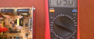
How to check with a multimeter
TL431 cannot be tested with a multimeter as it is not a simple zener diode but an integrated circuit. The resistances between its terminals differ from different manufacturers. Therefore, in order to verify its serviceability, they usually assemble the simplest verification schemes.
To check in the circuit shown in the figure on the left, 12 V is supplied to the input. If the device is working properly, then a voltage of 4.9-5.0 V should appear at the output, and when the S1 button is closed - 2.5 V. A multimeter, in this case, is needed to measure the test results .
The TL431 can also be tested in another LED test circuit (picture on the right). When the resistance R2 of the potentiometer changes, 2.5 V appears on the control electrode. The diode should jump into a glowing state. This will mean that the device is working properly. This operating principle can be used to create a battery discharge indicator.
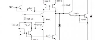
Electronic element device
The microcircuit has a simple design consisting of the following elements: a housing, an operational amplifier (op-amp), an output transistor tl431, and a reference voltage source. The peculiarity of this microcircuit is that it performs the functions of a zener diode.
A 2.5-volt reference voltage source, which has high stability, is connected to the inverse input of the op-amp (-), the emitter of the transistor and ground using two common points; a silicon diode is also included in the reference pressure circuit. It is designed to prevent the creation of reverse current and protects against polarity reversal. Direct input ® is designed to receive signals from other boards, as well as power the amplifier. It is connected via a diode to the collector of the transistor also through a common point. The output of the op-amp is connected to the base of the transistor.
It should be remembered that the transistor used in the microcircuits of this series can withstand loads up to 0.1 A and 36 V.
Manufacturers
Due to its good parameters, reliability and low cost, TL431 is used in various technical solutions. Therefore, many foreign companies are engaged in its production. There is even a fully translated datasheet tl431 in Russian from Texas Instruments (TI). Here are links to some datasheets of devices sold in the Russian Federation: ON Semiconductor, STMicroelectronics, Nexperia, HTC Korea, NXP Semiconductors. There are still manufacturers of these products, but they are difficult to find in Russian stores. These include: Unisonic Technologies, Motorola, Fairchild Semiconductor, Diodes Incorporated, HIKE Electronics, Calogic, Sangdest Microelectronic (Nanjing), SeCoS Halbleitertechnologie GmbH, Hotchip Technology, Foshan Blue Rocket Electronics, etc.