A capacitor is an electronic element classified as passive. Its main ability is to slowly (from an electrical point of view, within a few seconds) accumulate a charge, and, if necessary, instantly release it. During recoil, this discharge occurs. Unlike a battery, a capacitor releases all its energy in a pulse rather than gradually, after which the charging cycle begins again.
The main characteristic of this element is capacity. It is measured in pF and μF - pico- and microfarads. In addition, each capacitor has certain characteristics of operating voltage and breakdown voltage at which it fails. They are either indicated on the body by numbers, or they have to be determined from catalogs, guided by the standard size and color marking of the part.
Due to their design features, capacitors belong to the category of elements that most often fail on an electronic board. Therefore, any repair of a device containing electronics (from a microwave oven to a PC motherboard) begins with checking these elements for functionality - visually, using a multimeter or other devices.
What is a capacitor
A capacitor is an electrical element that is capable of storing a certain electrical charge. The main parameter of the element is the capacitance, which is calculated in farads. 1 farad is quite a large value. Modern capacitors have the following capacitance designations:
- picofarad is denoted pF or pF;
- nanofarad is denoted nF or nF;
- microfarad is denoted mF or mF.
The principle of operation of the device is quite simple. The operation and delivery of a pulse differs only from the current in the circuit to which it is connected.
Tips and tricks
When starting to check elements, it is necessary to clearly understand that even the most modern multimeters are not capable of measuring the very large capacitance of such devices; in most cases, the maximum limit is the measurement of both polar and non-polar elements with a capacity of up to 200 µF (200uF).
It’s also a good idea for radio amateurs to remember about safety precautions when checking such high-voltage circuits.
Repair of household radio equipment that uses high-voltage circuits should begin after turning off the device and discharging the electronic component with a discharge circuit consisting of a resistor with a nominal value of 2 kOhm...1 MΩ, which is connected to the common wire of the circuit or housing:
- in low-voltage circuits with capacitances up to 1000 μF and voltages up to 400 V, 2 kOhm (25 W) is sufficient;
- for circuits with capacitances up to 2 μF and with average operating voltages up to 5000 V - 100 kOhm (25 W);
- for high-voltage circuits with capacitances up to 2 nF and operating voltages up to 50 kV - 1 MOhm (10 W).
Well, for extreme sports enthusiasts, the oldest method of checking large-capacity devices may well be suitable. After full charging, and the property of charging and accumulating a charge of electricity in this case will be of primary importance, the terminals of the element are closed to a metal object, and it is advisable not only to isolate the object itself, but also your hands with rubber gloves.
The result should appear in a unique spark and simultaneous sound accompaniment of the discharge process.
Loss of performance of capacitors may occur due to:
i) short circuit inside it;
b) a break in the chain inside it;
c) increasing leakage current;
d) reducing capacity.
A bad capacitor can be determined using an ohmmeter, a special capacitance measuring device, or a test circuit.
To roughly check the suitability of capacitors, we can recommend checking them using resistance meters (ohmmeter, combined instrument - multimeter).
The verification method is as follows:
1) one of the terminals of the capacitor must be separated (soldered off) from the circuit;
2) the measuring device is configured to measure in the range of tens and hundreds of kilo-ohms or even mega-ohms;
3) multimeter probes are applied to the terminals of the capacitor.
In this case, for high-capacity capacitors from several tens to several thousand microfarads, the initial throw of the instrument needle to “zero” (at the moment of passage of the maximum charge current) will be characteristic, followed by the deviation of the needle to the “infinity” mark;
4) a satisfactory condition of the capacitor dielectric will correspond to an ohmmeter reading of at least 100 kOhm;
5) if there is a break in a high-capacity capacitor (10 - 100 µF), then the arrow of the device is immediately set to the “infinity” mark;
6) for small capacitors, it is almost impossible to determine the presence of a break using an ohmmeter, since the measuring device will show either a short circuit if an insulation breakdown has occurred, or an infinitely large resistance if the capacitor is in good condition or there is a break.
If a break is suspected, such capacitors are usually replaced.
An open circuit inside the capacitor is determined by a measurement circuit consisting of a capacitor, an AC ammeter, and a resistor connected in series to limit the current through the device.
The circuit is connected to an alternating current source, the voltage of which should not exceed 20% of the rated voltage of the capacitor. The absence of current in the circuit indicates an open circuit.
The increase in leakage current is determined by reconnecting the ohmmeter to the terminals of the capacitor.
When connected for the first time, the needle of the device will deflect due to the charging current, and then return to its original position.
Characteristics
As an element of an electrical circuit, a capacitor has the following parameters:
- Electric capacitance, which is characterized by the property of accumulating electric charge.
- Rated voltage. The voltage value on the plates at which the element retains its parameters during its service life.
When working with electrical circuits, it is necessary to take into account parasitic parameters that are undesirable:
- Leakage current, which appears due to the imperfection of the dielectric and the quality of the insulation of the plates.
- Series equivalent resistance, which consists of the resistance of the leads, the resistance of the lead-plate contact, and the internal properties of the dielectric.
- Equivalent inductance, which includes the inductance of the leads and plates.
- Dielectric loss tangent, characterizing electrical losses in a capacitor at high frequencies.
- The temperature coefficient of a capacitance, showing how it changes with temperature.
- Parasitic piezoelectric effect, manifested as the generation of voltage during physical impact on the dielectric (shaking, vibration).
Equivalent circuit
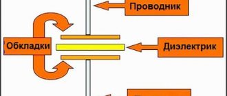
Capacitor device
The simplest capacitor consists of two metal plates (plates) separated by a dielectric layer. Capacitance (the ability to accumulate electrical charge) increases with increasing plate area and decreasing thickness of the insulating layer.
The parameters of the simplest design are too small. There are two ways to increase it:
- An increase in the area of the plates, which leads to an increase in dimensions.
- Reducing the thickness of the dielectric, leading to a decrease in the rated operating voltage due to electrical breakdown.
You might be interested in this: Features of a three-phase network
In order to avoid these problems, special designs have been developed. For example, if you make plates of small width and long length, they can be rolled together with a flexible dielectric into a dense cylinder, resulting in a cylindrical capacitor. By placing the dielectric plates alternately, in the form of a layer cake, and alternating connections to the terminals, a rectangular component with a large effective plate area is obtained.
Different types of construction
Another way is to use a thin oxide layer on the surface of a metal foil as a dielectric and a conducting electrolyte solution as a second plate. This produces an electrolytic capacitor whose design has the largest capacity.
Important! Such devices have the disadvantage of maintaining the polarity of the connection, which limits their use: it is only possible in DC circuits as smoothing filters.
AC circuit
In an AC circuit, a capacitor is a resistance. It quickly accumulates a certain charge and gradually releases it. Accumulation and full release occurs during a change in the electric wave.
DC circuit
In a DC circuit, charge accumulates on the plates, increasing the potential difference across the plates. The potential difference increases to the voltage value. As soon as it becomes equal to the voltage, the common circuit is broken.
Types of capacitors
To start powerful compressor engines, oil-filled non-polar capacitors are used.
The housing is filled with oil inside for good heat transfer to the surface of the housing. The body is usually metal or aluminum.
The most affordable capacitors of this type are CBB65.
To start less powerful loads, such as fan motors, dry capacitors are used, the housing of which is usually plastic.
The most common capacitors of this type are CBB60, CBB61.
The terminals are double or quadruple for ease of connection.
Types of capacitors
There are several types and types of capacitors. They are divided among themselves according to the following principle:
- Changing capacity. This change classifies electronic elements into constant, variable and interlinear.
- The dielectric material can be air, mica, Teflon, polycarbonate, or electrolyte.
- Installation. Based on the installation method, these radio components are divided into mounted and printed.
There are several types of capacitive devices, divided according to the principle of construction and performance:
- Ceramic. These elements are made of a disk with a conductor on both sides. Such printed parts have low operating voltage but high capacity.
- Film. Such capacitors have a film rolled into a roll inside the housing. A large charge and high operating voltage can be placed across all layers. The layers are made of foil with a dielectric on one side.
- Electrolytic. These devices are similar in structure to film devices. The difference is the dielectric material. For these printed elements, the dielectric is paper impregnated with electrolyte.
- Variables. These are devices for precise adjustment of instruments. The capacitance is changed mechanically.
- Interlinear. These are elements of one-time setting of parameters in devices. Such settings are performed only at manufacturing plants.
- Launchers. These capacitors are used to start electric motors. They operate on an alternating current circuit of 220 volts.
What is capacity?
If you remove a single electrical conductor infinitely far, eliminating the influence of charged bodies on each other, then the potential of the remote conductor will become proportional to the charge. But conductors of different sizes do not have the same potential.
The SI unit of capacitance for a capacitor is the farad. The proportionality coefficient is denoted by the letter C - this is the capacitance, which is affected by the size and external structure of the conductor. The material and phase state of the electrode substance do not play a role - the charges are distributed on the surface. Therefore, in the international GHS rules, capacity is measured not in farads, but in centimeters.
A solitary sphere with a radius of 9 million km (1400 Earth radii) contains 1 farad. A separate conductive element holds charges in quantities insufficient for technical use. According to technologies of the 21st century. a capacitance of capacitors with units of measurement higher than 1 farad is created.
A structure of at least 2 electrodes and a separating dielectric is capable of accumulating the amount of electricity required for the operation of electronic circuits. In this design, positive and negative particles are mutually attracted and support themselves. The dielectric between the electron-positron pair does not allow annihilation. This state of charge is called bound.
Previously, bulky equipment that was not very accurate was used to measure electrical quantities. Now even a novice radio amateur knows how to measure capacitance with a tester.
Measuring resistance
So, first you need to check the resistance of the capacitor with a multimeter. To do this, unsolder the barrel from the diagram and, using tweezers, carefully move it to a work surface, for example, a free table.
After this, we switch the tester to the continuity mode (resistance measurement) and touch the leads with the probes, observing the polarity.
Please note that if you confuse a minus with a plus, the performance check may fail, because the capacitor will immediately fail. To prevent this from happening, remember the following point - manufacturers always mark the negative contact with a tick!
To prevent this from happening, remember the following point - manufacturers always mark the negative contact with a tick!
After you touch the legs with the probes, the first value should appear on the display of the digital multimeter, which will immediately begin to increase. This is due to the fact that the tester will begin to charge the capacitor upon contact.
After some time, the maximum value “1” will appear on the display, which indicates the serviceability of the part.
If you just started checking the capacitor with a multimeter, and you get a “1”, it means there is a break inside the barrel and it is faulty. At the same time, the appearance of a zero on the display indicates that a short circuit has occurred inside the condenser.
If you decide to use an analog multimeter (pointer) to check the resistance, then it will be even easier to determine the performance of the element by observing the movement of the arrow. As in the previous case, the minimum and maximum values will indicate a breakdown of the part, and a smooth increase in resistance will indicate the suitability of the polar capacitor.
To independently check the integrity of a non-polar conductor at home, it is enough to touch the tester’s probes to the legs without observing polarity, setting the measuring range to 2 MOhm. A value greater than two should appear on the display. If this is not the case, the capacitor is not working and needs to be replaced.
It should also be noted that the verification method provided above is only suitable for products with a capacity of more than 0.25 µF. If the value of the circuit element is lower, you must first make sure that the multimeter is capable of operating in this mode, or buy a special tester - an LC meter.
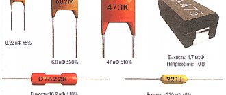
Markings on capacitors
Knowledge of the characteristics of electronic devices is required for accurate and safe operation.
Determining the capacitance of a capacitor involves measuring the value with instruments and reading the markings on the case. The indicated values and those obtained during measurements differ. This is caused by imperfect production technologies and operational variations in parameters (wear, temperature influence).
The body indicates the nominal capacity and parameters of permissible deviations. In household devices, devices with a deviation of up to 20% are used. In the space industry, military equipment and automation of dangerous objects, a spread of characteristics of 5-10% is allowed. Work plans do not contain tolerance values.
The rated capacity is coded according to IEC standards - the International Electrotechnical Commission, which unites national standards organizations in 60 countries.
The IEC standard uses the notation:
- 3 digit encoding. 2 signs at the beginning - the number of pF, the third - the number of zeros, 9 at the end - the value is less than 10 pF, 0 at the front - no more than 1 pF. Code 689 - 6.8 pF, 152 - 1500 pF, 333 - 33000 pF or 33 nF, or 0.033 µF. To make it easier to read, the decimal point in the code is replaced by the letter "R". R8=0.8 pF, 2R5 - 2.5 pF.
- 4 digits in marking. The last one is the number of zeros. The first 3 are the value in pF. 3353 - 335000 pF, 335 nF or 0.335 µF.
- Using letters in code. The letter µ is μF, n is nanofarad, p is pF. 34p5 - 34.5 pF, 1µ5 - 1.5 µF.
- Planer ceramic products are coded with the letters AZ in 2 registers and a number indicating the power of 10. K3 - 2400 pF.
- Electrolytic SMD devices are marked in 2 ways: numbers - the rated capacity in pF and next to it or in the 2nd line if there is space - the value of the rated voltage; a letter encoding the voltage and next to it there are 3 numbers, 2 determine the capacity, and the last one - the number of zeros. A205 means 10 V and 2 µF.
- Surface mount products are marked with a code of letters and numbers: CA7 - 10 µF and 16 V.
- Encodings - by body color.
IEC markings, national designations and brand codes make memorizing codes pointless. Hardware developers and repairmen need reference sources.
We check the capacitor with a multimeter in ohmmeter mode
For example, we will test four capacitors: two polar (dielectric) and two non-polar (ceramic).
But before checking, we must definitely discharge the capacitor; in this case, it is enough to close its contacts using any metal.
In order to switch to resistance (ohmmeter) mode, we move the switch to the resistance measurement group in order to determine the presence of an open or short circuit.
So, first of all, let’s check the polar conditioners (5.6 µF and 3.3 µF) previously installed in non-working energy-saving light bulbs
We discharge the capacitors by shorting their contacts with a regular screwdriver. You can use any other metal object that is convenient for you. The main thing is that the contacts fit tightly to it. This will allow us to get accurate readings from the device.
The next step is to set the switch to the 2 MOhm scale and connect the contacts of the capacitor and the probes of the device. Next, we observe rapidly changing resistance parameters on the display.
You ask me, what’s the matter and why do we see “floating indicators” of resistance on the display? This is quite simple to explain, since the power supply to the device (battery) has a constant voltage and due to this the capacitor is charged.
Over time, the capacitor accumulates more and more charge (charges), thereby increasing its resistance. The capacitor capacity affects the charging speed. As soon as the capacitor is fully charged, its resistance value will correspond to infinity, and the multimeter will show “1” on the display. These are the parameters of the working capacitor.
There is no way to show the picture in the photo. So for the next instance with a capacity of 5.6 μF, the resistance indicators start at 200 kOhm and gradually increase until they overcome the 2 MOhm indicator. This procedure does not take more than -10 seconds.
For the next capacitor with a capacity of 3.3 μF, everything happens similarly, but the process takes less than 5 seconds.
You can check the next pair of non-polar capacitors in the same way as with the previous capacitors. We connect the probes of the device and the contacts, monitor the state of the resistance on the device display.
Let's look at the first “150nK”. Initially, its resistance will decrease slightly to approximately 900 kOhm, then it will gradually increase to a certain point. The process takes 30 seconds.
At the same time, on the MBGO model multimeter, set the switch to the 20 MOhm scale (the resistance is decent, charging is very fast)
The procedure is classic, we remove the charge by closing the contacts with a screwdriver:
We look at the display, tracking the resistance indicators:
We conclude that as a result of the check, all the presented capacitors are in working order.
Calculation using formulas
Calculation of the nominal capacity of an element is required in 2 cases:
- Electronic equipment designers calculate the parameter when creating circuits.
- In the absence of capacitors of suitable power and capacity, craftsmen use element calculations to select from available parts.
RC circuits are calculated using the value of impedance - complex resistance (Z). Ra - current losses due to heating of circuit participants. Ri and Re — take into account the influence of inductance and capacitance of the elements. At the resistor terminals in the RC circuit, the voltage Uр is inversely proportional to Z.
Thermal resistance increases the potential across the load, and reactive resistance decreases. Operating a capacitor at frequencies above resonant frequencies, when the reactive component of the complex resistance increases, leads to voltage losses.
The resonance frequency is inversely proportional to the ability to accumulate charge. From the formula for determining Fр, they calculate what values of C (capacitor capacitance) are required for the operation of the circuit.
To calculate pulse circuits, the circuit time constant is used, which determines the effect of RC on the pulse structure. If the circuit resistance and capacitor charging time are known, the capacitance is calculated using the time constant formula. The truth of the result is influenced by the human factor.
Craftsmen use parallel and series connections of capacitors. The calculation formulas are the reverse of the formulas for resistors.
A series connection makes the capacitance smaller in the connection of elements; a parallel circuit adds up the values.
DIY device
To test capacitors, you can assemble your own device. It will determine the capacity no worse than professional equipment. Assembling such a device with your own hands is quite simple. Using this device you can check the performance of any capacitive elements and even SMD.
The device will require the following parts:
- A microcircuit from the 555 series, for example, NE555 or the domestic analogue KR1006VI1. This microcircuit is a time timer, but in the device it will play the role of a generator.
- Resistors: R1 and R5 for 6.8 K. R12 for 12 K. R10 for 100 K. R2 and R6 for 51 K. R13 and R11 for 100 K. R3 and R7 for 68 K. R14 for 120 K. R4 and R8 for 510 K. R15 at 13 K.
- Capacitors: C1 with a capacity of 47nf, C2 with a capacity of 470pf, C3 with a capacity of 0.47 mkF.
- VD1 is suitable for any low power diode, for example, SOD 232.
- SA1 is any 5 position switch.
- Multimeter X1.
- Battery or power supply up to 12 volts.
The operating principle of the device is as follows:
- Resistors R1 and R8, together with capacitors C1 and C2, create rectangular pulses, which are adjusted using switch SA1. The device operates in the frequency range from 25 and 2.5 kHz and 25–250 Hz.
- The charge for the element under test is supplied through the diode VD1.
- The charge dischargers are resistors R10, 12, 15.
- The resulting discharge pulse is calculated by the 555 microcircuit. The pulse duration is equal to the capacitance of the element under test.
- Resistor R13 and capacitor C3, located at the output, convert the pulse into electric current. The voltage is equal to the capacitance of the radio component under test.
- The output voltage is supplied to the X1 multimeter, which shows the number of volts, and therefore the total capacity of the part.
Using this device, you can test capacitors with capacities from 20 pF to 200 mkF. The circuit is assembled on a printed circuit board, which must be cleared of all old tracks and etched. If the circuit is assembled by soldering with wires, it must be taken into account that the length of the wire greatly affects the pulse length.
Schematic diagram on the printed circuit board:
Difficulties of verification
The process of determining the capacitance of a capacitor directly on the board is complicated by the presence of other circuit components - they distort the readings of the device.
First of all, this applies to elements with low resistance to direct current: fuses, inductors, transformer windings.
Determining the capacitance of a capacitor without soldering is possible only in the absence of the mentioned components.
Semiconductor devices - diodes and transistors - also have an effect.
When checking a capacitor for breakdown by measuring resistance, the multimeter will display the resistance of the Pn junction instead of infinity (on the display “1”). As a result, the state of the capacitor will remain unknown.
Checking the capacitor at home using a multimeter + video
The process of checking a capacitor with a multimeter
To test capacitors, special devices are often used - multimeters.
First you need to measure the resistance of the device, for this:
- Disconnect the capacitor barrel from the circuit;
- Touch the probes of the device to the legs of the capacitor, without reversing the polarities. The “minus” on the capacitor is indicated by a white stripe along the entire length of the device;
Visual image of a light stripe on a capacitor
The following video will describe the process of checking the capacitor in more detail.
Check Features
The capacitor is checked for serviceability using various methods. The main method is by desoldering it from the circuit. Sometimes you can check the functionality without soldering. But the results of the study will not be accurate - it is influenced by other components. To check the circuit, testers with tiny voltages on the probes are used. Low voltage prevents damage to other components of the board.
Regardless of the features of the models, all electrolytic capacitors have high power. When the test is performed, they are recharged. Its duration is only a few seconds. During the charging process, an increase in the resistance level is observed, with the movement of the tester needle or a change in the digital indicators in the electronic multimeter.
Polar capacitors
These electrolytic conductors are polarized. When connecting to the network, it is necessary to check the correct connection. We connect pluses with pluses, and minuses with minuses. Ignoring this rule leads to an explosion of the electrolyte.
Electrolyte can be solid or liquid. The capacitance of the elements is 0.1–100000 μF. The purpose of the elements is signal alignment and filtering. Marks “-” and “+” are marked on the body. The positive lead is longer. When the polarity is reversed, a breakdown of the dielectric occurs, as a result of which the electrolyte instantly evaporates and the housing ruptures. The dielectric is paper impregnated with electrolyte. Modern buildings are pressed in at the top and cut with a cross. During an explosion, not the whole thing disintegrates, but only the upper part. Taking into account the specially weakened elements, in the event of a malfunction, swelling of the upper part is visible.
Non-polar capacitors
It is easy to visually distinguish non-polar from polar - it will not have polarity markings on the body. Non-polar ones have a different dielectric material. Consists of ceramics or glass. The self-discharge current is much lower, given the higher dielectric resistance than paper. The higher the resistance of the dielectric partition, the lower the leakage current.
It is not at all necessary to observe polarity when connecting to the circuit. Sometimes such conductors are made very small and included in the circuit in large quantities.
The capacity of the parts is small - from microfarads to picofarads.
ESR electrolytic capacitors
Basically, the ESR parameter concerns electrolytic capacitors. The electrolyte that is there loses some of its properties when heated and the capacitor changes its capacity, which, of course, is undesirable. After decent heating, the capacitor begins to dull, swells and quickly ages.
For swollen capacitors, it is the ESR that first of all increases, while the capacitance can remain practically nominal until a certain time (well, the one that is written on the capacitor itself)
Most often they swell in switching power supplies and on motherboards, usually near the processor (the load on them is higher there, and the heat from the processor probably plays a role). One of the characteristic symptoms: equipment (computer, monitor) begins to turn on worse and worse. Either with a pause (up to several hours after turning on the network), or on the tenth attempt.
Another symptom: if you turn off the power for a while (turn off the power filter, or unplug it from the socket), it starts to turn on again, not on the first try, or after a pause. And if you do not turn off the power, then the computer can turn on immediately (but this is also for the time being, of course). But it happens that the capacitors are not swollen, and the ESR is already tens of times higher than normal. Then, of course, we replace it. From experience, this is a very common problem. And very easily diagnosed (especially if you have a miracle device from your Chinese comrades).
How to test a capacitor with a multimeter
The industry produces several types of testing equipment for measuring electrical parameters. Digital ones are more convenient for measurements and give accurate readings. Arrow people prefer the visual movement of arrows.
If the conder appears to be absolutely intact, it is impossible to check it without instruments. It is better to carry out the check by desoldering it from the circuit. This way the indicators are read more accurately. Simple parts rarely fail. Dielectrics are often damaged mechanically. The main characteristic during testing is the passage of only alternating current. The constant passes exclusively at the very beginning for a short period of time. The resistance of the part depends on the existing capacitance.
The prerequisite for testing a polar electrolytic capacitor with a multimeter for performance is a capacity of more than 0.25 μF. Step-by-step verification instructions:
- Discharging the element. To do this, its legs are short-circuited with a metal object. A short circuit is characterized by the appearance of a spark and sound.
- The multimeter switch is set to the resistance value.
- Touch the legs of the capacitor with the probes, taking into account the polarity. Red to the positive leg, black to the negative leg. This is only necessary when working with a polarized device.
The capacitor begins to charge when the probes are connected. Resistance rises to its maximum. If the multimeter beeps when the probes are zero, it means a short circuit has occurred. If the value 1 is immediately displayed on the dial, then there is an internal break in the element. Such conductors are considered faulty - a short circuit and a break inside the element cannot be repaired.
If the value 1 appears after some time, the element is considered normal.
Testing a non-polar capacitor is even easier. On the multimeter we set the measurement to megaohms. After touching the probes, we look at the readings. If they turn out to be less than 2 MΩ, the part is faulty. More than that - serviceable. There is no need to observe polarity.
Electrolytic
As the name suggests, electrolytic conductors in an aluminum case are filled with electrolyte between the plates. The dimensions are very different - from millimeters to tens of decimeters. Technical characteristics can exceed those of non-polar ones by 3 orders of magnitude and reach large values - units of mF.
In electrolytic models, an additional defect appears associated with ESR (equivalent series resistance). This indicator is also abbreviated ESR. Such capacitors in high-frequency circuits filter the carrier signal from parasitic signals. But it is possible to suppress EMI by greatly reducing the level and playing the role of a resistor. This leads to overheating of the part structure.
What is ESR made up of:
- resistance of plates, leads, connections;
- inhomogeneity of dielectrics, moisture, parasitic impurities;
- electrolyte resistance due to changes in chemical parameters during heating, storage, and drying.
In complex circuits, the ESR indicator is especially important, but is measured only with special instruments. Some craftsmen make them themselves and use them in conjunction with conventional multimeters.
Ceramic
First, we inspect the device visually. Be especially careful if the circuit uses used parts. But new ceramic materials can also be defective. Conders with a breakdown are immediately noticeable - darkened, swollen, burnt, with a cracked body. Such electrical parts are definitely rejected even without instrumental testing - it is clear that they are inoperative or do not produce the assigned parameters. It is better to take care of searching for the causes of breakdowns. Even new copies with a crack in the body are a “time bomb.”
Film
Film devices are used in DC circuits, filters, and standard resonant circuits. The main malfunctions of low-power devices:
- decreased performance due to drying out;
- increase in leakage current parameters;
- increased active losses within the circuit;
- short circuit on the plates;
- loss of contact;
- conductor break.
It is possible to measure the capacitance of a capacitor in testing mode. Arrow models react by deflecting the arrow with a jump and returning to zero. With a slight deviation of the arrows, current leakage is diagnosed at low capacity.
Low efficiency with low power level and high leakage current prevents the widespread use of these capacitors and does not allow its full potential to be revealed. Therefore, the use of this type of condenser is impractical.
Using a tester for verification
It's time to answer the question of how to test a capacitor with a multimeter. First of all, we need to clarify right away: with a multimeter you can only check parts with a capacity of at least 0.25 μF and no more than 200 μF.
These restrictions are based on the principles of their operation, and in general the principle of the test itself - low-capacity ones will not have enough sensitivity of the device, and powerful ones, for example, a high-voltage capacitor, can damage both the device and the tester himself.
The fact is that any capacitor must be discharged before starting to measure capacitance or check for a short circuit. To do this, both of its terminals are connected to each other with any conductor - a piece of wire, a screwdriver, tweezers, and so on.
In this case, in the case of a weak element, a soft bang and a flash occur. But a powerful, for example, starting capacitor (especially a Soviet-made one, for starting fluorescent lamps) will give a flash comparable in power to an electric welding flash. The metal conductor may even be melted.
Therefore, it is necessary to use either a screwdriver or pliers with an insulated handle, or electrical rubber gloves. Otherwise, you may receive an electric shock.
How to check without desoldering
It is possible to ring the capacitor with a multimeter without desoldering. For such a check, we select a working specimen with similar characteristics and solder it into the circuit parallel to the one being tested. The working device will indicate a problem in the first element. The method is not applicable to high voltage circuits.
You can check a powerful starting capacitor with a multimeter without desoldering for the presence of a spark. The charged conductor is closed with a screwdriver or other tool with an insulated handle. A characteristic sound with a spark will indicate the functionality of the device.
It is not advisable to take measurements without special instruments. It is easy to get an electric shock on high-voltage samples, and the exact values cannot be determined.
First way
The first method is the simplest. The subject is checked by a tester and called with a multimeter. The device is put into resistance testing mode. It is also worth considering polarity. The multimeter probes are connected to the terminals of the capacitor and the resistance is measured. It is worth considering that the obtained value has no practical use, since it may be an indication of another element. In this way, you can check the capacitive part for a short circuit. If the values on the display begin to increase gradually, then the printed part is being charged by the tester and is in good condition.
Second way
The second method requires soldering a capacitor with the same values into the circuit next to the element under test. Soldering must be done in parallel. Both elements are measured on a de-energized board.
Important! Without soldering, you can only test parts that are part of low-voltage circuits. For high-voltage circuits, such testing is prohibited.
Third way
A situation often arises when there are several capacitors on the board, and it is very difficult to determine which one is faulty. Soldering each one is quite labor-intensive; they often fail when heated. In order to check without desoldering, it is necessary to measure the output voltage. It must be the same as indicated on the element body. If there is no voltage, then the part is broken or shorted. If the voltage is less than the optimal value, the element has lost part of its capacity.
Without desoldering, you can determine the faulty element visually. The capacitor may simply burst, have damage on the housing, carbon deposits or swelling.
Defining parameters
It’s very easy to check the element’s functionality yourself. Modern multimeters and testers have a corresponding function for this. The main parameter during testing will be the compliance of the declared and actual capacity, as well as the throughput of the radio component. The test can be carried out both on the board itself and by removing the part from the printed circuit board.
Capacity check
Often capacitors, especially old ones, have unclear capacitance markings on their housings. In order to find out the capacity of the working device, you need to use a multimeter that has a capacity measurement function. Modern multimeters have a measuring range from 20 nF to 200 mF. To determine the capacitance of an unmarked capacitor, you will have to test it in 5 modes: 20 nF, 200 nF, 2 mF, 20 mF, 200 mF. You will also have to take polarity into account if the element is polar. Before measurement, it is necessary to remove the capacitor from the circuit.
- The device switches to capacity test mode. Be sure to switch the probes to the cX socket.
- The element under test must be discharged before testing. This is done by shorting both ends.
- Both probes are connected to the terminals.
The resulting value is the nominal capacity.
Polarity Determination
To determine the polarity, you can visually inspect the housing. Definition of "+":
- Soviet capacitors had a “+” sign on the case on the side of one of the legs.
- Modern radio components are also marked on the housing with a “+” sign.
- SMD capacitors have a “+” sign on one side or are marked with a colored stripe.
The minus is also determined visually:
Modern capacitors have different body colors. On black or blue cases, the minus is indicated as a silver stripe or a blue arrow. SMD elements are marked with a blue or black stripe. Often on them the “+” side has a convexity, and the minus is simply flat at the end. New capacitors, even before installation, have a positive leg, which is much longer than the negative leg.
Visual inspection
Sometimes one glance is enough to identify a faulty capacitor on the board. In such cases, there is no point in checking it with any instruments. The capacitor must be replaced if a visual inspection shows the presence of:
- even slight swelling, traces of leaks;
- mechanical damage, dents;
- cracks, chips (relevant for ceramics).
Capacitors that have any of the above characteristics CANNOT be used.
Device with capacitance measurement function
In the settings panel of such models there is a “CX” sector. The measuring range is smaller than that of an LC meter (up to 200 µF), but it is sufficient for the most common elements.
The check is simple:
- the multimeter switch is set in the “CX” sector to the position with a numerical value that is closest to the expected capacitance;
- the capacitor leads are brought to the contact pads in the “CX” sector or they are touched with probes inserted into sockets with the same mark (depending on the model);
- The display will show the capacity.
Test results
Electrolytic capacitors are polarity sensitive. "CX" sockets and pads are marked with "+" and "-" symbols. The negative terminal of the capacitor is indicated by a tick.
Devices without capacitance measurement function
Such models are used in ohmmeter mode.
Procedure:
- the black probe is plugged into the “COM” socket (negative potential), the red one into the “V/Ω” socket (positive potential);
- the switch is set in the “Ω” sector to the 2 MOhm position;
- Observing polarity, touch the terminals with the probes.
In ohmmeter mode, the multimeter supplies voltage to the probes.
It charges the capacitor and the resistance of the latter, gradually increasing from minuscule to a value of over 2 MOhm or infinity (indicated by one on the display).
The increase in resistance is most objectively reflected by an analog (arrow) tester.
A malfunction is indicated by the behavior of the device when the resistance:
- immediately became infinite: the conclusion was cut off;
- stopped at below 2 MOhm: the capacitor is broken.
Based on the time during which the resistance increases from minimum to maximum, by comparison with known-good capacitors, you can approximately determine the capacitance of the test item.
This method is not suitable for testing capacitors with low capacitance - 20 µF and below. They charge quickly and even with a working element, the resistance almost immediately becomes infinite.
To test for reversible breakdown, the capacitor is connected to a laboratory DC source with a voltage regulator, and a multimeter in ammeter mode is connected in series with it. The voltage is gradually increased to the maximum permissible. If during this process the tester displays a non-zero current strength, then a reversible breakdown has occurred.
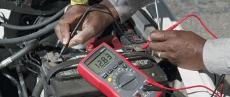
Checking without instruments
The procedure for testing the performance of energy storage devices without devices:
- From the contact on the distributor breaker we disconnect the wires coming from the capacitor and the ignition coil.
- We attach a test lamp or car indicator contacts between the wires.
- We turn on the ignition, the light comes on - this means that the part being tested is faulty and needs to be replaced.
Instead of points 2 and 3, under certain circumstances, you can turn on the ignition and connect the wires to each other; sparking will be a signal of a malfunction.
If your car has the ability to manually rotate the crankshaft, then you can try another way to check the capacitor.
Algorithm of actions:
- By rotating the crankshaft we achieve closure of the contacts in the distributor.
- Disconnect the flexible end of the capacitor from the breaker.
- Pull out the central wire from the distributor cap.
- Turn on the ignition and bring it to the disconnected contact of the drive.
- We open the breaker with a screwdriver or turn the distributor housing to do this; the spark that slips between the wires charges the capacitor with a high voltage current.
- We bring its flexible contact closer to the body, a discharge spark jumps with a click and indicates serviceability. If there is no spark or click, the part being tested must be replaced.
In some cases, a visual inspection may be sufficient.
During a routine inspection, the following faults may be detected:
- swelling or rupture of the body;
- traces of electrolyte leakage;
- change in body color;
- signs of thermal effects in the area where the capacitor is attached.
Determination of capacitor operating voltage
Strictly speaking, if there is no marking on the capacitor and the circuit in which it was installed is not known, then it is IMPOSSIBLE to find out its operating voltage using non-destructive methods.
However, having some experience, you can very roughly estimate the operating voltage based on the dimensions of the capacitor. Naturally, the larger the size of the capacitor and the smaller its capacity, the higher the voltage it is designed for.
Method No. 1: determining operating voltage through breakdown voltage
If there are several identical capacitors and you don’t mind sacrificing one of them, then you can determine the breakdown voltage, which is usually 2-3 times higher than the operating voltage.
The breakdown voltage of a capacitor is measured as follows. The capacitor is connected through a current-limiting resistor to an adjustable voltage source capable of delivering obviously more than the breakdown voltage. The voltage across the capacitor is controlled by a voltmeter.
Then the voltage is gradually increased until breakdown occurs (the moment when the voltage across the capacitor suddenly drops to zero).
The operating voltage can be taken to be 2-3 times less than the breakdown voltage. But this is... You can have your own opinion on this matter.
Attention! Be sure to follow all safety precautions! When checking a capacitor for breakdown, it is necessary to use a protected stand, as well as personal eye protection.
The energy of a charged capacitor is enough to cause a small nuclear explosion right on your desktop. Here you can see how it happens:
And some types of ceramic capacitors, during an electrical breakdown, can shatter into very small but hard fragments that can easily pierce the skin (not to mention the eyes).
Method No. 2: finding the operating voltage of the capacitor through the leakage current
This method of finding out the operating voltage of a capacitor is suitable for aluminum electrolytic capacitors (polar and non-polar). And the majority of such capacitors.
The point is to catch the moment at which its leakage current begins to increase nonlinearly. To do this, we put together the simplest diagram:
and measure the leakage current at various values of the applied voltage (from 5 volts onwards). The voltage should be increased gradually, in equal portions, recording the readings of the voltmeter and microammeter in the table.
I ended up with a sign like this (my instincts told me that this was a fairly high-voltage capacitor, so I immediately started adding 10V at a time):
Voltage on the capacitor, VT Leakage current, µA Increase in current, µA
| 10 | 1.1 | 1.1 |
| 20 | 2.2 | 1.1 |
| 30 | 3.3 | 1.1 |
| 40 | 4.5 | 1.2 |
| 50 | 5.8 | 1.3 |
| 60 | 7.2 | 1.4 |
| 70 | 8.9 | 1.7 |
| 80 | 11.0 | 2.1 |
| 90 | 13.4 | 2.4 |
| 100 | 16.0 | 2.6 |
As soon as it becomes noticeable that the same increase in voltage each time leads to a disproportionately larger increase in the leakage current, the experiment should be stopped, since we are not faced with the task of bringing the capacitor to an electrical breakdown.
If you build a graph from the obtained values, it will look like this:
It can be seen that starting from 50-60 volts, the graph of the leakage current versus voltage becomes clearly nonlinear. And if we take into account the standard range of voltages:
Standard range of rated operating voltages of capacitors, V
| 6.3 | 10 | 16 | 20 | 25 | 32 | 40 | 50 | 63 | 80 | 100 | 125 | 160 | 200 | 250 | 315 | 350 | 400 | 450 | 500 |
then we can assume that for a given capacitor the operating voltage is either 50 or 63 V.
I agree that the method is quite labor-intensive, but not mentioning it would be a mistake.
Low ESR Capacitors
In our rapidly developing world, electronics are increasingly built on the RF part. Switching power supplies have almost completely triumphed over bulky transformer power supplies. We, radio amateurs, still use homemade power supplies made from transformers that we found in the trash.
But since almost all equipment goes into the HF range, then the developers of radio components do not sleep either. They create capacitors that have low ESR and are called LOW ESR , which means low ESR capacitors. On some they write this right on the body:
A distinctive feature of such capacitors is that they are elongated. Also, according to my observations, they most often have a gold stripe:
Nowadays, miniature polymer aluminum capacitors with low ESR are increasingly used:
Where can you most often see them? Of course, by disassembling your personal computer. You can find them in the power supply, as well as on the computer motherboard.
In the photo below we see a computer motherboard, which is completely covered with capacitors with LOW ESR, some of which I marked in the red rectangle:
Ceramic and SMD-ceramic capacitors have the smallest ESR
Interesting video on the topic:
How to measure capacitor leakage current?
The method for measuring leakage current has already been described a little higher. I would just like to add that Iut is measured either at the maximum operating voltage of the capacitor or at the voltage at which the capacitor is planned to be used.
You can also calculate the leakage current of a capacitor by an indirect method - through the voltage drop across a previously known resistance:
When checking polarized capacitors for leakage, it is necessary to observe the polarity of their connection. Otherwise, incorrect results will be obtained.
When measuring the leakage current of electrolytic capacitors after applying voltage, it is very important to wait some time (5-10 minutes) so that all electrochemical processes are completed. This is especially true for capacitors that have been out of service for a long time.
Using the "Cx" mode
After the contacts have been short-circuited, resistance can be determined. If the element is fixed, then immediately after connecting it will begin to charge with direct current. In this case, the resistance will appear minimal and will continue to grow.
If the capacitor is faulty, the multimeter will immediately indicate infinity or will indicate zero resistance and beep at the same time. This check is carried out if the structure is polar.
In order to find out the capacitance, you must have a multimeter with the function of measuring the “Cx” parameter.
Determining capacitance using such a multimeter is simple: set it to “Cx” mode and indicate the minimum measurement limit that a given capacitor should have. Such multimeters have special sockets with certain measurement limits. A capacitor is inserted into these sockets according to its measurement limit and its parameters are determined.
If the tester does not have such sockets, then you can determine the capacitance using measuring probes, as shown in the photo below:
Important! In a separate article we talked about how to check the health of a capacitor. We also recommend that you read this material!
Inspection Precautions
Discharging the capacitor is mandatory. This is especially true for high-voltage parts - they can damage the multimeter or shock a person. Discharge by touching the legs with a metal object or connecting a lamp. The second method makes the discharge process smoother.
During measurement, do not touch the open parts of the probe with your hands - the human body has low resistance and a high leakage rate. In this case, the measurement will be incorrect. The current will follow the path of least resistance and the readings will show a value that has nothing to do with the capacitor.
Measurements on high-voltage capacitors are carried out using rubber gloves and insulated instruments.
A properly functioning electronic component is capable of storing and releasing a certain amount of electricity. Breakdowns during operation are determined not only visually, but also using a multimeter. Testing with a measuring device can clarify the suitability of an element for further use.
Checking the health of capacitors
Modern multimeters are capable of measuring and checking the performance of any radio components. But this device is not always at hand. You can check the capacitor using a tester.
Multimeter
If the multimeter has a special function for measuring capacitance, then it can be used to test any type of device. Ceramic, electrolytic, and starting radio components have the same operating principle, which means that serviceability checks can be carried out in the same way.
- Unsolder the part under test from the board and discharge it by closing the contacts.
- Set the multimeter to the “cX” capacitance detection mode.
- Switch the device to determine the maximum capacity range.
- Connect the probes to the legs or terminals of the capacitor.
- The multimeter will show the capacitance value. If one or more “0”s are displayed before the value, the device switches to a lower parameter.
Polarized capacitors (if the polarity is correct) show gradually increasing values from “0” to “1”. If the display shows “1” without changes, then the capacitor is not working. If the readings are “0”, then the element is closed internally.
Non-polar capacitors are checked by setting the multimeter to 2 MΩ. If the readings are higher than this value, then the device is working properly. Values less than 2 MΩ indicate a malfunction.
Tester
You can check the capacitor using a tester only to determine its general serviceability. Capacitance loss or voltage variation cannot be determined.
- To check, you need to set the tester to resistance mode.
- Unsolder and discharge the element being tested.
- If the radio component is polar, you need to connect the tester terminals to the terminals according to the polarity.
- Polar capacitors (having a large capacity) will charge for a few seconds, non-polar ones will show their value immediately.
Polarized capacitors should show a slowly rising value of more than 100 kOhm. If this value is lower, the capacitor is faulty.
Non-polar ones will show a value of 1 ohm. If the value equal to “1” is reached instantly, then the capacitor is faulty. A value of “0” indicates an internal short circuit.
Basic capacitor malfunctions
Capacitive elements play a large role in the circuit diagram of any device. Their main function is to charge a certain amount of current and pulse discharge into the circuit. The main malfunctions of capacitors include:
- Normal breakdown. A breakdown can be caused by an increase in operating voltage. Repair requires not only replacing the element, but also determining the cause of the high voltage.
- Internal break. If a radio component breaks, it loses its capacity, since both of its outputs become isolated. A break can occur when the device is dropped or the element itself is poorly assembled.
- A leak. This problem is due to the loss of some capacity. The smaller the permissible and optimal capacity, the smaller the charge size.
Sources
- https://ProFazu.ru/provodka/instruments/pribor-dlya-proverki-kondensatorov.html
- https://rusenergetics.ru/polezno-znat/v-chyom-izmeryaetsya-yomkost-kondensatora
- https://MasterXoloda.ru/1/proverka-i-zamena-puskovogo-i-rabochego-kondensatorov
- https://odinelectric.ru/equipment/electronic-components/kak-izmerit-yomkost-kondensatora-multimetrom
- https://proprovoda.ru/instrument/izmeritelnyj/multimetr/kak-proverit-kondensator-multimetrom-ne-vypaivaya.html
- https://TehnoPanorama.ru/instrumenty/kak-proverit-kondensator-multimetrom.html
- https://proprovoda.ru/elektrooborudovanie/kak-proverit-elektroliticheskij-kondensator.html
- https://electro-shema.ru/remont/kak-proverit-kondensator.html
[collapse]