Start and stop buttons
When starting and stopping the engine using a starter, it is convenient to connect a device with buttons connected in series with the device.
To ensure that the engine does not stop working after pressing the “start” button, self-retaining is introduced into the circuit due to the terminals paralleled with the “start”. Thanks to them, the engine runs after the “start” button is no longer pressed, until the stop button is pressed.
Voltage is supplied to the motor through any contact marked with the letter L, and it is removed from the corresponding contact under the letter T. This connection diagram is valid for a single-phase network.
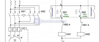
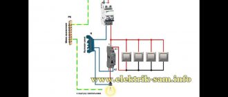
Connecting a magnetic starter via a push-button post
This circuit includes additional start and stop buttons. Both “Stop” buttons are connected in the control circuit in series, and the “Start” buttons are connected in parallel. This connection allows switching with buttons from any position.
Here's another option. The circuit consists of a two-button post “Start” and “Stop” with two pairs of contacts, normally closed and open. Magnetic starter with a control coil for 220 V. The power supply for the buttons is taken from the terminal of the power contacts of the starter, number 1. The voltage approaches the “Stop” button, number 2. It passes through a normally closed contact, along the jumper to the “Start” button, number 3.
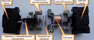
Magnetic starter design
The picture below shows the components of a typical starter. The stationary lower part, when the coil is connected to the power supply, forms an electromagnetic field that attracts the moving element. The contacts connected to the armature close the operating circuit. If the winding is de-energized, the spring will return the system to its original state.
Main functional elements of the starter
The core of the electromagnet is assembled from plates in the shape of the letter “W”. A large number of components block parasitic currents (skin effect). The number of turns is selected taking into account the supply voltage.
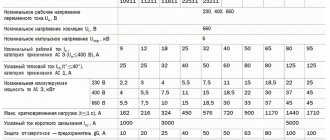
Sectors with designations
Explanatory inscriptions on the body are divided into three groups:
- general information and scope (AS1-4);
- information about permissible currents in load circuits (conversion to kW or reverse is performed taking into account the mains voltage);
- graphic designation of contact groups (the broken line indicates synchronous switching).
Each area can be explored in detail. To familiarize yourself with the classification by purpose categories, follow the standards of GOST R 50030.4.1.-2002. The designation AC1 indicates the possibility of connecting the starter to heating elements, incandescent lamps and other loads with weakly expressed reactive characteristics. If you need to ensure the start of a powerful engine, choose a model of the AC3 category.
Contact attachment
This part is mounted on a 220V electromagnetic starter to expand the basic functions:
- activation of reverse engine mode;
- additional load management;
- turning on the light indication.
For your information. A typical attachment mechanism contains two pairs of contacts. Rigid fixation of the block in a certain place is ensured by the special shape of the protrusions of the docking platform. When choosing the appropriate model, you should take into account the compliance with the starter, as well as the normally closed/open state of the contact group.
Contact groups of starters
According to current standards, input and output terminals are marked with the Latin letters L and T, respectively. In reality, taking turns doesn't matter. You can connect paired contacts to the power source and load in any combination. This is the main difference from a relay, where a permanent connection is created with one of the power supply circuits.
Important! It is recommended to follow standard standards so as not to complicate troubleshooting in the circuit and installation work. A separate contact group (13H0, 14H0) is designed for the operation of an independent “pickup” circuit. In this mode, the push-button start is activated by pressing once without holding
In this mode, the push-button start is activated by pressing once without holding
A separate contact group (13H0, 14H0) is designed for the operation of an independent “pickup” circuit. In this mode, the push-button start is activated by pressing once without holding.
Stop button
The control circuit of any starter is organized using two buttons without fixing the on position. “Stop” is indicated in red to enhance safety. In an emergency, this clear identification speeds up the disconnection of the power source.
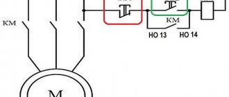
Starter connection diagram
In the initial position of the “Stop” button, the circuit is closed. When pressed, the induction coil is disconnected from the current source. The electromagnetic field disappears. The spring returns the armature to its original state while simultaneously opening the main contact group. The secondary closure of the circuit in this section does not matter, since the general break is provided by the “Start” button.
For your information. It should be emphasized that modern starters are compact. Such products are suitable for mounting on a standard DIN rail.
Start button
This control element is produced in black (green) color. In the initial state, the contacts are open. Pressing activates the formation of a magnetic field and the movement of the main contact group. “Self-recovery” ensures the functionality of the working power circuit after the start button is returned to its initial position.
Tips for installing magnetic starters
When installing magnetic starting devices with thermal relays, it is necessary to install with a minimum difference in ambient temperatures between the electric motor and the magnetic starting device.
It is undesirable to install magnetic devices in places subject to strong shocks or vibrations, as well as near powerful electromagnetic devices whose currents exceed 150 A, since they create quite large shocks and jolts when triggered.
For normal operation of the thermal relay, the ambient temperature should not exceed 40 0 C. It is also not recommended to install it near heating elements (rheostats) and not install them in the most heated parts of the cabinet, for example at the top of the cabinet.
Comparison of magnetic and hybrid starters:
Magnetic starters
They are mainly used for starting, stopping and reversing three-phase asynchronous electric motors, however, due to their unpretentiousness, they work perfectly in remote control circuits for lighting, in control circuits for compressors, pumps, crane beams, heating furnaces, air conditioners, belt conveyors, etc. d. In short, a magnetic starter has a wide range of applications.
As such, magnetic starters are already difficult to find in stores, since they have practically been replaced by contactors
. Moreover, in terms of its design and technical characteristics, a modern contactor is no different from a magnetic starter, and they can only be distinguished by name. Therefore, when you purchase a starter in a store, be sure to specify whether it is a magnetic starter or a contactor.
We will look at the design and operation of a magnetic starter using the example of a KMI
– small-sized AC contactor for general industrial use.
How does it work
In most cases, the above problems are successfully solved by using electromagnetic contactors. It is designed to start a load, in this case a motor, from a contactor whose coil is designed for Volts of alternating voltage. Sometimes the device begins to hum and create an increased noise level. With this scheme, the rated voltage of the coil is of great importance. There are no changes in phase A.
Pressing the power button closes the coil circuit. For this purpose, a circuit with a neutral conductor is used. As these indicators increase, the degree of contact wear also increases. But since a similar operating algorithm is suitable for many devices, a wide variety of devices are connected through them - lighting circuits, various devices and devices. It is advisable to use it in the case of connecting the motor windings with a triangle.
How to connect a 3-phase contactor with starter winding V? Automatic activation of the contactor is also possible; for these purposes, the button is replaced or duplicated by parallel activation of limit switches or sensors. Depending on the design, it can be designed for different voltages, both direct and alternating current.
Search on the site
The fourth X character indicates the number of additional contacts.
To avoid this, you should not select areas subject to vibration, shock, or shock. To understand how to connect a magnetic starter, let’s draw a combined diagram showing the details: In our case, we use a single-phase power source V, spaced control buttons, a protective thermal relay, and the magnetic starter itself. Conclusions and useful video on the topic Details about the design and connection of the contactor: Practical help in connecting the MP: Using the diagrams given, you can connect the magnetic starter with your own hands both to the network and to V. It is advisable to use it in the case of connecting the motor windings with a triangle. It is used in cases where it is necessary to carry out normal starting of an electric motor.
The third character X indicates the specific configuration of the contactor. Its shape is either U- or W-shaped, depending on the design of this switching product. Magnetic starter control circuits
The operating principle of the 380V electromagnetic starter connection diagram
In modern power engineering, electromagnetic starters are widely used.
These are devices designed to repeatedly turn electrical devices on and off.
The task of the device in question is to close and open contacts of electrical circuits of different power, at voltages up to 440 V DC and 600 V AC.
In their design they have:
- a certain set of working contacts designed to supply voltage to the power plant;
- auxiliary contacts - intended for control and signal circuits.
Connection diagrams
Let's start by looking at the design of a three-phase electric motor. Here we will be interested in three windings, which create a magnetic field that rotates the motor rotor. That is, this is exactly how the transformation of electrical energy into mechanical energy occurs.
There are two connection schemes:
Let’s immediately make a reservation that a star connection makes the unit start-up smoother. But at the same time, the power of the electric motor will be lower than the rated one by almost 30%. In this regard, the triangle connection wins. The motor connected in this way does not lose power. But there is one nuance that concerns the current load. This value increases sharply at start-up, which negatively affects the winding. High current in copper wire increases thermal energy, which affects the wire's insulation. This can lead to breakdown of the insulation and failure of the electric motor itself.
I would like to draw your attention to the fact that a large amount of European equipment imported to the vast expanses of Russia is equipped with European electric motors that operate at 400/690 volts. By the way, below is a photo of the nameplate of such a motor.
So, these three-phase electric motors must be connected to the domestic 380V network only in a triangle diagram. If you connect a European motor with a star, it will immediately burn out under load. Domestic three-phase electric motors are connected to a three-phase network according to a star circuit. Sometimes the connection is made in a triangle; this is done in order to squeeze out the maximum power from the motor, which is necessary for some types of technological equipment.
Manufacturers today offer three-phase electric motors, in the connection box of which the ends of the windings are made in the amount of three or six pieces. If there are three ends, this means that a star connection diagram has already been made inside the motor at the factory. If there are six ends, then the three-phase motor can be connected to a three-phase network with both a star and a delta. When using a star circuit, it is necessary to connect the three ends of the beginning of the windings in one twist. Connect the other three (opposite) to the phases of the three-phase 380 volt supply network. When using a triangle diagram, you need to connect all the ends together in order, that is, in series. The phases are connected to three points connecting the ends of the windings to each other. Below is a photo showing two types of connecting a three-phase motor.
Star-delta circuit
This connection scheme to a three-phase network is used quite rarely. But it exists, so it makes sense to say a few words about it. What is it used for? The whole point of such a connection is based on the position that when starting an electric motor, a star circuit is used, that is, a soft start, and for the main work a triangle is used, that is, the maximum power of the unit is squeezed out.
True, such a scheme is quite complicated. In this case, three magnetic starters must be installed in the connection of the windings. The first one is connected to the supply network on one side, and on the other side the ends of the windings are connected to it. The opposite ends of the windings are connected to the second and third. The second starter is connected with a triangle, and the third with a star.
Attention! The second and third starters cannot be turned on at the same time. A short circuit will occur between the phases connected to them, which will reset the machine. Therefore, a block is established between them
Essentially, everything will happen like this - when one is turned on, the contacts of the other open
Therefore, a block is established between them. Essentially, everything will happen like this - when one is turned on, the contacts of the other open.
The operating principle is as follows: when the first starter is turned on, the temporary relay also turns on starter number three, that is, connected according to the star circuit. The electric motor starts smoothly. The time relay is activated for a certain period during which the motor will return to normal operation. After which starter number three is turned off, and the second element is turned on, transferring the triangle to the circuit.
Connecting the motor via starters
Irreversible magnetic starter
If it is not necessary to change the direction of rotation of the engine, then the control circuit uses two non-fixed spring-loaded buttons: one in the normal position is open - “Start”, the other is closed - “Stop”. As a rule, they are manufactured in a single dielectric housing, and one of them is red. Such buttons usually have two pairs of contact groups - one normally open, the other closed. Their type is determined during installation work visually or using a measuring device.
The control circuit wire is connected to the first terminal of the closed contacts of the Stop button. Two wires are connected to the second terminal of this button: one goes to any of the closest open contacts of the “Start” button, the second is connected to the control contact on the magnetic starter, which is open when the coil is turned off. This open contact is connected by a short wire to the controlled terminal of the coil.
The second wire from the “Start” button is connected directly to the terminal of the retractor coil. Thus, two wires must be connected to the controlled “pull-in” terminal – “direct” and “blocking”.
At the same time, the control contact closes and, thanks to the closed “Stop” button, the control action on the retractor coil is fixed. When the Start button is released, the magnetic starter remains closed. Opening the contacts of the “Stop” button causes the electromagnetic coil to be disconnected from the phase or neutral and the electric motor is turned off.
Reversing magnetic starter
To reverse the motor, two magnetic starters and three control buttons are required. Magnetic starters are installed next to each other. For greater clarity, let’s conditionally mark their supply terminals as 1–3–5, and those to which the motor is connected as 2–4–6.
For a reversible control circuit, the starters are connected as follows: terminals 1, 3 and 5 with the corresponding numbers of the adjacent starter. And the “output” contacts are crosswise: 2 from 6, 4 from 4, 6 from 2. The wire feeding the electric motor is connected to three terminals 2, 4, 6 of any starter.
With a cross connection scheme, simultaneous operation of both starters will result in a short circuit. Therefore, the conductor of the “blocking” circuit of each starter must first pass through the closed control contact of the adjacent one, and then through the open one of its own. Then turning on the second starter will cause the first one to turn off and vice versa.
Not two, but three wires are connected to the second terminal of the closed “Stop” button: two “blocking” and one supplying the “Start” button, connected in parallel to each other. With this connection scheme, the “Stop” button turns off any of the connected starters and stops the electric motor.
Connection diagrams
Let's start by looking at the design of a three-phase electric motor. Here we will be interested in three windings, which create a magnetic field that rotates the motor rotor. That is, this is exactly how the transformation of electrical energy into mechanical energy occurs.
There are two connection schemes:
Let’s immediately make a reservation that a star connection makes the unit start-up smoother. But at the same time, the power of the electric motor will be lower than the rated one by almost 30%. In this regard, the triangle connection wins. The motor connected in this way does not lose power.
But there is one nuance that concerns the current load. This value increases sharply at start-up, which negatively affects the winding. High current in copper wire increases thermal energy, which affects the wire's insulation. This can lead to breakdown of the insulation and failure of the electric motor itself.
I would like to draw your attention to the fact that a large amount of European equipment imported to the vast expanses of Russia is equipped with European electric motors that operate at 400/690 volts. By the way, below is a photo of the nameplate of such a motor.
So, these three-phase electric motors must be connected to the domestic 380V network only in a triangle diagram. If you connect a European motor with a star, it will immediately burn out under load.
Domestic three-phase electric motors are connected to a three-phase network according to a star circuit. Sometimes the connection is made in a triangle; this is done in order to squeeze out the maximum power from the motor, which is necessary for some types of technological equipment.
Manufacturers today offer three-phase electric motors, in the connection box of which the ends of the windings are made in the amount of three or six pieces. If there are three ends, this means that a star connection diagram has already been made inside the motor at the factory.
If there are six ends, then the three-phase motor can be connected to a three-phase network with both a star and a delta. When using a star circuit, it is necessary to connect the three ends of the beginning of the windings in one twist. Connect the other three (opposite) to the phases of the three-phase 380 volt supply network.
When using a triangle diagram, you need to connect all the ends together in order, that is, in series. The phases are connected to three points connecting the ends of the windings to each other. Below is a photo showing two types of connecting a three-phase motor.
Star-delta circuit
This connection scheme to a three-phase network is used quite rarely. But it exists, so it makes sense to say a few words about it. What is it used for? The whole point of such a connection is based on the position that when starting an electric motor, a star circuit is used, that is, a soft start, and for the main work a triangle is used, that is, the maximum power of the unit is squeezed out.
True, such a scheme is quite complicated. In this case, three magnetic starters must be installed in the connection of the windings. The first one is connected to the supply network on one side, and on the other side the ends of the windings are connected to it. The opposite ends of the windings are connected to the second and third. The second starter is connected with a triangle, and the third with a star.
The operating principle is as follows: when the first starter is turned on, the temporary relay also turns on starter number three, that is, connected according to the star circuit. The electric motor starts smoothly. The time relay is activated for a certain period during which the motor will return to normal operation. After which starter number three is turned off, and the second element is turned on, transferring the triangle to the circuit.
Main differences between starters and contactors
In terms of their design, contactors are similar to starters. They perform the same task, serve the same type of goals. In order not to get confused in this matter, we suggest considering the differences between these devices.
The main distinguishing feature of the contactors is the presence of a powerful arc-extinguishing chamber. As a result, they are used in circuits where high currents are present, and have a much greater weight in relation to the electromagnetic starter.
Accordingly, starters, without arc chutes, are designed primarily for operation where low-power currents flow. Their operating range is up to 10 amperes.
Another design feature of electromagnetic starters is the presence of a plastic case, where the contact pads are brought out. In contrast, most contactors are manufactured without a housing. To isolate from dust, rain, as well as accidental contact with live parts, they are installed in protective boxes or boxes.
Another difference is the purpose of the 380 V electromagnetic starter. Its task is to switch the circuits of three-phase motors. Three pairs of power and one pair of auxiliary contacts are an integral part of this device. The first ones are intended for connecting 3 phases, and the second one serves to supply power to the engine after releasing the “start” button. This operating algorithm is quite common and is suitable for a large number of devices. In this connection, various technical units and devices are connected through these electromagnetic devices.
Let's highlight the main differences :
- compactness;
- design features;
- appointment.
Due to the similarity of functionality and filling, some companies sometimes call electromagnetic starters “small contactors” in their price lists.
Contactors EH
Designed to control powerful consumers (current from 145 to 800 A).
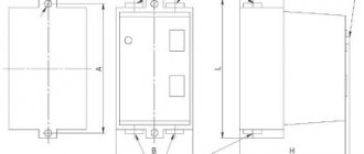
Version: stationary (mounting on a circuit board).
Table 13.1. EH series motor contactors
| Type | Engine power, kW | Rated operating current, A | Number of cycles (millions) |
| EH 145 | 75 | 145 | 10 |
| EH 175 | 90 | 185 | 10 |
| EH 210 | 110 | 210 | 10 |
| EH 260 | 140 | 260 | 10 |
| EH 300 | 160 | 305 | 10 |
| EH 370 | 200 | 400 | 5 |
| EH 550 | 280 | 550 | 5 |
| EH 700 | 370 | 700 | 5 |
| EH 800 | 400 | 720 | 5 |
Rice. 11. EH series motor contactors
Table 13.2. Overload thermal relays
| Thermal relay | Contactors | Current setting range, A |
| T 200 DU | EH 145 EH 175 EH 210 | 80¸200 |
| T 450 DU | EH 175 EH 210 EH 260 EH 300 EH 370 | 130¸400 |
| T 900 DU | EH 370 EH 550 EH 700 EH 800 | 265¸850 |
Table 13.3. Time relay blocks (pneumatic)
| Contactor | Relay | Delay range |
| EH 175¸EH 800 | TP 40 D TP 180 D | with pneumatic attraction delay (blue handle) · 0.1¸40 s · 10¸180 s |
| TP 40 I TP 40 I | with pneumatic drop-off delay (black handle) · 0.1¸40 s · 10¸180 s |
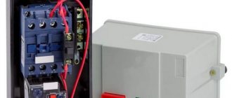
Device and principle of operation
Today, manufacturers have launched the production of magnetic starters, which are used in all areas of industry, transport, and everyday human activity. They differ in design, complexity of the control circuit, overall dimensions, magnitude of current loads, degree of protection from the influence of the external environment, but they are all united by the fact that their operation is based on one principle.
Figure 1 Design of a magnetic starter of the PM12 series
The plastic housing of the magnetic starter consists of two parts (2) and (3). In the lower part (3) there is the main working element - the magnetic system of the starting device, consisting of a retractor coil (6), an armature (4) and a core (7), assembled from W-shaped plates made of electrical steel.
A retractor coil (6) and a return spring (11) are placed on the middle core of the fixed core (7), which is attached to the body (3) with a plate (8). In order to soften the dynamic load, a shock absorber (8) is installed between it and the iron of the core.
The body has special guide grooves along which the traverse (1) makes reciprocating movements. The movable part of the magnetic system (armature) and the starter contact bridge (12) are rigidly attached to the traverse
A short-circuited coil (5) is attached to the outer cores of the core in special grooves, ensuring gentle operation of the coil.
When current passes through the turns of the coil, a field is created, under the influence of which the moving part of the magnetic system of the actuator is drawn into it. The movement of the armature towards the coil carries along the traverse along with the device for closing and opening the power and auxiliary contacts of the starter. When the PM is de-energized, the return spring returns the armature to its original position, which will cause the contacts to open.
At the base of the housing there is a clamp designed for quick-release fastening of the starter to the DIN rail.
Installation Tips and Tricks
- Before assembling the circuit, you need to free the working area from the current and check that there is no voltage with a tester.
- Set the core voltage designation which is mentioned on it and not on the starter. It can be 220 or 380 volts. If it is 220 V, phase and zero go to the coil. Voltage marked 380 means different phases. This is an important aspect, because if connected incorrectly, the core may burn out or will not fully start the necessary contactors.
- Starter button (red) You need to take one red “Stop” button with closed contacts and one black or green button with the inscription “Start” with invariably open contacts.
- Please note that power contactors only force or stop the phases, and the zeros that come and go, conductors with grounding are always combined at the terminal block, bypassing the starter. To connect a 220 Volt core to the addition, 0 is taken from the terminal block into the design of the starter organization.
You will also need a useful device - an electrician's tester, which you can easily make yourself.
{SOURCE}
220 volt coil: connection diagrams
To control the operation of the magnetic starter, only two buttons are used - the “Start” button and the “Stop” button. Their design can be different: in a single housing or in separate housings.
Buttons can be in the same housing or in different ones
Buttons produced in separate housings have only 2 contacts, and buttons produced in one housing have 2 pairs of contacts. In addition to the contacts, there may be a terminal for connecting the ground, although modern buttons are produced in protected cases that do not conduct electric current. Push-button stations in a metal case for industrial needs are also produced, which are highly impact resistant. As a rule, they are grounded.
Connection to 220 V network
Connecting a magnetic starter to a 220 V network is the simplest, so it makes sense to start familiarizing yourself with these circuits, of which there may be several.
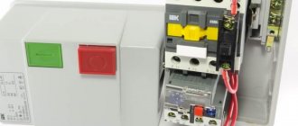
A voltage of 220 V is supplied directly to the coil of the magnetic starter, which are designated as A1 and A2, which are located in the upper part of the housing, as can be seen from the photo.
Connecting a contactor with a 220 V coil
When a regular 220 V plug with a wire is connected to these contacts, the device will start working after the plug is plugged into a 220 V socket.
Using power contacts, it is permissible to turn on/off an electrical circuit for any voltage, as long as it does not exceed the permissible parameters indicated in the product passport. For example, you can apply battery voltage (12 V) to the contacts, with which a load with an operating voltage of 12 V will be controlled.
It should be noted that it does not matter which contacts the single-phase control voltage is supplied to, in the form of “zero” and “phase”. In this case, the wires from contacts A1 and A2 can be swapped, which will not affect the operation of the entire device.
It is quite natural that such a switching circuit is used extremely rarely, since it requires direct voltage supply to the coil of the magnetic starter. In this case, there are many options for switching on, using a time relay or a twilight sensor, connecting, for example, street lighting to power contacts. The main thing is that the “phase” and “zero” are nearby.
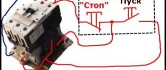
Using the Start and Stop buttons
Basically, magnetic starters are involved in the operation of electric motors. Without the presence of the “Start” and “Stop” buttons, such work is associated with a number of difficulties. This is primarily due to the operating characteristics of electric motors, which are often located at a considerable distance. The buttons are connected to the coil circuit in series, as in the figure below.
Switching diagram of a magnetic starter with buttons
This method is characterized by the fact that the magnetic starter will be in working condition as long as the “Start” button is pressed, which is very inconvenient. In this regard, the circuit includes additional (BC) contacts of the magnetic starter, which duplicate the operation of the “Start” button. When the magnetic starter is turned on, they close, so after releasing the “Start” button, the circuit remains operational. They are designated in the diagram as NO (13) and NO (14).
Connection diagram for a magnetic starter with a 220 V coil and a self-retaining circuit
You can turn off running equipment only using the “Stop” button, which breaks the electrical power supply circuit of the magnetic starter and the entire circuit. If the circuit provides other protection, for example, thermal, then if it is triggered, the circuit will also be inoperable.
Power for the motor is taken from the T contacts, and power is supplied to the magnetic starter contacts, designated L.
This video explains in detail and shows in what order all the wires are connected. In this example, a button (button post) is used, made in one housing. As a load, you can connect a measuring device, an ordinary incandescent lamp, a household appliance, etc., operating from a 220 V network.
How to connect a magnetic starter. Connection diagram.
Watch this video on YouTube
EMF design features
The design of an electromagnetic starter (EMF) is not highly complex. But this factor does not in any way reduce the reliability of the device.
How does this device work?
The reliability criterion is, for the most part, established by the correct connection of the circuits and the precise selection of the load.
If these criteria are met, the device will operate flawlessly for a long time in most cases.
The classic design of electromagnetic devices - starters, which are widely used in the field of power supply. There are many options for such devices, differing in shape and size.
The classic version includes the following elements:
- The body is dismountable in two halves.
- Inductor.
- Magnetic core.
- Switching mobile chassis.
- Group of main contacts.
- Group of auxiliary contacts.
The element of the magnetic starter, responsible for organizing the switching of the power circuit, is a movable chassis combined with one part (moving) of the magnetic circuit.
The chassis itself is made of dielectric material, and metal (brass) plates are used as closing contacts. At the ends of the plates there are contact patches made of refractory metals, usually a silver alloy.
A disassembled electrical switching device with a full set of parts included in the design. This is a simple classic device, while more advanced modern devices have a somewhat more complicated design.
The fixed part of the magnetic circuit is rigidly mounted inside the second half of the electromagnetic starter housing. An inductance coil is placed on this part of the magnetic circuit and a return spring is installed.
The second part of the device body is also equipped with contacts for power and auxiliary groups. These contacts are rigidly fixed to the housing using screws.
This is what the contact power group of one of the starter designs looks like in a classic design. Meanwhile, the design of the devices is characterized by a variety of configurations, which does not allow specific reference to individual parts.
The design of a standard magnetic starter involves combining two halves of the housing, as a result of which the two halves of the W-shaped magnetic circuit are also combined into a single structure.
At the same time, due to the return spring, a small gap remains between the halves of the magnetic circuit; the main contact groups in this position remain broken.
Operating principle of EMF
The operating principle of the device is based on the effect of electromagnetic induction. If there is no voltage on the coil located inside the starter, the magnetic circuit remains in the “with gap” position, the main contacts are broken.
The inductor of a classical device, the force of the magnetic field of which attracts the contact moving chassis. And an ordinary metal spring, due to which the movable chassis is pressed out
When an electric current is passed through the coil, under the influence of a magnetic field, the second (moving) part of the magnetic circuit overcomes the force of the spring and is attracted to the first (fixed) part.
Accordingly, the main contact groups of the starter are closed by the plates of the movable chassis.
The reverse process is obvious - when the voltage is removed from the terminals of the inductor, the magnetic field ceases to operate, and under the force of the return spring, the movable chassis and the second part of the magnetic circuit are repelled. Accordingly, the magnetic starter returns to the contact-break state.
The second is the upper moving part of the assembly, thanks to which the switching principle is carried out. On the right, individual contacts of the power group are also shown, dismantled from the seats of the insulated housing
It should be noted that based on the configuration of the electrical device, the circuit of contact groups can have a very different structure. Especially regarding auxiliary contacts, which may be in a closed or open state in contrast to the state of the main contacts of the device.
A feature of modern designs of magnetic starters is the modernization of the inductor control circuit.
If the design of previous “outdated” devices involved direct supply of voltage to a coil taken from one of the phases, electronic circuits are now increasingly used.
The design of an electrical line switch, where an additional electronic board is used in the inductor power supply circuit. After processing by the board, the coil receives a DC supply voltage
For example, known products are equipped with an electronic circuit for stabilizing the voltage supplied to the terminal of the inductor coil of the magnetic starter.
Controlling the coil through an electronic circuit is characterized by the fact that the alternating voltage is first rectified and then a pulse signal is generated. This approach provides increased service life and improved stability of operation.
Design and principle of operation
Power for the motor or any other load phase from B is supplied to any of the contacts marked with the letter L, and is removed from the contact located underneath it marked T. Below we will look at some diagrams for connecting a magnetic starter for volts and volts, which may be useful at home.
This connection allows switching with buttons from any position.
The connection diagram for a magnetic starter with self-retaining is as follows: Let's consider the operation of the circuits for turning on and off the magnetic contactor.
The power part has also been slightly changed From to
Please note that they use contacts with different purposes to control the starter.
We recommend: Luxar deco switch how to connect
Post navigation
Connection to a 3-phase network It is possible to connect 3-phase power through an MP coil operating from V. On the KM2 contactor, phases L1 are replaced by L3, and L3 by L1, thus changing the direction of rotation of the electric motor. Voltage with a designation means different phases. Connection diagram for a magnetic starter on B Connection to B is practically no different from the first option, the only difference is in the supply voltage of the magnetic coil.
The entire circuit will operate from two phases. The relay is connected to the output from the MP to the electric motor, electricity passes through it in a series manner through the heating of the relay to the electric motor. We also recommend reading our other article where we talked about how to select and connect an electromagnetic starter on V. Connecting a magnetic starter with a thermal relay A magnetic starter is, in fact, a powerful special-purpose relay. The second type is used to supply power; it is the most common.
In case of overload, the thermal sensor P will operate and break contact P, the machine will stop. A coil is installed in the slot in the lower part of the magnetic circuit. What does a practical wiring diagram for connecting a magnetic starter look like?
Next you need to install a jumper in the button post. The faster the opening occurs, the smaller the arc and the better condition the contacts themselves will be. The whole scheme as a whole undergoes minor changes. If there are special safety requirements and high humidity in the room, it is possible to use a starter with a 24-12 volt coil. Reversing magnetic starters in a single-phase network. Reversible electric motor connection diagram.
Connection Instructions
Connecting to a 3-phase network It is possible to connect 3-phase power through an MP coil operating from V. If the inscription reads V AC or there is an AC icon next to it, then a phase and a zero are required for the control circuit to operate. The latter is designed for quick disconnection of contacts, the speed of which determines the magnitude of the electric arc. This is an important aspect, because if connected incorrectly, the core may burn out or will not fully start the necessary contactors. A graphical representation of the control, which consists of a coil, buttons and additional contactors that take part in the operation of the coil or prevent erroneous activation. Now, having double-checked the correct installation, you can apply voltage and check the functionality of the circuit. This attachment snaps into special holders; its contact groups work together with the groups of the main body. After completing the above steps, the electric motor will be turned off and ready for subsequent start-up from the push-button station. Starter control buttons In general, you will need two buttons: one to turn on and one to turn off. The need for a specific push-button contact It is known that the contactor of a magnetic starter is turned on by a control pulse emanating from pressing the start button, which applies voltage to the control coil. MP connection diagrams differ mainly depending on which coil is located in it. Such buttons usually have two pairs of contact groups - one normally open, the other closed.
Search on the site
Reversible circuit for connecting an electric motor through starters In some cases, it is necessary to ensure that the motor rotates in both directions. Keeping the contactor in the on state occurs according to the principle of self-retaining - when an additional auxiliary contact bypasses and is connected in parallel with the start button, thereby supplying voltage to the coil, as a result of which there is no need to hold the start button pressed. With a cross connection scheme, simultaneous operation of both starters will result in a short circuit. The coil will activate the KM1 contacts and they will close the circuit with the motor windings. Voltage with a designation means different phases.
When the armature is completely lowered, the contacts thrown by the spring are disconnected. The power supply to the control coil after connecting the magnetic starter is supplied by alternating current, but for this device the type of current does not matter. A correctly connected starter should be locked in the on position when mechanically pressing on the moving part of the magnetic circuit. The type of voltage does not matter, the main thing is that the rating does not go beyond V. Now, if you release it, the magnetic starter continues to operate until the voltage disappears or the thermal relay P for motor protection is triggered. At the same time, the starter core attracts the armature, resulting in the closure of the moving power contacts, after which voltage is supplied to the load.
But there is only one correct one. This is the so-called push-button post. You can also make a single-line graphic drawing of the connection of a three-phase electric motor to a magnetic starter via a relay. Magnetic switch. Or how to connect a three-phase motor