The transistor is a very important element in most radio circuits. Those who decide to engage in radio modeling must first of all know how to test them and what devices to use.
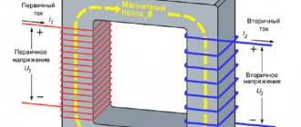
Before starting the test, first of all, the structure of the triode device is determined, which is indicated by the emitter junction arrow. When the direction of the arrow points towards the base, then this is the PNP variant, the direction opposite to the base indicates NPN conductivity.
Testing a PNP transistor with a multimeter consists of the following sequential operations:
- We check the reverse resistance ; to do this, we connect the “positive” probe of the device to its base.
- The emitter junction is tested , for this we connect the “negative” probe to the emitter.
- To check the collector, move the negative probe onto it.
The results of these measurements should show a resistance within the value of “1”.
To check direct resistance, swap the probes:
- “negative” probe of the device to the base.
- “positive” probe from the emitter to the collector.
- On the multimeter screen, the resistance readings should be from 500 to 1200 Ohms.
These readings indicate that the transitions are not broken, the transistor is technically sound.
Many amateurs have difficulty identifying the base, and, accordingly, the collector or emitter. Some advise starting to determine the base, regardless of the type of structure, in this way: alternately connecting the black probe of the multimeter to the first electrode, and the red probe alternately to the second and third.
The base will be detected when the voltage across the device begins to drop. This means that one of the transistor pairs has been found - “base-emitter” or “base-collector”. Next, you need to determine the location of the second pair in the same way. The common electrode of these pairs will be the base.
What kind of lighting do you prefer?
Built-in Chandelier
Expert opinion
It-Technology, Electrical power and electronics specialist
Ask questions to the “Specialist for modernization of energy generation systems”
Measuring the parameters of field-effect transistors Thus, by reducing or increasing the channel width, you can regulate the current strength between the source and drain or isolate them from each other. Ask, I'm in touch!
Instructions for checking with a tester
Testers differ by type of model:
- There are devices that are designed with devices that allow you to measure the gain of low-power microtransistors.
- Conventional testers allow testing in ohmmeter mode.
- The digital tester measures the transistor in diode test mode.
In any case, there is a standard instruction:
- Before starting the test , it is necessary to remove the charge from the shutter. This is done like this: literally for a few seconds the charge must be short-circuited with the source.
- In the case when a low-power field-effect transistor is being tested , then before picking it up, you must remove the static charge from your hands. This can be done by holding your hand on something metal that has a ground connection.
- When checking with a standard tester , you must first determine the resistance between drain and source. In both directions it should not make much difference. The resistance value with a working transistor will be small.
- The next step is to measure the junction resistance, first direct, then reverse. To do this, you need to connect the tester probes to the gate and drain, and then to the gate and source. If the resistance in both directions is different, the triode device is working properly.
They should be as short as possible and have a large cross-section. If this module is located close to another source of pulse signals (for example, next to the generator Figure 1), the generation of the node on the chip may be disrupted. Therefore, it is better to assemble the “ESR” measurement unit on a separate small board and place it in a screen (for example, made of tin) connected to a common wire.
To calibrate the “ESR” scale, connect resistors with a resistance of 0.1,0.2,0.5,1,2.3 Ohms to the “ESR” and “Common” terminals and make the corresponding marks on the scale. The sensitivity of the device can be adjusted by changing the resistance of the tuning resistor R5. The ESR meter is powered, just like the rest of the module circuits, with a voltage of 9 V.
Device module connection diagram
If desired, you can supplement the device with a module for quickly checking transistors. It can be used to test any bipolar transistors, as well as low- and medium-power field-effect transistors. Moreover, bipolar transistors and, in some cases, field-effect transistors can be checked without removing them from the circuit.
Figure 5. Replacing KT829G
Depending on the type of LEDs used, you may have to select resistance R5, focusing on the optimal brightness of their glow, or install an additional quenching resistor in the 9 V power circuit. It should be noted that this circuit works with a supply voltage starting from 2 V. When to terminals “E”, “B”,
“K” has nothing connected, both LEDs are blinking. The blinking frequency can be adjusted by changing the capacitance of capacitors C1 and C2. When a working transistor is connected to the terminals, one of the LEDs will go out, depending on its conductivity type - p-n-p or n-p-n. If the transistor is faulty, both LEDs will blink (internal open) or both will go out (short).
In addition to the terminals “E”, “B”, “K” on the device itself (terminal block, “fragment” of a socket for microcircuits, etc.), in parallel with them, you can remove the corresponding probes from the housing on the wires to test transistors on the boards. When testing field-effect transistors, terminals “E”, “B”, “K” correspond to terminals “I”, “3”, “C”.
Figure 6. Low voltage voltage stabilizer
It should be noted that it is still better to check field-effect transistors or very powerful bipolar transistors by removing them from the board. When measuring the values of any elements directly on the board, be sure to turn off the power to the circuit in which the measurements are being made!
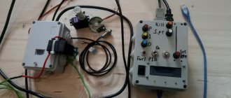
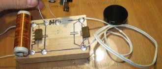
The device takes up little space, fitting into a 140x110x40 mm case (see photo on the right at the beginning of the article) and allows you to test almost all the main types of radio components most often used in practice with sufficient accuracy for radio amateurs. The device has been in use for several years without any complaints.
Expert opinion
It-Technology, Electrical power and electronics specialist
Ask questions to the “Specialist for modernization of energy generation systems”
Do-it-yourself tester - I want to know Schematic diagram of a generator-probe using a piezofilter The probe is designed for testing ultrasonic frequencies and tuning intermediate frequency paths, as well as other high-frequency or broadband aperiodic cascades of radio receivers. Ask, I'm in touch!
Checking a Composite Transistor
Such a semiconductor element is also called a “Darlington transistor”; in fact, it is two elements assembled in one package. For example, Figure 6 shows a fragment of the specification for KT827A, which displays the equivalent circuit of its device.
Figure 6. Equivalent circuit of the KT827A transistor
It will not be possible to check such an element with a multimeter; you will need to make a simple probe, its diagram is shown in Figure 7.
Rice. 7. Circuit for testing a composite transistor
Designation:
- T is the element being tested, in our case KT827A.
- L – light bulb.
- R is a resistor, its value is calculated using the formula h21E*U/I, that is, we multiply the input voltage by the minimum gain value (for KT827A - 750), divide the resulting result by the load current. Let's say we use a light bulb from the side lights of a car with a power of 5 W, the load current will be 0.42 A (5/12). Therefore, we will need a 21 kOhm resistor (750 * 12 / 0.42).
Testing is carried out as follows:
- We connect the plus from the source to the base, as a result the light bulb should light up.
- We apply minus - the light goes out.
This result indicates the functionality of the radio component; other results will require replacement.
What it is
A transistor tester is a universal digital measuring device that can test not only transistors, but also other elements. Both semiconductor elements - thyristors, triacs, diodes and others, as well as passive elements, for example: resistors, capacitors, inductors.
However, in most cases, it is more convenient and faster to check the above elements for serviceability with a multimeter, but this device is still useful as an ESR tester.
ESR is equivalent series resistance, an important parameter for electrolytic capacitors. Due to the impossibility of measuring it with a household multimeter, and specialized ESR meters are expensive, it is much more difficult for beginners to diagnose faults in electronic circuits.
With the help of transistor testers, you can measure ESR with normal accuracy, and the cost of these devices is in the range of 10-20 dollars, depending on the model.
Expert opinion
It-Technology, Electrical power and electronics specialist
Ask questions to the “Specialist for modernization of energy generation systems”
A device for testing transistors without desoldering from the circuit. Both semiconductor thyristors, triacs, diodes and others, as well as passive elements, such as resistors, capacitors, inductors. Ask, I'm in touch!
Preparing tools
Every modern radio amateur has a universal tool called a digital multimeter. It allows you to measure direct and alternating currents and voltages, resistance of elements. It also allows you to check the functionality of circuit elements. Next to the switch for the “dialing” mode, as a rule, there is a diode and a speaker (see photo in Fig. 1).
Figure 1 – Multimeter front panel
Before checking the element, you need to make sure that the multimeter itself is working:
- The battery must be charged.
- When switching to semiconductor test mode, the display should show the number 1.
- The probes must be in good working order, since most devices are Chinese, and breaking the wire in them is a very common occurrence. You need to check them by leaning the tips of the probes against each other: in this case, zeros will appear on the display and a squeak will be heard - the device and probes are working.
- The probes are connected according to the color marking: the red probe goes into the red connector, the black probe goes into the black connector labeled COM.
If you do not know how to use this device, we recommend reading the detailed instructions for dummies on how to use a multimeter!
Device Features
According to their design features, all transistors are:
- Bipolar (BT);
- Field or unipolar (PT);
- Composite (CT).
Before you start checking the integrity of a part with a digital multimeter, it is important to understand what a BT is. This is a three-layer semiconductor
Roughly speaking, these are 2 diodes connected to each other. Depicting it this way, it will be easier to understand the scheme for checking it on the board itself without desoldering.
In terms of conductivity, bipolar semiconductors are of two types:
- npn;
- pnp;
They are also most easily represented as diodes, photographs of which are often posted to explain the importance of understanding the structure and how it works. The output current occurs with the participation of holes and electrons - two carriers of different polarities, allowing them to be controlled.
The contacts involved in a semiconductor are called:
- base;
- emitter;
- collector.
The middle layer is connected to the base. To the emitter and collector - the extreme ones. The direction of the current is marked with an arrow. It is located near the emitter.
In a DC, the electric field is directed perpendicular to the current current. Their contacts are called as follows:
- gate;
- drain;
- source.
Also in their design there is an additional (conductive layer) for the flow of electric current through it.
PTs come in various modifications. With “p” or “p” channels, horizontal and vertical arrangement, near-surface and volumetric configuration.
Everything ingenious is simple!
I set out to make something simpler and more reliable. I liked the idea with a current source; by carrying out measurements on a fixed (previously known) emitter current, we can reduce the required number of measuring instruments (ammeters). Then I remembered my favorite microcircuit TL431 . The current generator on it is built from only 4 parts: Considering the not very large load capacity of this microcircuit (and it is extremely inconvenient to mount it on a radiator), to test powerful transistors at high currents we will use Mr. Darlington : Now there’s a catch - it’s not in any reference book current source circuits based on TL431 and transistor “pnp” structure. Siklai , no less respected by me, helped solve this problem :
Yes, an inquisitive eye will notice that the currents of both transistors flow through the current-setting resistor here, which introduces some error in the measurements. But, firstly, with values of the base current transfer coefficient of transistor T2 above 20, the error will be less than 5% , which is quite acceptable for amateur radio purposes (we are not launching the Shuttle to Venus).
Secondly, if we do launch the Shuttle and we need high accuracy, this error can easily be taken into account in the calculations. The emitter current of transistor T1 is almost equal to the base current of transistor T2, and this is what we will measure. As a result, when calculating h21e (and this is very convenient to do in Excel), instead of the formula: h21e=Ie/Ib, you need to use the formula: h21e=Ie/Ib-1
To minimize this error, as well as to ensure normal operation of the TL431 microcircuit in a wide range of currents, a transistor with maximum h21e should be selected as transistor T1. Since this is a low-power bipolar transistor, until our device is ready, you can use a Chinese multimeter. I managed to find an instance with a value of 250 out of only 5 KT3102 transistors.
Since today in the household of any radio amateur there is a Chinese multimeter (or even more than one), we will use it as a base current meter, which will allow us not to fence switching for different ranges of base currents (I have a multimeter with automatic limit selection measurements), and at the same time exclude the rectifier bridge from the circuit - the digital multimeter does not care about the direction of the flowing current.
If your feet smell bad, remember where they come from.
After googling a little, I found a diagram of a device for testing transistors, which was replicated on a fairly decent number of sites. Simple, portable... but no one except the author himself praises it. This should have been confusing right away, but alas.
So, the original circuit (with slightly simplified indication and switching):
Click to enlarge
According to the author's idea, here the operational amplifier together with the transistor under test forms a source of stable current. The emitter current in this circuit is constant and is determined by the value of the emitter resistor. Knowing this current, all we have to do is measure the base current, and then by dividing one by the other, obtain the value h21e. (in the author’s version, the scale of the measuring head was immediately calibrated in h21e values).
Two bipolar transistors at the op-amp output serve to increase the load capacity of the microcircuit when measuring high currents. The diode bridge is included in order to eliminate the need to reconnect the ammeter when switching from “pnp” to “npn” transistors. To increase the accuracy of selecting complementary pairs of bipolar transistors, it is necessary to select zener diodes (setting the reference voltage) with the stabilization voltages as close as possible.
I was immediately confused by the “not entirely correct” switching on of the operational amplifier with a single-supply supply. But the breadboard will endure everything, so the circuit was assembled and tested.
Shortcomings immediately emerged. The current through the transistor was highly dependent on the supply voltage, which never resembles a stable current generator. What the author of the circuit managed to select, while powering the device from a battery, remains a big mystery. As the battery discharges, the “exemplary” current will flow away and quite noticeably. Then I had to tinker with the “amplifier” at the op-amp output, otherwise the circuit would work unstably when measuring transistors of different powers. It was necessary to select the value of the resistor, and then I switched to a more “classical” version of the amplifier. And the bipolar (correct) power supply of the op-amp solved the problem with the floating current.
As a result, the diagram took the form:
Click to enlarge
But here another drawback has emerged - if you confuse the conductivity of the bipolar transistor (turn on “pnp” on the device, and connect the “npn” transistor), and when selecting from a large number of transistors, you will definitely forget to switch the device sooner or later, then one will fail from the transistors of the “amplifier” and you will have to repair the device. And why do we need difficulties with bipolar power supply, opamp, amplifier, etc.?
Construction and details.
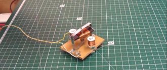
Due to the simplicity of the device, no printed circuit board was developed; all elements are soldered to the pins of switches and connectors. The entire structure can be assembled in a small case; everything will depend on the dimensions of the transformer and switches used.
When testing powerful bipolar transistors at high currents (100mA and 500mA), they must be mounted on a radiator! If a plate radiator is mounted on one of the walls of the device or the radiator itself is used as a wall of the device, this will make using the device more convenient. A radiator that is always with you! This will significantly speed up the process of testing powerful transistors in TO220, TO126, TOP3, TO247 and similar packages.
The power supply stabilizer chip also needs to be installed on a small radiator. Any diode bridge is suitable for a current of 1A and higher. As a transformer, you can use a suitable small-sized one, with a power of 10 W or more with a secondary winding voltage of 10-14 V.
Optional: the device for testing transistors has sockets for connecting a second multimeter (included in the DC voltage measurement mode to a limit of 2-3V). I spotted this idea on one of the forums. This allows you to measure Ube of the transistor (if necessary, calculate the slope). This function is very convenient when selecting bipolar transistors of the same structure for PARALLEL connection in one arm of the amplifier output stage. If at the same current the voltages Ueb differ by no more than 60 mV, then such transistors can be connected in parallel WITHOUT emitter current equalizing resistors. Now do you understand why Accuphase amplifiers, where up to 16 transistors are connected in parallel in each arm in the output stage, cost so much money?
List of elements used:
Resistors: R3 - 820 Ohm, 0.25 W, R4 - 1k2, 0.25 W, R5 - 510 Ohm, 0.25 W, R6 - 260 Ohm, 0.25 W R7 - 5.1 Ohm, 5 W (more is better), R8 - 26 Ohm, 1 W, R9 - 51 Ohm, 0.5 W, R10 - 1k8, 0.25 W.
Capacitors:
C1 - 100nF, 63V, C2 - 1000uF, 35V, C3 - 470uF, 25V
Switching:
S1 - switch type P2K or biscuit for three positions with two groups of contacts for switching, S2 - switch type P2K, toggle switch or biscuit with one group of contacts for switching, S3 - switch type P2K or biscuit for two positions with four groups of contacts for switching, S4 - momentary button, S5 - power switch
Active elements:
T3 - transistor type KT3102 or any low-power npn type with high gain, D3 - TL431, VR1 - integrated stabilizer 7812 (KR142EN8B), LED1 - green LED, BR1 - diode bridge for a current of 1A.
Miscellaneous:
Tr1 is a transformer with a power of 10W or more, with a secondary winding voltage of 10-14V, F1 is a 100mA...250mA fuse, terminals (suitable available) for connecting measuring instruments and the transistor under test.