Currently, the air entry into a country house from the main section of the power line is almost always carried out with an insulated SIP wire.
The cable is used only for underground installation. Installation of SIP underground, even in a protective pipe, is prohibited.
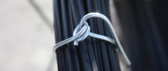
In the old days, with air input, you only had to buy the cable itself or insulated wires of the required length, an electrician would come with pliers and connect it all to a comb or gander within half an hour.
Installation of SIP, with all its advantages, is associated with certain difficulties and its own technological features.
You most likely won’t connect it yourself, but it’s still worth knowing the main points that need to be checked when working as an electrician.
SIP installation rules
With the growing number of energy consumers, SIP wires are effectively replacing conventional bare wires due to their practicality, reliability and safety. Self-supporting wire is widely used in the construction of new power lines, and SIP of four different modifications is also very popular in everyday life. Laying an electrical network using a self-supporting wire allows you to reduce the time it takes to put electrical networks into operation and provide electricity to residential and industrial facilities as quickly as possible. But to carry out installation work yourself, you need to know how to fasten SIPs. Methods for attaching SIP to a pole, types of fasteners, types of self-supporting cables, installation rules, recommendations from specialists when working with SIP will be discussed below.
Connecting the branch to the house with cables on a supporting cable
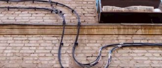
The steps for connecting the cable on the supporting cable are the same as for connecting SIP wires. Only between the house and the support is the supporting steel cable stretched. To attach the cable to the wall of the house and to the pole, anchors with loops for cables or tension couplings are used, which are attached to the anchors with coupling connecting strips (see photo).
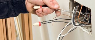
The wires themselves are connected to the wires of the main line using special die clamps to bare wires or piercing clamps to insulated wires. And the cables are secured to the cable with cable banding straps.
I will dwell in more detail on attaching anchors to the wall of the house and to the pole.
Description and types of SIP
A self-supporting electrical wire consists of several wires isolated from each other (aluminum wire intertwined). When laying new lines in accordance with GOST R 52373-2005, it is necessary to use a self-supporting cable. According to the new PUE rules, these cables are recommended to be used to connect electricity consumers.
Today there are the following types of SIP:
- SIP-1. This is a four-core cable used in three-phase electrical networks with voltages up to 1000 V. Moreover, three of its cores are designed for connecting phases (isolated from each other), and the fourth (zero) is without braid and has a steel core. They also produce SIP-1A cable, in which the neutral core is insulated.
- SIP-2. All cores in this cable are insulated. Its scope of application is the same as that of the cable described above.
- SIP-3. This is a single-core wire with polyethylene insulation. Thanks to the steel core, it is highly durable. It is used in electrical networks up to 35 kV.
- SIP-4. This is a four-core cable with polyethylene insulation, designed for power lines up to 1000 V. It does not have a steel core. It is often used to make branches from the main power line in country houses and in the private sector.
- SIP-5. It includes two or more insulated conductors, all of them without a steel core. This cable is used in electrical networks up to 1000 V.
What kind of SIP is needed to connect a house?
Which SIP wire should I use? The best option is SIP-4 (4*16) with three-phase input 380V or SIP-4 (2*16) with single-phase 220V.
How SIP-1,2,3,4,5 differ from each other, read in a separate article.
Mistake #2
No suspension cables are required here.
It’s not for nothing that the wire is called self-supporting.
Advantages and disadvantages of using SIP
These wires allow:
- ensure the required electrical safety class;
- increase network reliability during operation;
- reduce the cost of maintaining the electrical network (up to 80%);
- reduce installation time and reduce labor costs;
- place electrical lines on the walls of buildings;
- reduce losses during electricity transmission (due to low resistance);
- connect objects without disconnecting the main supply line;
- lay and connect lines on your own.
- cost 20-25% more than conventional wires without insulation;
- many energy suppliers are not ready to use SIP (outdated equipment and no tools for installation);
- Only overhead power lines can be laid.
Let's build your dream home together
If you find yourself here, then you have a task: to introduce electricity into your private home. And of course there are many questions in my head: which cable to choose? Which introductory machine should I install? Which counter should I choose? And in the end, how to combine all this into one properly working system. We would like to share our experience of how we carried out air entry into our country house.
It was necessary to replace all this old stuff with something modern, and the best option to do this was using 2x16 SIP wires.
Types of fasteners for SIP
To lay a self-supporting wire, use the following fasteners:
- intermediate support clamps;
- brackets for fastening anchor clamps;
- brackets for fastening intermediate clamps;
- anchor brackets for power consumer wires;
- anchor clamps for insulated load-bearing neutral core;
- anchor clamps for power consumer wires;
- mounting hooks;
- fastening tape (the tape must be made of stainless steel);
- stainless steel clamps;
- stainless steel yokes;
- fastening ties;
- facade fastenings for SIP;
- Spiral knits.
Many clamps allow you to attach two self-supporting cables at once. To do this you need to use another clamp. In this case, fastening the SIP will save not only materials, but also free space. Do not use simple cable ties for this purpose. You only need to install clamps for the self-supporting wire - they are wide. In addition, they are made of high-strength plastic, so they are more durable.
Anchor clamps
Using these clamps, SIPs with an insulated load-bearing neutral core are secured. The anchor clamp consists of a body and self-adjusting wedges that allow you to carefully clamp the neutral core.
Thanks to the flexible cable, you can install up to three clamps on one bracket.
Facade and pillar brackets
The brackets securely hold the anchor clamps on the facade. They differ in design. When choosing these fasteners, you need to consider the purpose for which the cable is used, because power wires often get very hot (heating of the cores up to 90°C is allowed). Such fittings for fastening SIPs must provide a large gap between the walls and the cable so that it is well cooled.
For installation with tape, use brackets with large limiting projections. During the operation of power lines, a backlash appears in them, which is associated with the stretching of the tape. If these SIP fastening units are on supports with small protrusions, then it can jump off the fastening point.
Purpose
The main purpose of branch clamps is to ensure uninterrupted delivery of electricity to specific consumers. If the main power network is connected directly to an energy source, then the supply cables are first connected to the power lines.
The purpose of the clamps is to guarantee a safe and reliable connection, as well as the movement of current along the supply towards the connected object.
For SIP wires, safe clamps with additional housing insulation are used. They allow you to quickly install bends without the need to remove insulation.
Thanks to this, the method of branching the electrical network using clamps is much more popular than the safety-violating method of twisting.
Tools and accessories for working with SIP
The following allow you to install a self-supporting wire efficiently and safely:
- tools for tensioning steel mounting tape;
- cable cutting scissors;
- scissors for cutting steel tape;
- winches;
- mounting stockings;
- mounting clamp;
- mounting rollers;
- swivels;
- hydraulic presses for crimping insulated sleeves and tips with cord brush;
- dynamometers;
- cord brushes;
- tools for installing reinforced ties;
- insulated spanners;
- grounding kits;
- separating wedges;
- short-circuit devices;
- universal claws and manholes;
- safety belts;
- slings;
- device for twisting wires.
Selection and calculation of input cable
The aluminum cable AVVG 2x10 mm2 was mentioned above, perhaps you were wondering where the figure came from? Everything is very simple, before purchasing we made a preliminary calculation of this conductor.
The cross-section of the cable for entry into the house is calculated based on the maximum permissible current at which heating of the conductor will not cause damage to the insulation of the input cable.
Those. our cable must withstand the current for a long time at which the thermal release of the machine will operate.
The thermal release current is assumed to be 15-20% greater than the rated current of the machine and is calculated using the formula:
Calculation of thermal release current
Now from the PUE, in tables 1.3.4 for copper conductors and 1.3.5 for aluminum conductors, we select the required cross-section of the cable laid in one pipe from the “ one two-core ” column, equal to or the nearest larger.
Table 1.3.4. Permissible continuous current for wires and cords with rubber and polyvinyl chloride insulation with copper conductors
| Conductor cross-section, mm 2 | Current, A, for wires laid | |||||
| open | in one pipe | |||||
| two single-core | three single-core | four single-core | one two-wire | one three-wire | ||
| 0,5 | 11 | — | — | — | — | — |
| 0.75 | 15 | — | — | — | — | — |
| 1 | 17 | 16 | 15 | 14 | 15 | 14 |
| 1,2 | 20 | 18 | 16 | 15 | 16 | 14,5 |
| 1,5 | 23 | 19 | 17 | 16 | 18 | 15 |
| 2 | 26 | 24 | 22 | 20 | 23 | 19 |
| 2,5 | 30 | 27 | 25 | 25 | 25 | 21 |
| 3 | 34 | 32 | 28 | 26 | 28 | 24 |
| 4 | 41 | 38 | 35 | 30 | 32 | 27 |
| 5 | 46 | 42 | 39 | 34 | 37 | 31 |
| 6 | 50 | 46 | 42 | 40 | 40 | 34 |
| 8 | 62 | 54 | 51 | 46 | 48 | 43 |
| 10 | 80 | 70 | 60 | 50 | 55 | 50 |
| 16 | 100 | 85 | 80 | 75 | 80 | 70 |
| 25 | 140 | 115 | 100 | 90 | 100 | 85 |
Table 1.3.5. Permissible continuous current for rubber and polyvinyl chloride insulated wires with aluminum conductors
| Conductor cross-section, mm 2 | Current, A, for wires laid | |||||
| open | in one pipe | |||||
| two single-core | three single-core | Four single-core | one two-wire | one three-wire | ||
| 2 | 21 | 19 | 18 | 15 | 17 | 14 |
| 2,5 | 24 | 20 | 19 | 19 | 19 | 16 |
| 3 | 27 | 24 | 22 | 21 | 22 | 18 |
| 4 | 32 | 28 | 28 | 23 | 25 | 21 |
| 5 | 36 | 32 | 30 | 27 | 28 | 24 |
| 6 | 39 | 36 | 32 | 30 | 31 | 26 |
| 8 | 46 | 43 | 40 | 37 | 38 | 32 |
| 10 | 60 | 50 | 47 | 39 | 42 | 38 |
| 16 | 75 | 60 | 60 | 55 | 60 | 55 |
| 25 | 105 | 85 | 80 | 70 | 75 | 65 |
According to the tables, cable cross-sections are suitable for us: 6 mm2 for a copper conductor and 10 mm2 for an aluminum conductor.
SIP installation instructions
This self-supporting wire is installed in stages.
The first stage is preparatory work.
At this stage you need:
- cut down and uproot trees and bushes under power lines, as well as around the installation site of tension and control devices. If these requirements are not met, the SIP insulation may be damaged during rolling;
- prepare the necessary tools and equipment.
The second stage is the dismantling of old poles and installation of new ones.
At the second stage, the old pillars are removed and new ones are installed. At the same time, before installing new supports, fasteners must be secured to them, because after installation, installing reinforcement on the support for fastening SIPs is problematic and more labor-intensive.
Reinforced concrete, wooden and iron supports are often installed under SIP. In this case, in places where the line turns, it is necessary to use double SIP anchors at an angle of 90°.
During installation, it is recommended to use double SIP anchors at turning points to securely fix the cable and protect it from damage.
The third stage is rolling out, fastening, tensioning SIP and connecting the energy consumer.
Self-supporting wire is supplied from manufacturers in spools. It can be rolled out manually with conductor sections up to 5 cm² and line lengths up to 100 m. In populated areas, you can manually roll out SIPs if the supports are located at a distance of up to 50 m from each other. In this case, you must comply with the basic safety requirements given below.
Sections and grades of sip are indicated in this table.
During rolling, the following rules must be observed:
- Be sure to use rollers in the work, because they protect the insulation from damage. It is impossible to roll out SIP on the ground due to the likelihood of damage to the polyethylene insulation and contamination of the cable with the ground. When installing a piercing clamp on contaminated soil, additional resistance appears, which leads to loss of electricity and overheating.
- Installing swivels is also a mandatory requirement, because it protects the multi-core cable from the cores unwinding, which leads to the appearance of gaps between them. These places can cause the wire to break due to external loads (strong wind or falling branches).
- The use of a connecting stocking allows you to maintain the integrity of the insulation and reliably connect the rope to the cable.
- When unrolling manually, the unwinding speed should not exceed 5 km/h so that the cable does not touch the ground, buildings and supports.
The rolling process is as follows:
- Place the reel on a stand or unrolling trolley.
- Place the stand behind the first pole of the power line being created (at a distance not less than the height of the support).
- Attach the mounting roller to the pole.
- Auxiliary rollers are attached to the remaining supports. They have different designs and markings because they are used on straight sections and on turns.
- Next, an auxiliary rope is passed from the end of the power line being installed to the beginning. For these purposes, use a rope of 6 mm or more.
- Then a rope is attached to the beginning of the cable. In this case, a mounting stocking and a swivel are used for connection to properly unwind the wire from the spool.
- Next, pull the rope and stretch the wire (placed on rollers) along all the posts. At the same time, slowly rotate the reel and pull the rope evenly. For this purpose it is allowed to use winches.
- Then they stretch and fasten the SIP in the anchors.
- Then remove the rollers and put clamps in their place.
- Next, the necessary branches from the power lines are made.
- At the final stage, the cable is installed and connected to the electric meter.
Installation of SIP on walls and siding
SIP insulation can be flammable, so attaching it to siding in the usual way is prohibited. To do this, you can use a metal sleeve (in which the cable is placed) and facade fasteners. To make a metal sleeve look aesthetically pleasing, you need to use a sleeve with double insulation.
But this option has pros and cons.
Advantages of facade fastening for SIP:
- The line looks the most attractive.
- Allows you to create increased protection.
- Costs for purchasing an iron hose and its fastening.
- It is impossible to create the necessary tightness of the structure.
- When laying the cable in a pipe, its cooling deteriorates.
- In hot weather, with an acceptable load, a self-supporting cable is not capable of passing the maximum permissible current. Therefore, insulation is often broken.
It must be remembered that ordinary self-supporting wire must not be laid inside the connected object. For these purposes, a non-flammable self-supporting cable marked Ng is provided.
Selection of fittings
The first step is to decide on the material. As mentioned above, one cable is no longer enough.
You will have to purchase a bunch of fittings, each of which has its own designation. Even electricians themselves are often confused about the nomenclature.
The air inlet consists of three main components:
- connection “node” on the support
- SIP
- connection “node” on the facade of the house
The summary table of fittings for purchase when connecting a three-phase 380V SIP input is as follows:
Mistake #1
Buy fittings designed specifically for the subscriber branch, and not for the main VLI.
Connection specifications usually specify universal clamps, brackets and tape. They can make both taps and mount the main VLI. You don't need this.
If the input is single-phase (220V), and not three-phase, then it will require another anchor for two wires and only 4 pieces of branch piercing clamps.
What you need to buy for single-phase SIP input:
Detailed labeling for each item, broken down by manufacturer, will be given below in separate plates.
Rules for laying cables along the facade of a building
The task itself looks somewhat strange. Why run wiring along the facade? First, let's understand the terms. If you go into the details of GOST: “a wire is a wire with or without a sheath...”, and “a cable is several wires...” and so on, you can get completely confused. Moreover, installing the wire along the wall of the building is impractical in principle. It must be inside. And if this is a power input, laying the cable along the facade of the building is generally prohibited; immediately after the suspension point it must be brought into the room.
All this is true, but we will talk about a relatively new cable (or wire, as defined by GOST) - SIP.
Self-supporting Insulated Wire (after all, a wire!) has recently been actively replacing non-insulated power wires. Residents of private houses know very well what it is. So, SIPs are allowed to be laid on the facades of buildings, and the norm is prescribed in the Rules for the Construction of Electrical Installations. When organizing the connection of households, this can bring significant savings for the owner.
Features of slider fastening systems
Slider fastening systems can be used for interior work or when decorating the facade of a building
But in addition to the fastening options presented above, there are others. The so-called slider mounts are attracting great interest. Although they are analogues of the described SF fasteners, slider fasteners still have a different design and have their own specific application.
From English “Sliding Systems” can be translated as “sliding systems”. The operation of slider mounts is based on the fact that partitions, windows or other transparent and opaque structures move freely along their guides. To do this, the latter must have special fittings. When using a slider system, you can get many advantages. It allows you to increase the amount of sunlight entering the room, save free space, and beautifully decorate the facade and interior.
The scope of application of slider systems is large. They can be used for interior work or when decorating the facade of a building. In the first case, doors, partitions or furniture elements are attached to the sliding system. The second one has mostly windows.
In what cases is it necessary to lay a power cable along the facade?
The most obvious option: if an obstacle in the form of a building appears in the path of an overhead power line. It can be bypassed by organizing a route loop in the power line. But it will cost extra design money, and extra wire, not to mention poles. This is how they used to do it (when power lines were built only on bare wires). And since the Rules for the Construction of Electrical Installations (PUE) allow the laying of SIP along the facade (or any other walls), it is possible to draw a power line directly through the obstacle.
But this applies to energy drinks. We are interested in the applicability of the PUE permit for private houses, in the area of responsibility of the owner of the property.
- If the switchboard in the house is located on one side, and the main power line is on the other, it was necessary to install another pole (the length of the overhead line is limited in length). Often right on the site. A self-supporting insulated wire is laid through the air to the nearest point of the building, and to the switchboard it can go along the wall.
- The mounting point from the pole is too high on the wall, and the shield is located at the surface of the ground. It is necessary to organize the so-called cable lowering. The SIP is attached to the wall before entering the panel.
As an alternative, a transition is made from the aluminum conductors of the self-supporting wire to the copper conductors of the input power.
And then the usual cable is laid along the facade.
Information: why make transitions from aluminum SIP to conventional VVG?
It would seem easier to tighten the input wire directly into the shield without buying crimp sleeves or piercing couplings. But connecting the SIP to the metering device (meter) is so problematic that it is easier to make the transition and lay the VVG cable along the wall of the building.
Inputting electricity into the house
As already noted, the connection of the input cable must be carried out by representatives of a specialized organization involved in power supply.
Currently, a residential building can be connected to power lines in three main ways:
- Laying an overhead line from a pole using bare aluminum wires. This method is considered the most dangerous and in practice its use has been significantly reduced.
- Input device from the overhead line with a self-supporting insulated wire (SIP cable). Reliable insulation allows you to avoid short circuits in any situation, and in the event of a cable break, there is no danger of electric shock to people.
- Entry into the house with a special armored cable laid underground. This method is considered the safest, especially for wooden houses, but also more expensive.
Since the main topic is SIP cable, it is worthwhile to dwell on its use as an input in more detail. This method is widely popular due to its design features and technical characteristics. However, when using this cable, certain conditions must be observed, especially when laying it along the wall of a wooden house.
Many experts are against the placement of SIP even in stone and brick houses. They consider the wire insulation to be insufficiently reliable in terms of physical strength characteristics. In this regard, SIP cables should not come into contact with any types of building structures. This reinsurance is explained by the protection of the overhead line from short circuit by an automatic circuit breaker, which is designed for a very high operating current. That is, the shutdown of the protective switch installed at the substation occurs with a certain delay. During this time, a powerful electric arc with a high temperature is quite capable of setting fire to the dry structures of a wooden house. However, there are many supporters of this method of laying, subject to certain safety measures.
One of these methods is to use a thick-walled metal pipe for insertion, which effectively localizes the action of the electric arc
Particular attention should be paid to the entrance and exit of the SIP cable from the pipe. To avoid possible chafing of the wire on the end of the pipe, it is provided with additional protection using a corrugated tube
One of the options for the input device could be a transition device from aluminum SIP conductors to a cable planned for laying inside a wooden building. It must be fire resistant and not spread fire. This part of the input, extended to the shield, is additionally protected by a circuit breaker. The machine is also used when bare wires are used connected to a piece of connecting cable. In all cases, the nominal value of the machine must be higher by one value compared to the input panel.
What does the Electrical Installation Rules say about this?
- The cable being laid should not experience tension or pressure loads.
- At transition points (couplings, piercing connections, etc.) insulation must be provided, the properties of which correspond to the characteristics of the main wire.
- All outlets and connections must be accessible for inspection and repair without mechanical intervention in the building structure.
- All connections of wire and cable cores are made in accordance with the PUE: crimping, welding, soldering or crimping.
- In the case when the cable is laid along the facade using pipes, flexible hoses, closed boxes, the possibility of quickly replacing the wiring is provided.
- Structural elements, insulation, transition points must be selected based on the environment of use: weather conditions, exposure to ultraviolet rays, temperature conditions.
- Metal parts of the structure must be protected against corrosion.
- The length of the cable laid along the wall of the building is calculated taking into account the temperature gaps for compression and tension. The movement of the wire under the influence of temperature should not create conditions for mechanical tensile forces.
- In places of connection, branching, transitions, slack is provided (cable reserve in case of reconnection or repair).
Selection and calculation of the introductory machine
To protect the input cable, we need to select a circuit breaker for input into the house, which is selected according to the rated current flowing through it when consumers are turned on. In order to determine the rated current of the input circuit breaker, it is necessary to calculate the total power of all consumers in the house. We have compiled a table showing the name and power of the consumer
| electrical appliance | Power, W |
| LCD TV | 200 |
| Fridge | 600 |
| Boiler | 2000 |
| Iron | 1500 |
| Electric kettle | 1800 |
| Microwave | 1000 |
| Computer | 500 |
| Lighting | 800 |
| Well pump | 1000 |
| Air conditioner | 400 |
| Total | 9800 |
But since consumers cannot all be turned on at the same time, the demand coefficient is used for calculations, which is equal to 0.7 when the number of receivers in the room is from 5 to 200.
Using the formula, we determine the estimated total active power of consumers:
Calculation of active power of all consumers
Next, you need to calculate the total total power of consumers in the house using the following formula:
Calculation of the total power of all consumers
Now we determine the calculated current for a single-phase network using the following formula
Rated current calculation
Now, based on the calculated current, we select the rating of the input circuit breaker. For internal power supply of apartments and houses, modular circuit breakers of standard ratings are used:
6, 10, 16, 25, 32, 40, 50, 63 A
The rated current of the machine must be equal to or the nearest greater from the standard range.
In our case, for an introductory machine, we need a machine with a rated current of 32 A
Laying cables along the facade of a building without making a transition
General rules for external installation on the wall of a building:
Minimum distances to elements for horizontal installation:
- above the frames of windows or doors - 30 cm;
- under window frames or balcony platforms (lower plane) - 50 cm;
- above the ground - 275 cm.
Minimum distances to elements for vertical installation:
- to window frames - 50 cm;
- to the edge of balconies or doors - 100 cm.
The minimum distance from the SIP to the wall is 6 cm.
The last point requires decoding. It refers exclusively to SIP, and is associated with the features of its design. This wire does not have an outer layer of insulation; only the current-carrying conductors are coated. The insulating material (PET) supports combustion and retains its properties only at temperatures up to 70–90°, depending on the modification. In addition, there is a SIP with a bare core, which is used as a zero wire.
Due to its low fire resistance, this cable should not be attached close to the wall. If the cable catches fire, the fire will not spread to the wall. For installation, special façade fastenings are used.
Important! If, after laying the cable, insulating panels will be mounted on the wall, the distance to the self-supporting insulation insulation is calculated according to the new outer plane, increasing by the thickness of the panels.
Attaching anchors to the wall of the house and to the pole
Depending on the cross-section, and therefore the weight, of the wires (cable) used for the branch, several options are used for attaching anchors to a wall or support.
Bolt hook. It is screwed into a special dowel, which is driven into a pre-made hole in the wall or support. The hook should be screwed into the main structure of the house, not into the sheathing. Suitable for light branch cables. For wooden structures, a hook with a screw tip is used.
Fastening anchors with through bolted connections to the wall. These are more reliable fastenings of anchors to the wall (see figure A and B).
Fastening anchors to the wall using an opening T-shaped fastening. A hole is drilled in the wall. When closed, the T-bar is a straight bar. After inserting into the hole, the mount opens and is held against the wall by the upper bar of the mount. (See Figure C)
Fastening anchors to the pole with crimping clamps. This is the most reliable way to attach anchors to a support post. The figure clearly shows the girth fastening technology. I will only add that instead of corners and studs, you can use a metal strip with a welded hook for the anchor. (In the figure “Installing anchors on column girths”)
We start dancing from the façade wall
First of all, you need to select a point on the wall from which the branch will begin. The rules for electrical installations do not regulate the choice of wall: it can be front or side. But in practice, in our latitudes it is the façade that is chosen. Roof slopes usually extend onto the side walls of buildings, from which ice (icicles) or snow can fall off.
The starting point for laying on the wall is considered to be the point where the cable exits the anchor clamp. The main design elements are shown in the illustration:
- Anchor bracket.
- An anchor clamp, after which the wire is not held on the overhead line route.
- Facade fastening is the first element of the wall installation system.
The bracket is installed at a height of at least 2.75 meters. The distance to the nearest corner of the load-bearing wall (excluding the thickness of the insulating material) is at least 10 cm.
Tip: If the cross-section of the power cable allows you to choose between different anchors, you should choose a hanger with a lower load. In this case, if there is a mechanical impact on the SIP (for example, caught by a truck on the road, or a pole falls), the wall will not be destroyed, the anchor will simply be torn off.
Methods and rules for laying HDPE pipes
- It is not recommended to lay cables of different networks in the cavity of one protective channel.
- Do not bend the pipe at an acute angle, as this may lead to the formation of a crease.
- The joints between the pipes must be sealed. Individual products can be connected using compression couplings, press fittings or butt welding.
- The length of the section between the boxes should not exceed 25 meters.
- When laying openly outside the building, black HDPE corrugation, resistant to ultraviolet radiation, should be used.
- To ensure the drainage of condensate formed on external surfaces, the pipelines must have a slope directed towards the duct boxes. Moisture will collect in them.
- When the channel is buried more than 2 meters into the soil, it is necessary to place a protective concrete screed 8–10 cm thick on top.
Laying pipes inside buildings
Installation of cable channels inside buildings is carried out in the following order:
- Cable routing markings.
- Punching grooves in the building envelope (if necessary).
- Connecting individual HDPE pipes into a pipeline and fixing them. To fasten products to walls or ceilings, special holders with a latch are used; to the floor, metal brackets are used.
- Sealing of the structure depending on the location of the channel and its diameter. To seal the walls, use plaster or other finishing materials. Pipelines laid in the floor are poured with concrete.
- Cable pulling. The wire inside the plastic pipeline should be positioned freely, without tension.
Laying outdoors in a trench
The process of laying HDPE pipes for cables in the ground consists of the following steps:
- marking the dimensions of the trench;
- trench excavation and bottom leveling;
- laying out pipes along the trench;
- backfilling the base of the ditch with sand or soft soil 10 cm;
- sequential laying of pipe sections with sealing of joints by resistance welding;
- checking the integrity of the cable sheath and pulling it into the pipe cavity without tension;
- backfilling the finished pipeline with soft soil or sand with a layer thickness of 10–15 cm;
- backfilling the trench with soil.
So that the laid route can be found in the future, signal posts are placed above it. When installing cables underground, fittings cannot be used to connect parts of a polyethylene pipeline. They can break its tightness.
Trenchless method of laying in the ground
In cramped conditions of private courtyards or dachas, where it is not possible to dig a trench, a trenchless cable laying method is used. To do this, special equipment is used that allows you to drill the soil in a horizontal direction. Before starting work, you need to obtain a drilling permit and perform an analysis of the geological composition of the soil.
Expert opinion
Viktor Pavlovich Strebizh, lighting and electrical expert
Any questions ask me, I will help!
After the cable has appeared on the back side of the corrugation, it is fixed, for example, with electrical tape on both sides so that it does not jump into the corrugation again. If there is something you don’t understand, write to me!
Laying on the wall
Next, facade fasteners are used. If you purchase factory fittings, the distance is already regulated: at least 6 cm from the cable to the wall.
Then the cable route is marked and holes for fasteners are prepared. The distance between the fastening points is usually at least 70 cm. In bending areas, the frequency of fastening increases to prevent free sagging.
Important! If SIP is used, it is necessary to take into account the requirements for the geometry of the gasket. The bending radius is at least 10 cable diameters.
Then, using standard bolts, all facade fastenings are secured. To prevent corrosion and destruction of fasteners, the metal caps are closed with special plugs.
If house communications are located along the laying route, it is necessary to ensure a safe distance. At least 10 cm to water pipes, at least 40 cm to gas pipes.
Important! It is prohibited to form loose cable loops near metal structures.
Under wind load, the cable can fray the insulation and the wires will short out.
The use of fasteners that are intended for other purposes is not permitted. For example, pipe clamps or cable clips for indoor installation.
Honest price
We guarantee to all our customers not only the unconditionally high quality of all products, but also the most honest prices on the entire Russian cable market. Thanks to direct cooperation with leading manufacturers, our company can afford to set the most affordable prices for any cable products. Rukabel will always help you save money!
Self-supporting insulated wires without a supporting element, type “Rassvet” (SIP-4) TU 3553-015-05755714-2002
The wires are protected by a utility model patent of the Federal Service for Intellectual Property, Patents and Trademarks No. 26864 dated December 20, 2002.
Scope of application of the SIP-4 cable: for use in overhead power lines and lighting networks for alternating voltage up to 0.6/1 kV with a nominal frequency of 50 Hz. Type of climatic modification of UHL wires, placement category 1, 2 and 3 according to GOST 15150-69.
Operating conditions for the SIP-4 cable: The cable is intended for overhead power lines and branches to inputs into residential buildings and outbuildings in areas with moderate and cold climates, in an air atmosphere of types II and III according to GOST 15150-69.
| Technical and operational characteristics | |
| Rated voltage | 0.6/1 kV |
| Ambient temperature during operation | From -50°С to +50°С |
| Relative air humidity (at temperatures up to +35°C) | up to 98% |
| Minimum cable laying temperature without preheating | -20°С |
| Limit long-term permissible operating temperature of the cores | 70°C (for SIPs - 90°C) |
| Maximum permissible heating temperature of cable cores in emergency mode (or overload mode) | 80°C (for SIPs - 130°C) |
| Maximum core heating temperature during a short circuit | 135°C (for SIPs - 250°C) |
| Minimum permissible bending radius when laying | 7.5 outer diameters |
| Life time | 30 years |
| Warranty life of the cable | 3 years |
Design features: All conductors (phase and neutral) are made of aluminum and have an equal cross-section.
| Technical and operational characteristics | |
| Rated voltage | 0.6/1 kV |
| Ambient temperature during operation | From -50°С to +50°С |
| Relative air humidity (at temperatures up to +35°C) | up to 98% |
| Minimum cable laying temperature without preheating | -20°С |
| Limit long-term permissible operating temperature of the cores | 70°C (for SIPs - 90°C) |
| Maximum permissible heating temperature of cable cores in emergency mode (or overload mode) | 80°C (for SIPs - 130°C) |
| Maximum core heating temperature during a short circuit | 135°C (for SIPs - 250°C) |
| Minimum permissible bending radius when laying | 7.5 outer diameters |
| Life time | 30 years |
| Warranty life of the cable | 3 years |
Expert opinion
Viktor Pavlovich Strebizh, lighting and electrical expert
Any questions ask me, I will help!
Installation does not pose any particular difficulties, since the device is designed in such a way that work can be performed without turning off the electricity. If there is something you don’t understand, write to me!
An alternative to open cable routing along the façade
Reasons why you should not install SIP or other wires openly on the wall:
- The house is covered with fire-hazardous insulation, decorative upholstery: siding, wooden paneling.
- There is a danger of mechanical impact on the cable: opening shutters, tree branches, etc.
- Just for aesthetic reasons: I don’t want the cable to be laid along the facade at a distance of 6 cm from the wall.
- According to the characteristics, the cable used is not intended for open installation on external walls of buildings.
In this case, a closed cable duct or metal hose is used. It can be fixed directly to the wall. If the surface is covered with a flammable material, the hose should not support combustion.
There are no special requirements; the installation principle is similar to the SIP cable. The only mandatory condition is that when inserting the hose (box) into switching or distribution panels, protection is provided against moisture entering the internal cavity.
Subject to all of the above rules, you can lay the cable in the owner’s area of responsibility without the help of electricians.
What type of fastener is used for the optical cable?
To install an optical cable, you should choose the SF 10 façade fastener. Its main characteristics are as follows:
- Facade fastener SF 10 is ideal for installing optical cables
made of dielectric - a material that does not conduct electricity;
- does not contain components that can become corroded;
- used in conjunction with the tension strap included in the kit;
- allows you to fix the wire at a distance of 10 mm from the wall;
- Suitable for installation of cables with a diameter of 8-25 mm.
Although SF 10 fasteners exhibit many positive qualities, they are not used to secure SIP-2 and SIP-4. When installing such wires, choose other types of fasteners presented below.
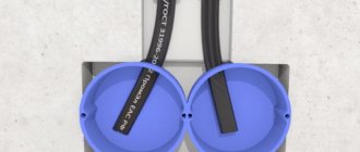
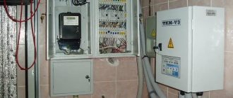
Selecting a single-phase electric meter
When choosing an electricity meter, we were guided by the following criteria:
Since we live in a modern world, we therefore wanted to have a modern electricity meter with an electronic display. In the store we were offered a single-phase multi-tariff meter Energomera CE 102
Single-phase multi-tariff meter Energomera CE 102
It fully meets our selection criteria, here is a list of its characteristics:
Connection diagram for Energomera CE 102 counter
Meter connection diagram