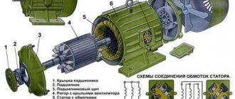
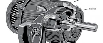
Three-phase asynchronous motors have found the widest application in industry and other fields. Modern equipment is simply impossible to imagine without these units. One of the most important components of the operating cycle of machines and mechanisms is their smooth start and the same smooth stop after completing the task. This mode is provided by using frequency converters. These devices have proven to be most effective in large, high-power electric motors.
With the help of frequency converters, inrush currents can be successfully adjusted, with the ability to control and limit their magnitude to the required values. To use this equipment correctly, you need to know the operating principle of a frequency converter for an asynchronous motor. Its use can significantly increase the service life of equipment and reduce energy losses. Electronic control, in addition to soft start, provides smooth adjustment of the drive in accordance with the established relationship between frequency and voltage.
What is a frequency converter
The main function of frequency converters is to smoothly regulate the rotation speed of asynchronous motors. For this purpose, a three-phase voltage with variable frequency is created at the output of the device.
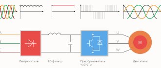
Frequency converters are often called inverters. Their basic principle of operation is to rectify the alternating voltage of an industrial network. For this purpose, rectifier diodes are used, combined into a common unit. Current filtering is carried out by high-capacitance capacitors, which reduce the ripple of the incoming voltage to a minimum. This is the answer to the question why a frequency converter is needed.
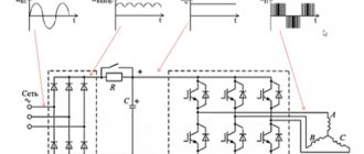
In some cases, the circuit may include a so-called energy drain circuit, consisting of a transistor and a resistor with high power dissipation. This circuit is used in braking mode to suppress the voltage generated by the electric motor. This prevents capacitors from overcharging and premature failure. As a result of the use of frequency drives, asynchronous motors are successfully replacing DC electric drives, which have serious disadvantages. Despite the ease of adjustment, they are considered unreliable and expensive to operate. During operation, the brushes constantly spark, and electrical erosion leads to wear on the commutator. DC motors are completely unsuitable for explosive and dusty environments.
U/F control method with encoder
If it is necessary to increase the accuracy of rotation speed control, an encoder is added to the control system. The introduction of speed feedback using an encoder allows you to increase the control accuracy to 0.03%. The output voltage will still be determined by the specified U/F pattern.
This control method is not widely used, since the advantages it provides compared to standard U/F functions are minimal. Starting torque, response speed and speed control range are all identical to standard U/F. In addition, when operating frequencies increase, problems with the operation of the encoder may arise, since it has a limited number of revolutions.
Operating principle of the frequency converter
Efficient and high-quality control of asynchronous electric motors has become possible through the use of frequency converters together with them. The overall design is a variable frequency drive, which has significantly improved the technical characteristics of machines and mechanisms.
The control element of this system is a frequency converter, the main function of which is to change the frequency of the supply voltage. Its design is made in the form of a static electronic unit, and the generation of an alternating voltage with a given variable frequency is carried out at the output terminals. Thus, by changing the voltage amplitude and frequency, the rotation speed of the electric motor is adjusted.
Asynchronous motors are controlled in two ways:
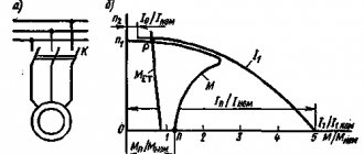
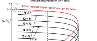
- Scalar control operates in accordance with a linear law, according to which amplitude and frequency are proportionally related to each other. The changing frequency leads to changes in the amplitude of the incoming voltage, affecting the torque level, efficiency and power factor of the unit. The dependence of the output frequency and supply voltage on the load torque on the motor shaft should be taken into account. In order for the load torque to be always uniform, the ratio of the voltage amplitude to the output frequency must be constant. This balance is precisely maintained by the frequency converter.
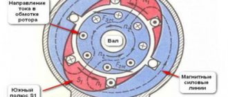
- Vector control keeps the load torque constant throughout the entire range of frequency adjustments. Control accuracy increases and the electric drive responds more flexibly to changing output loads. As a result, the motor torque is directly controlled by the converter. It must be taken into account that the torque is formed depending on the stator current, or more precisely, on the magnetic field it creates. Under vector control, the phase of the stator current changes. This phase is the current vector that directly controls the torque.
Control methods
Many people working in the field of automation, but not closely involved in the development and implementation of electric drive systems, believe that electric motor control consists of a sequence of commands entered using an interface from a control panel or PC. Yes, from the point of view of the general hierarchy of control of an automated system, this is correct, but there are also ways to control the electric motor itself. It is these methods that will have the maximum impact on the performance of the entire system.
For asynchronous motors connected to a frequency converter, there are four main control methods:
- U/f – volts per hertz;
- U/f with encoder;
- Open-loop vector control;
- Closed loop vector control;
All four methods use PWM pulse width modulation, which changes the width of a fixed signal by varying the width of the pulses to create an analog signal.
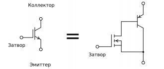
Pulse width modulation is applied to the frequency converter by using a fixed DC bus voltage. Insulated gate transistors (IGBTs) generate output pulses by rapidly opening and closing (or rather switching). By varying the width of these pulses at the output, a “sinusoid” of the desired frequency is obtained. Even if the shape of the output voltage of the transistors is pulsed, the current is still obtained in the form of a sinusoid, since the electric motor has an inductance that affects the shape of the current. All control methods are based on PWM modulation. The difference between control methods lies only in the method of calculating the voltage supplied to the electric motor.
In this case, the carrier frequency (shown in red) represents the maximum switching frequency of the transistors. The carrier frequency for inverters is usually in the range of 2 kHz - 15 kHz. The frequency reference (shown in blue) is the output frequency reference signal. For inverters used in conventional electric drive systems, as a rule, it ranges from 0 Hz to 60 Hz. When signals of two frequencies are superimposed on each other, a signal will be issued to open the transistor (indicated in black), which supplies power voltage to the electric motor.
Setting up a frequency converter for an electric motor
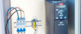
In order for the frequency converter for an asynchronous motor to fully perform its functions, it must be correctly connected and configured. At the very beginning of the network connection, a circuit breaker is placed in front of the device. Its rating must match the amount of current consumed by the motor. If the frequency generator is intended to be operated in a three-phase network, then the machine must also be three-phase, with a common lever. In this case, if there is a short circuit in one of the phases, you can quickly turn off the other phases.
The actuation current must have characteristics that fully correspond to the current of an individual phase of the electric motor. If the frequency converter is planned to be used in a single-phase network, in this case it is recommended to use a single circuit breaker, the rating of which should be three times the current of one phase. Regardless of the number of phases, when installing a frequency switch, the machines should not be connected to a break in the ground or neutral wire. It is recommended to use direct connection only.
If the frequency converter is correctly configured and connected, its phase wires must be connected to the corresponding contacts of the electric motor. The pre-windings in the motor are connected in a star or delta configuration, depending on the voltage supplied by the converter. If it matches the smaller value indicated on the motor housing, then a delta connection is used. At higher values, a star circuit is used.
Next, the frequency converter is connected to the controller and control panel, which is included in the delivery package. All connections are made in accordance with the diagram given in the instruction manual. The handle must be in the neutral position, after which the machine turns on. Normal activation is confirmed by an indicator light on the remote control. In order for the converter to work, the RUN button, programmed by default, is pressed.
Vector feedback control
Feedback vector control uses the same control algorithm as open-loop VAC. The main difference is the presence of an encoder, which allows the variable frequency drive to develop 200% starting torque at 0 rpm. This point is simply necessary to create an initial moment when moving off elevators, cranes and other lifting machines, in order to prevent subsidence of the load.
The presence of a speed feedback sensor allows you to increase the system response time to more than 50 Hz, as well as expand the speed control range to 1:1500. Also, the presence of feedback allows you to control not the speed of the electric machine, but the torque. In some mechanisms, it is the torque value that is of great importance. For example, winding machine, clogging mechanisms and others. In such devices it is necessary to regulate the torque of the machine.
Caring for the Transducer
To extend the service life of the inverter, you should take proper care of it:
- Monitor the accumulation of dust on the internal elements and promptly clean the device using a compressor.
- Make sure that the components used in the mechanism are working properly and replace them if the need arises.
- Maintain adequate operating temperature (no more than +40°C) of the mechanism and voltage level on the control bus.
- Regularly (at least once every 3 years) update the layer of thermal paste on the power components of the device.
- Maintain moderate humidity levels if possible.
Main selection criteria
When choosing a frequency converter and designing an electric drive with frequency control, you should pay attention to the following factors:
- Purpose. The modern electrical market now offers models designed for the operation of elevators, pumping equipment and ventilation systems, as well as universal action and general industrial use. In addition, there are specialized frequency generators with limited adaptation capabilities, designed for specific technological devices and processes;
- Management methodology and support for various types of communication protocols. Modern emergency situations are often integrated into complex and remotely controlled automated systems, so they must be equipped with a microcontroller to provide communication via one or more protocols compatible with the specific process control system used;
- Overload capacity and power. It is recommended to use frequencies with a rating that is 15-30 percent higher than the declared electrical power of the electric motor. Peak loads and starting currents of the electrical installation should also be taken into account in order to avoid overheating and failure of the converter itself, as well as the equipment operating under its control;
- Accuracy and adjustment range. The frequency must vary with accuracy and intervals that meet the requirements of a particular technical process. Scalar type frequency drivers allow you to set a value from one to ten. For a wider range, vector-type devices are used;
- Electromagnetic compatibility characteristics. The frequency converter itself creates electromagnetic interference and is susceptible to its influence, so the model must be selected in accordance with the installation conditions. For this, various filters and shielded cables are used. Sometimes frequency drives are even installed in a separate room, protected from the adverse operating conditions of the electric drive itself;
- Possibility of emergency shutdown of the power unit in case of overload, overheating, phase imbalance and other non-standard operating modes;
- The presence of situational automated control, when the synchronization of the operation of electrical equipment is carried out in accordance with the achievement of a certain value of one or more technological characteristics;
- Number of inputs/outputs for connecting various monitoring and remote control devices. To ensure the ability to upgrade an existing or planned system, it is recommended to select converters that have an excessive number of discrete and analog connectors. It is also desirable that they have integrated memory and the ability to compile a log of current and past events;
- Rated parameters of current and voltage. They are selected in accordance with the characteristics of the existing electric motor.
When choosing an industrial frequency converter, special calculation techniques are also used to minimize the likelihood of error. Therefore, it is advisable to entrust the selection of control devices for expensive equipment to specialists. A correctly selected frequency converter also allows you to significantly save energy and increases the efficiency of the technical process as a whole.