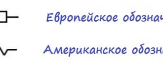
In accordance with the operating rules for electrical installations, any cable line must have digital and/or letter designations. Often, when an electrical circuit includes several parallel conductors, a combined alphanumeric system is used. In such a situation, the cable tag of each core contains the same numerical value, but different letters of the Cyrillic or Latin alphabet.
The cable sleeve and exposed wires must be marked with tags indicating the number, line name, operating voltage, cross-sectional area and brand of electrical components used. All tags are characterized by resistance to negative environmental factors. The maximum allowable distance between tags is 50 m.
Purposes of wire markings
This process can significantly simplify electrical installation work, planned or emergency repairs, and maintenance of facilities and cable lines during operation. Another functional purpose is to reduce the likelihood of emergency situations and accompanying injuries to working personnel.
The cable is marked during the manufacturing process. The manufacturer must choose the color for the insulating sheath of the wire in accordance with international or domestic standards specified in PUE, PTEEP, GOSTs and other documentation. The data displayed on the outer sheath of the cable indicates information on several parameters:
- number of wires;
- cross-sectional area of the entire cable;
- insulating materials used;
- wire materials, etc.
Such marking, although necessary, is not sufficient to increase safety during the operation of cable lines. Based on it, maintenance specialists will not be able to draw clear conclusions about the purpose of the entire system or a specific section of electrical wiring. Therefore, when performing electrical installation work, additional abbreviations are applied to the cable, adding information about the purpose of the circuit to the characteristics.
Thanks to this, tags with the following data appear on the insulation:
- cable brand;
- purpose;
- the object associated with it;
- line length and other information if necessary.
Cable tags greatly simplify such marking, making it convenient and as fast as possible. They are selected depending on the diameter, characteristics and insulating materials on the wire. They may differ in a number of parameters, but have a common purpose and are capable of storing inscriptions for long periods of use.
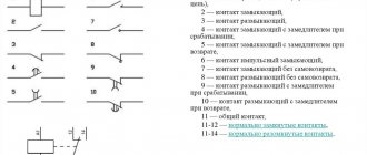
Designation of special cable characteristics
Helps to understand the special performance characteristics of the cable. Let's consider them according to GOST:
- “A” means that the cable is paved;
- “B” has armor tapes;
- “G” is a flexible wire without protection;
- “K” is armored with round wire;
- “T” is made for use on pipe bases;
- “O” received additional protection in the form of braiding.
Let us note the designation frls, since although it is added at the end, it provides information about combustion resistance, which is important for fire safety. It is divided into two abbreviations
FR indicates the level of fire resistance, and LS indicates the small amount of smoke produced when ignited.
Now you know how to correctly decipher cables or wires and can understand their markings. This will help in various situations related to laying electricity to buildings or creating wiring inside them using your own efforts.
Requirements for types and methods of attaching tags
In addition to the placement of tags, all information about the markings produced on cable lines and communication devices is recorded in a special journal. Such records are regularly updated depending on changes that have occurred in the network structure.
Like cable, tags are made into specific shapes from a variety of materials. These can be ordinary labels, self-adhesives, plastic seals or polymer products used for high-quality and reliable marking of a bundle of several cores or one wire.
Ley Line Markers
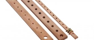
In accordance with GOST, plastic plaques are made in square, round or triangular shapes. They are used in open areas of cable routes and circuit components. The tags have two holes through which the wire or core should be threaded, after which it is securely clamped and fixed in the desired position.
For lines whose voltage does not exceed 1000 V, square tags are used. If the operating voltage is above 1000 V, then round plastic plaques are used. Triangular products are required for control power lines.
Tags for low power circuits
For such purposes, small plates made of polymer materials can be used, which indicate information about the electricity consumption of the circuit subscriber and other data.
Important! Cable tags should even be used for hidden lines located inside pipes, manholes and blocks.
Control cable
Control cable marking:
- “A” – aluminum or copper conductor, if there is no aluminum conductor.
- “B” – (second) PVC insulation.
- “B” – (third) PVC shell.
- “P” – polyethylene insulation.
- “Ps” – self-extinguishing polyethylene insulation.
- “G” – there is no protective cover.
- “R” – rubber insulation.
- “K” – (second or first letter) control cable.
- “KG” – flexible cable.
- “F” – fluoroplastic insulation.
- “E” - if at the beginning, then this is an electrical cable, the marking of which says that it is suitable for standard conditions, and if at the end or in the middle, then it is a shielded cable that is used to protect against electromagnetic radiation.
Main types of cable markers
A marking tag in accordance with international standards must be installed on open cable routes and power installations. If the wire is laid in structures specially designed for this purpose, then the distance between the markers can be 50-70 m. You cannot do without them in a number of other cases:
- when the route crosses various obstacles that make visual inspection difficult (interfloor ceilings, walls, partitions), then tags are placed on each side of the obstacle passed (for example, on both sides of the wall);
- at points where the direction of the cable line changes;
- in places where input or output from other structures is carried out.
Many manufacturers and electricians prefer cable tags made of plastic, since such material can withstand moisture for a long time without changing its properties.
Form of marking tags
The rules and regulations indicate information on the forms of tags, which were described above:
- triangular - installed in cable lines for control or signaling purposes;
- square – for power lines with voltage up to 1 kV;
- round – over 1 kV.
Label sizes
The most common brands of cable tags are U-134, U-135, U-136 and U-153. Let's compare their sizes and, depending on the data obtained, draw conclusions on possible use in systems:
- U-134 is used to mark power lines with voltages not exceeding 1000 V. The square tag with an area of 55x55 mm is equipped with two 11x3.5 mm grooves for fixing with a cable binder.
- U-135 is suitable for indicating information on electrical circuits with voltages over 1000 V. Round products with a diameter of 55 mm and similar grooves for cable binders.
- U-136 is used for marking signal and control wires. The triangular product has equal sides 62 mm long each. There are two slots for a cable binder of the same size.
- U-153 is used for power lines with voltages up to 1000 V. A square product with a length of 28 mm and a 5 mm hole is attached using a special wire.
Important! Many organizations either ignore the cable tagging process or perform it using free-form tags. The consequences of both decisions can cause frequent emergencies and injury to operating personnel.
Color coding of wires and cables
Generally accepted standards and rules for color marking the insulating sheath of wires allow you to quickly and accurately determine the operating parameters of a cable and understand in which systems and devices it can be used. The color marking regulations are prescribed by PUE and GOST.
It is noteworthy that the designation system will be different for cable networks with alternating current or direct current. Often the cable is made in different colors. Instead of a shell, color marking can be done using heat-shrinkable tubes (cambrics). Another option is colored electrical tape. The choice of color for phase and neutral wires should always be different!
For three-phase alternating power lines, the buses should be marked as follows:
- first phase – yellow;
- the second is green;
- the third is red.
In DC cable runs, color designations are chosen according to the charge, which can be positive or negative. In the first case, a wire with a red braid is selected, in the second, a wire with a blue braid. The system does not support phase and neutral wires, and for the middle wire a light blue conductor is usually used.
For power installations with voltage up to 1 kV and neutral, the following marking is carried out:
- working neutral wire – blue;
- grounding – yellow-green;
- combined zero – yellow-green with blue markers (or blue with yellow-green markers);
- phases - red, black and other colors depending on the quantity.
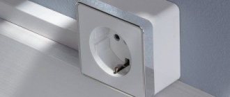
It is noteworthy that the wiring inside electrical appliances is red, in sockets - brown.
Correct Conductor Identification
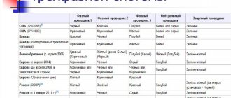
As I already wrote above, we take the latest GOST 33542–2015 officially implemented in Armenia, Belarus, Kyrgyzstan, Moldova, Russia and Tajikistan, then we find table A.1 there, which clearly regulates the colors, alphanumeric and graphic designations used for identification conductors and terminals of electrical equipment. And we use it!
Table A.1. Start. GOST 33542–2015
End of table A1 GOST 33542–2015
About IEC 60445:2017
This standard was released in August 2022 and replaced IEC 60445:2010, on the basis of which, as we know, GOST 33542-2015 was created. This standard has extremely important changes compared to IEC 60445:2010:
- the positive pole conductor is prescribed to be marked in red;
- negative pole conductor – white;
- functional grounding conductor – pink;
- Amendment 1, in particular, corrected two letter color designations in Table A.1. For brown color, the designation "BR" is replaced by the correct designation "BN", for gray color the designation "GR" is replaced by the designation "GY".
According to GOST 33542, the positive pole conductor is designated in brown, and the negative pole conductor is marked in gray.
Therefore, it is better to take this into account now. And the GOST 33542-2015 standard will be revised over time and brought into compliance with IEC 60445:2017.
AC electrical circuits
For example, we will determine what color the insulation of conductors in the electrical wiring of individual residential buildings and apartments should be.
We know that in three-phase electrical installations of buildings with TN-CS and TT system grounding types, 5 conductors are used: L1, L2, L3, N, PE. And if the electrical installation is single-phase, then 3 types of conductors are used: L, N, PE. These conductors should be marked with strictly defined colors.
In three-phase electrical installations in buildings, most electrical circuits are single-phase. The color of the insulation of the phase conductor of a single-phase electrical circuit must match the color of the insulation of the phase conductor of the three-phase electrical circuit to which it is connected.
For the phase conductor of a single-phase electrical circuit of a single-phase building electrical installation, the preferred color is set to brown. Therefore, the insulation of phase conductors in single-phase electrical circuits of single-phase electrical installations in buildings must be brown .
According to the requirements of GOST 33542-2015, the neutral conductor should be identified in blue. Therefore, the insulation of neutral conductors in all electrical circuits of single-phase and three-phase electrical installations in buildings must be blue .
According to the requirements of GOST 33542-2015, the protective conductor should be identified by a combination of yellow and green colors. Therefore, the insulation of protective conductors in all electrical circuits of single-phase and three-phase electrical installations in buildings must be yellow-green .
Then, according to GOST 33542-2015, we obtain the following cheat sheets: for three-phase and single-phase electrical installations of buildings (AC electrical circuits):
It should be noted here that phasing is not implied by these colors (brown, black and gray). This means that you can, for example, mark conductor L1 not only with brown insulation, but also with gray or black.
DC electrical circuits
As a result: you should buy the cable or wire that has the proper color identification of the cores in order to meet the requirements of modern GOST 33542-2015.
Wire and cable marking methods
When choosing marking products, electricians are guided by operating conditions, capabilities and technical parameters of tags, availability of the necessary equipment and manufacturing materials.
Before installing the wire
In many situations, cable markings are placed on routes after installation. However, in some cases it becomes necessary to do this much earlier. The most obvious example is confined space or working at dangerous heights.
In such situations, the following marking products can be used:
- PVC tubes and cambrics of different diameters, on which information about the line is printed (they can be additionally protected with transparent tape, which simplifies fixation and increases protection);
- heat shrink tube for insulation;
- A simpler and cheaper method is to write the information on a piece of thick paper, attach it to the cable and secure it with transparent tape or a clamp.
After installing the wire
If a wire or cable is located in a switchgear, then the designations are applied using one of the following methods:
- Before connecting the contact tracks to the wires, polyvinyl chloride cambrics and heat-shrinkable tubes are put on the latter.
- A self-laminating marker is a small plate, on one side of which an adhesive coating is applied for fixing to the cable, and on the other there is a matte surface for various inscriptions. The tag must be glued to the insulation and additionally wrapped with transparent tape (special electrical tape). The selected materials can withstand high temperatures and are characterized by resistance to aggressive environments.
- Cable tags are often the best option. The products are made of polymer materials and can be attached to the cable sheath in several ways. Plastic withstands high temperatures, protecting inscriptions with important information. The sizes, shapes and contents of tags are selected in accordance with PUE, PTEEP and SNiP.
- For small diameter cables, polymer flags with standard markings can be used.
- The sleeve and container involve the use of a plastic carrier that is attached to the wire, after which a marker with printed symbols is placed inside it.
- Clips and rings - for fixing with letters and numbers up to three or four characters.
- Self-adhesive nylon markers.
Rules and standards for marking wiring in electrical panels
The colors for marking the wiring were chosen for a reason. All the variety of colors comes down to one standard - standard rules. They are prescribed in the rules for technical operation of consumer electrical installations (PTEEP). It states that the conductors of electrical wires must be designated by color or letters and numbers, and the cabinet itself also requires designations. You can find out what types of wire color markings exist in our article.
The PUE states that:
- The electrical panel must have a name. This name is indicated on the body. In the electrical panel of the apartment it does not need to be marked with inscriptions. But for a private house, when the shield is placed on a pole, this is necessary.
- When installing it, you must leave a sheet inside the panel where all consumers (sockets and lamps) are indicated in table form.
- Also, inside there should be an assembly diagram for the input panel. This rule applies only to the device that was purchased assembled.
Note: if an electrician assembles a panel or cabinet, then you should definitely take the assembly diagram from him.
According to the same rules and PUE:
- Chapter 2.3. PUE clause 2.3.23. “Each cable line must have its own number or name...”.
- PTE EP clause 2.4.2 “Openly laid cables, as well as all cable couplings must be provided with tags.”
- There is marking on the circuit breakers or on the information board of the installation indicating the wiring group. Also, according to the rules, the serial number and name of the room or the purpose of the group (for example, a kitchen or an air conditioner) must be indicated.
- In the event that there is no space for recording on a modular device, marking with the purpose of this installation is made in the table and passport, which each cabinet must have.
According to GOST, wires are designated:
- In accordance with GOST 23594–79 (marking), the wire or cable is marked with tags or PVC tapes. PVC and heat-shrinkable tubes can serve as tags.
- The inscriptions on the label are written in a legible font and must be clearly visible. The length of the tag itself should not be less than 25 mm.
- According to the standards, markings can be applied to a wire or cable (to its insulation). Only on condition that such an inscription will be clearly visible.
We have figured out the basic rules for applying identification marks. Now let's look at how you can mark wires during installation.
Alphanumeric designations
GOST specifies regulations for marking the external insulation of cable lines, thanks to which cords, cables and wires can be distinguished from each other. If there are no markings on the braid or they are not sufficient for maintenance and safety, then special tags with additional data are attached to the route.
According to the rules and recommendations prescribed in GOST, a wire is a product consisting of one or more cores, which are protected with insulation along their entire length. The cores can be produced without insulation. A cable is defined as several conductors insulated separately from each other, placed under a single sealed sheath made of metal or polymer materials. A cord consists of two or more flexible conductors that are connected together by twisting or braiding. The cores are fixed along their entire length, and the braid is made from non-metallic materials.
All cables are divided into several groups:
- power;
- signaling and control;
- installation;
- radio frequency;
- connected.
You can decipher the alphanumeric symbols on the insulation yourself.
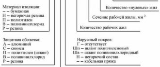
The first letter in the abbreviation indicates the material the core is made of. The letter “A” at the beginning indicates that the current-carrying conductor is made of aluminum. The absence of such a letter means that it is made of copper.
The second letter indicates the scope of application of the product. If the second letter in the abbreviation is missing, then such a cable is considered to be power.
The third letter is used to indicate the degree of flexibility of the product. Its absence indicates a single-core wire, the presence of the letter “G” indicates a flexible multi-core wire.
The fourth letter allows you to designate the material used to make the insulation. Windings are made from different materials, so more specific designations are used for it.
The fifth letter indicates the material used to make the outer shell and the presence or absence of an armored hull.
The sixth letter can be used to indicate the protective cover, the purpose of the layer and the structure as a whole.
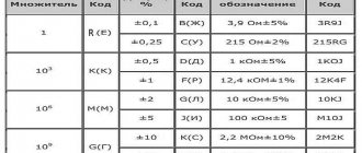
Thanks to capital letters, you can indicate certain features of the cable line, the presence of certain properties. After the letter designations there are numbers. The first number indicates the operating voltage (“1” – 1 kV, without a number – 600 V), the second – the number of cores (1-37), the third – cross-sectional area.
Types of cable products
You need to clearly understand the differences between a wire and a cord and a cord and a cable. Marking of wires and cables is carried out according to one GOST.
A wire is a product made from one or more cores twisted together. Products are produced with or without applied insulation.
Insulated cable
Widely used in the production of electric motors, generators and other types of industrial products.
The main area of application of a flexible cord is connecting various electrical appliances for household and industrial purposes to the network.
Decoding the marking allows you to accurately determine the scope of application of the product. The range of manufactured cables is divided into the following groups:
- power;
- control;
- radio frequency;
- management;
- communications.
For each type of product, GOST has been developed, which regulates the technical characteristics and operating conditions of each product.
Cable type VVG is not used in communication networks. In the same way, the use of the coaxial standard in power supply systems is prohibited.
According to building codes and regulations, each wire laid in a tray must have tags that are located every 50 meters.
Power
This type of product includes VVG and SIP wires. They are used in power, lighting and household circuits.
Types of power cables
GOST prescribes that wiring in domestic premises should be carried out with a cable made of copper conductors.
For special conditions, armored products are installed in mines and underground galleries.
Tests
These products are used in remote control systems to power electrical devices.
The number of conductors, according to GOST, varies from 4 to 37.
Control cable example
Labels with the prescribed information are attached to both ends of the cable.
Radio frequency
Cables are produced to transmit high-frequency signals from one electronic device to another.
Coaxial type product.
RF cable device
Copper inner wire.
On top of the insulation, a second conductor and a plastic protective sheath are applied.
Management
The products are used in remote control structures for various mechanisms.
Control cable example
Unlike the coaxial type, they have a number of current-carrying cores from 3 to 108.
Connections
A special type of cable is used to transmit information and communication signals between subscribers.
The number of copper cores is determined by the purpose of the cable.
High frequency communication cable
The product is divided into two types - low-frequency and high-frequency.
Marker fastening
Cable tags can be attached to wires using various fasteners. The most common are synthetic thread, plastic tapes with a latch, wire with an anti-corrosion coating, clips, etc. If you need to use ordinary steel wire for fastening, then it should first be coated with a protective layer of bitumen or paint to prevent corrosion. Ideally, you should use polyvinyl chloride insulated wire.
Using letters in combination with numbers
There is also an alphanumeric cable marking. Explanation:
- AVVGng 3×4 – three-core cable, aluminum. With a cross section of 4 squares. The shell and insulation consists of polyvinyl chloride, there is no protective cover and does not support combustion.
- PVG 3×2.5 – three-core copper cable. With a cross section of 2.5 square. There is polyethylene insulation. The protective shell consists of polyvinyl chloride, there is no protective cover.
- ASB 7×2.5 – seven-core cable, aluminum. With a cross section of 2.5 squares. The shell is made of lead and has armor.
That is, such marking shows the cross-section of the cores and their number.
How to mark
The most reliable method of marking cable lines is stamping. On the other hand, this method requires the presence of special equipment (a printer), which cannot always be used.
In many ways, the choice of a specific method depends on the material used to make the cable tag. You can also buy markers with already prepared symbols, sold in ribbons. They have cuts that allow you to quickly and accurately remove the desired label and fix it on the wire using an adhesive surface.
The inscriptions are made from waterproof paint or ink. If the electrical circuit is installed in rooms with high humidity levels or is constantly exposed to an aggressive environment, then the marking is applied by milling, punching, burning or stamping on plastic/metal.
For dry rooms with good ventilation or air conditioning, you can get by with marking using standard means - a pencil or felt-tip pen.
Common labeling mistakes
Let's list three main mistakes:
- The most common one is caused by novice electricians or experienced specialists due to inattention. In the process of screwing the wire to the shield and terminals, the craftsmen simply forget to put a heat-shrinkable tube with markings (tube) on the wires. Because of this, you have to unscrew the attached wiring and put the products on again.
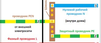
- Often craftsmen confuse the PEN conductor with a grounding cable. The fact is that both elements have identical color markings, so you need to inspect them more carefully.
- If the panel is located outside the site, then it is necessary to conclude an agreement with the electrical energy supplier. You must have on hand technical documentation with a diagram and confirmation of compliance with the requirements of the PUE, PTEEP and other regulatory acts. Otherwise, you may face claims from Rostekhnadzor.
Let's summarize: in accordance with the requirements and regulations prescribed in international and domestic standards, all power installations and cable lines without exception must be marked. The need for marking is not affected by either the voltage values or the location of installation (laying) of the circuit.
Qualified specialists will agree to carry out repair work and engage in maintenance of emergency areas only if sufficient information about the parameters of the line is provided. This is exactly what is contained on the cable tags.
Designation of cable products:
Cables are divided according to the following characteristics:
- according to the material of current-carrying conductors:
);
);
- insulation made of polyvinyl chloride plastic, including reduced fire hazard ( B
); - insulation made of cross-linked polyethylene ( PV
); - insulation from polymer compositions that do not contain halogens ( P
);
- unarmored ( G
), - armored: armor made of galvanized steel tapes ( B
), armor made of aluminum tapes or aluminum alloy (
Ba
), armor made of round galvanized steel wires (
K
), armor made of aluminum wires or aluminum alloy (
Ka
);
- made of polyvinyl chloride plastic, including reduced flammability or reduced fire hazard: outer shell ( B
), protective hose (
Shv
); - made of polyethylene: protective hose ( Шп
); - from polymer compositions that do not contain halogens: outer shell ( P
);
- without screen ( no designation
); - with screen ( E
);
- flame retardant when installed alone ( no designation
); - flame retardant during group installation ng: for category A - ng(A)
, for category B -
ng(B)
; - flame retardant when laid in groups, with reduced smoke and gas emission ng(A)-LS
; - do not propagate fire when laid in groups and do not emit corrosive gaseous products during combustion and smoldering ng(A)-HF
; - fire-resistant, flame retardant when laid in groups, with reduced smoke and gas emissions ng(A)-FRLS
; - fire-resistant, non-flammable when laid in groups and not releasing corrosive gaseous products during combustion and smoldering ng(A)-FRHF
;
- round ( no designation
); - flat ( P
);
- single-wire ( o
); - stranded ( m
); - round ( k
); - sectoral or segmental ( c
).