Hello, dear readers of the site. In the previous article, we figured out what connecting wires and electrical communication lines are and how they are indicated on electrical diagrams. In this article we will talk about a resistor , or as in the old fashioned way it is also called resistance
.
Resistors are the most common elements of electronic equipment and are used in almost every electronic device. Resistors have electrical resistance
and serve to
limit the passage of current
in an electrical circuit. They are used in voltage divider circuits, as additional resistances and shunts in measuring instruments, as voltage and current regulators, volume controls, sound timbre, etc. In complex devices, the number of resistors can reach up to several thousand pieces.
What is a resistor?
Special components called resistors are designed specifically to create the precise amount of resistance added to a circuit. They are typically made from metal wire or carbon and are designed to maintain a stable resistance value over a wide range of environmental conditions. Unlike lamps, they do not emit light, but they do produce heat because they dissipate electrical energy in a working circuit. Typically, however, a resistor is not designed to generate useful heat, but simply to provide a precise amount of electrical resistance.
Literature
- Sensors and Controls. SOLUTIONS GUIDE. Bourns, 2003;
- Bourns® Trimpot® Product Catalog. – Bourns, 2004;
- Selecting the Appropriate Position Feedback Sensor for Factory Automation Valve Designs. WHITE PAPER. Bourns, 2011;
- https://www.bourns.com/.
Obtaining technical information, ordering samples, ordering and delivery.
•••
Symbols and resistor values in the diagram
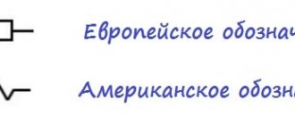
The symbol for a resistor in the diagram according to GOST is a rectangle measuring 4 mm x 8 mm. In English-language literature, the designation of a resistor in the form of a sawtooth line is common:
Figure 1 – Symbolic graphic designation of a resistor
Resistor ohm values are usually shown on the diagram as numbers next to the symbol, and if there are multiple resistors in the circuit, they will be labeled with a unique identification number such as R1, R2, R3, etc. As you can see, resistor symbols can be shown horizontally or vertically:
Figure 2 – Designation of resistor values in the diagram (150 Ohm and 25 Ohm resistors)
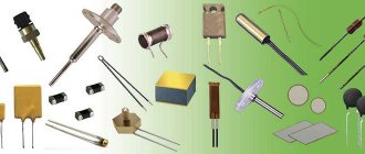
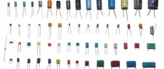
Below are some examples of resistors of different types and sizes:
Figure 3 – Examples of resistors
The diagram can also show that the resistor has a variable and not a fixed resistance. This may be for the purpose of describing an actual physical device designed to provide adjustable resistance, or it may be to show some component that simply has unstable resistance:
Figure 4 – Symbol of a variable resistor
In fact, any time you see a component symbol with a diagonal arrow drawn, it means that the component has a variable value rather than a fixed value. This "modifier" symbol (diagonal arrow) is a standard addition to the identification of electronic components.
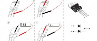
Digital markings on the resistor housing
SMD resistors, like those in the 0603 or 0805 packages, have their own way of displaying their value. There are several common marking methods that you will see on these resistors. They usually have three to four characters - numbers or letters - printed on the top of the case.
If all three symbols you see are numbers, you are probably looking at a resistor labeled like E24 . These markings actually bear some resemblance to the color banding system used on PTG resistors. The first two numbers represent the first two most significant digits of the value, the last number represents the magnitude. Digital marking of resistors will look like this:
In the example image above, the resistors are labeled 104, 105, 205, 751, and 754. The resistor labeled 104 should be 100 kΩ (10×10 4 ), 105 would be 1 MΩ (10×10 5 ), and 205 would be 2 MΩ (20×10 5 ). 751 is 750 Ohms (75×10 1 ), and 754 is 750 kOhms (75×10 4 ).
Another common encoding system is E96 , and it is the most unusual of all. E96 resistors will be marked with three symbols - two numbers at the beginning and a letter at the end. The two numbers show the first three digits of the value, corresponding to one of the non-obvious values in this lookup table.
The letter at the end represents a multiplier corresponding to something in this table:
So resistor 01C is the best choice, 10k ohm (100x100), 01B is 1k ohm (100x10), and 01D is 100k ohm. This is easy, other codes may not be available. 85A from the picture above is 750 ohms (750x1) and 30C is actually 20 kohms.
Variable resistors
Variable resistors must have some physical means of adjustment, either a rotating shaft or a lever that can be moved to change the amount of electrical resistance. The photo below shows devices called potentiometers, which can be used as variable resistors:
Figure 5 – Potentiometer
Rev counter knobs from Bourns
For multi-turn variable resistors, Bourns suggests using specialized knobs with a rotation counting function (Table 8, Figure 12). In addition, the H-xx series have additional markings in the form of a scale for the angle of rotation of the handle.
Rice. 12. Knobs/revolution counters
Table 8. Knob/revolution counter parameters
| Parameter | Series | |||||
| H-46 | H-22 | H-23 | H-516 | CT-23 | CT-26 | |
| Speed | 0…20 | 0…15 | 0…15 | 0…15 | 0…10 | 0…10 |
| Display | Dial + speed | – | Speed | |||
| Divisions per revolution | 100 | 50 | 50 | 50 | 500 | 500 |
| Retainer | + | + | + | + | + | + |
| Diameter, mm | 46 | 22 | 22 | 22 | 27 | 28 |
| Depth, mm | 25 | 24 | 24 | 25 | 31,5 | 31,5 |
| Weight, g | 73 | 15 | 15 | 7 | 34 | 34 |
The main areas of application for these handles are control panels for industrial and medical electronics.
Rated power of resistors
Because resistors dissipate thermal energy as electrical currents through them overcome the "friction" of their resistance, resistors are also rated in terms of how much thermal energy they can dissipate without overheating and causing damage. Naturally, this rated power is indicated in physical units of measurement, “watts”. Most resistors used in small electronic devices such as portable radios are rated at 1/4 (0.25) W or less. The power rating of any resistor is roughly proportional to its physical size. Notice in the first photo of the resistors how the power rating relates to the size: the larger the resistor, the higher the power rating. Also note that resistance (in ohms) has nothing to do with size! While it may now seem pointless to have a device that does nothing other than resist electrical current, resistors are extremely useful devices in circuits. Because they are simple and so commonly used in the world of electricity and electronics, we will spend a lot of time analyzing circuits consisting of just resistors and power supplies.
Resistor noise and ways to reduce it
The intrinsic noise of resistive elements consists of thermal and current noise. Thermal noise caused by the movement of electrons in the conductive layer increases with increasing heating temperature of the part and the ambient temperature. When current flows, current noise is generated. Current noise, the value of which is significantly higher than thermal noise, is mainly characteristic of non-wire resistors.
Ways to deal with noise:
- The use in the circuit of types of resistors in which the noise is low due to manufacturing technology.
- Variable resistors are noisier than constant ones, so in the circuit they try to use elements with a variable resistance of a minimum value or not use them at all.
- Using retractors with more power than required by the technology.
- Forced cooling of the element by installing a nearby fan.
What are resistors useful for?
For a practical illustration of the usefulness of resistors, see the photo below. This is a picture of a printed circuit board: an assembly consisting of insulating layers of fiberglass laminate and a layer of conductive copper traces into which components can be inserted and secured using a low-temperature welding process called "soldering." The various components on this PCB are identified by printed labels. Resistors are designated by any label starting with the letter "R".
Figure 6 – Example of resistors on a printed circuit board
This particular circuit board is an addition to the computer called a "modem" that allows digital information to be transmitted over telephone lines. On the board of this modem you can see at least a dozen resistors (all with a nominal power dissipation of 0.25 W). Each of the black rectangles (called "integrated circuits" or "microcircuits" or "chips") also contains its own resistor array required for operation. Another PCB example shows resistors packaged in even smaller packages called SMD (“surface mount device”). This particular circuit board is the underside of a computer's hard drive; and again the resistors soldered to it are indicated by marks starting with the letter “R”:
Figure 7 – Example of resistors on a printed circuit board
There are over a hundred surface mount resistors on this PCB, and this number of course does not include the resistors built into the black "chips". These two photos should convince anyone that resistors (devices that “merely” prevent electrical current from flowing) are very important components in the field of electronics!
Installation method
According to installation technology, resistors are divided into output and SMD.
Output resistors
Radial output resistor
Axial output resistor
Designed for installation through a printed circuit board. The leads can be located axially or radially. Such parts were used in old audio and video equipment. Now they are used in simple devices and in cases where the use of SMD resistors is impossible for some reason.
The design of output resistors can be made of wire, metal film or composite.
What does a wirewound resistor consist of?
In wirewound resistors, the resistive component is a wire wound around a core. Bifilar winding (two parallel wires insulated from each other, or a regular two-core wire) reduces parasitic inductance. Leads made of stranded copper or brass plates are connected to the ends of the winding. To protect against moisture, mechanical damage and contamination, wire cuts are coated with inorganic enamel that is resistant to elevated temperatures.
What is the difference between a metal film resistor and a wirewound resistor?
In a metal film resistor, the resistive element is not a wire, but a film made of a metal alloy. The resistive components (wire or film) in the resistor are made of alloys with high resistivity: manganin, constantan, nichrome, nickel.
SMD resistors
SMD resistors (or chip resistors) are designed for surface mounting and do not have pins. These miniature parts of low thickness are made in rectangular or oval shapes. They have small contacts soldered into the surface. Their advantages are saving space on the board, simplifying and speeding up the board assembly process, and the ability to use them for automated installation.
SMD resistors are manufactured using film technology. They can be thin- or thick-film. A resistive thick or thin film is applied to an insulating substrate. The substrate performs two functions: a base and a heat-removing component.
What are chip resistors made of?
Thin-film elements, which have special requirements for moisture resistance, are made of nichrome. In the production of thick-film models, ruthenium dioxide, lead and bismuth ruthenites are used.
"Load" on circuit diagrams
In diagrams, resistor symbols are sometimes used to illustrate a general type of device that does something useful with electrical energy. Any unspecified electrical device is usually called a load, so if you see a diagram with a resistor symbol labeled "load", especially in an educational circuit diagram explaining some concepts unrelated to the actual use of electricity, that symbol may simply be some kind of shorthand something even more practical than a resistor.
Resistor Circuit Analysis
To summarize what we've learned in this article, let's analyze the following diagram, determining what we can from the information provided:
Figure 8 – Example circuit
All we are given here to start with is the battery voltage (10 volts) and the current in the circuit (2 amps). We do not know the resistance of the resistor in ohms or the power it dissipates in watts. Recalling the formulas of Ohm's law, we find two equations that give us answers based on the known values of voltage and current:
\(R=\frac{E}{I} \qquad and \qquad P=IE\)
By substituting the known values of voltage (E) and current (I) into these two equations, we can determine the circuit resistance (R) and power dissipation (P):
\(R = \frac{10\V}{2\A} = 5\Ohm\)
\(P = (2\A)(10\V) = 20\W\)
For the given circuit conditions (10 V and 2 A), the resistor should be 5 ohms. If we were to design the circuit to operate at these values, we would have to use a resistor with a minimum power rating of 20 W, otherwise it would overheat and fail.
Types of connection of resistors in an electrical circuit
The effective operation of electrical circuit elements with a resistor depends on the correct choice of not only the resistance itself, but also the method of its connection in the circuit, which can be series, parallel or mixed.
Serial connection
Series connection of resistors
In such a circuit, each subsequent resistor is connected to the previous one, forming an unbranched circuit. The current in series-connected circuits is the same, but the voltage is different. The total resistance of several serially located "rezyuks" is determined very simply - by summing their values.
Formula: Rtot. = R1 + R2 +…+ Rn
The more elements in a series circuit, the greater the total resistance.
Parallel connection
Parallel connection of resistors
In a parallel connection, resistors are connected to each other by inputs and outputs. The voltage across these elements is the same, and the current is distributed between them. The more branches are formed, the more options for current flow and the lower the overall resistance.
Formula: Rtot. = 1/R1 + 1/R2 +…+ 1/Rn
Mixed compound
Mixed connection of resistors
With this method, options for connecting elements are combined. The resistance of each section with a certain type of connection is calculated according to the above rules.
Connecting several resistors in one circuit
If you don’t have the resistance of the required value on hand, you can get it by correctly connecting several resistors. So, if you need a resistance of 100 kOhm, and there are two resistive parts of 50 kOhm each, then you can connect them in series and get the desired result. A resistance of 100 kOhm can be obtained by parallel connection of 200 kOhm elements.
Materials from which resistors are made
Throughout the world you can find resistors made from a wide variety of materials, each of which has its own properties and specific applications. Most electronics engineers use the types below.
Wirewound resistors
Figure 9 - Wirewound Resistors
Wirewound resistors are made by winding high-resistance wire in a spiral around a non-conducting core. They are usually used where high precision or high power is needed. The core is usually made of ceramic or fiberglass and the resistive wire is made of nickel-chromium alloy, which is not suitable for applications above 50 kHz. The advantages of wirewound resistors are low noise level and resistance to temperature fluctuations. Resistors are available with resistance values from 0.1 to 100 kOhm and with accuracy from 0.1% to 20%.
Metal film resistors
Figure 10 - Metal film resistors
For metal film resistors, nichrome or tantalum nitride is usually used. The resistive material is usually a combination of ceramic material and metal. The resistance value is changed by cutting a spiral pattern into the film, much like carbon film, using a laser or abrasive. Metal film resistors are generally less stable with temperature changes than wirewound resistors, but cope better with higher frequencies.
Metal Oxide Film Resistors
Figure 11 - Metal Oxide Film Resistors
Metal oxide resistors use metal oxides such as tin oxide, which makes them slightly different from metal film resistors. These resistors are reliable and stable and operate at higher temperatures than metal film resistors. For this reason, metal oxide film resistors are used in applications requiring high wear resistance.
Foil resistors
Figure 12 - Foil Resistors
Developed in the 1960s, the foil resistor is still one of the most accurate and stable types of resistors you will find, used in applications with high precision requirements. The resistive element consists of a thin bulk metal foil, which is glued to a ceramic substrate. Foil resistors have a very low temperature coefficient of resistance (TCR).
Carbon composite resistors
Figure 13 - Carbon Composite Resistors
Until the 1960s, carbon composite resistors were the standard for most applications. They are reliable, but not very accurate (their tolerance cannot be better than about 5%). The resistive element of carbon resistors uses a mixture of fine carbon particles and a non-conductive ceramic material. The resistive substance is shaped into a cylinder and baked. The amount of resistance is determined by the dimensions of the case and the ratio of carbon and ceramics. Using more carbon in the process means lower resistance. Carbon composite resistors are still useful for certain applications due to their ability to withstand high power pulses, a good example application would be a power supply.
Carbon Film Resistors
Carbon film resistors are a thin carbon film (cut in a spiral to increase the resistive path) on an insulating cylindrical core. This design allows for a more accurate resistance value and also increases the resistance value. Carbon film resistors are much more accurate than carbon composite resistors. For applications requiring stability at high frequencies, special carbon film resistors are used.
Key Performance Indicators (KPI)
Key resistor performance indicators for each material can be found below:
Key resistor performance indicators by material
| Characteristic | Metal film resistors | Thick film resistors | Thin Film Resistors | Carbon composite resistors | Carbon Film Resistors |
| Operating temperature range, °C | -55 … +125 | -55 … +130 | -55 … +155 | -40 … +105 | -55 … +155 |
| Maximum temperature coefficient of resistance | 100 | 100 | 15 | 1200 | 250–1000 |
| Maximum voltage, V | 250–350 | 250 | 200 | 350–500 | 350–500 |
| Noise, µV per 1 V applied DC voltage | 0,5 | 0,1 | 0,1 | 4 | 5 |
| Insulation resistance, kOhm | 10 | 10 | 10 | 10 | 10 |
| Change in soldering resistance, % | 0,20 | 0,15 | 0,02 | 2 | 0,50 |
| Change in resistance when exposed to high temperature and humidity, % | 0,50 | 1 | 0,50 | 15 | 3,5 |
| Change in resistance during long-term storage, % | 0,10 | 0,10 | 0,00 | 5 | 2 |
| Change in resistance during operation for 2000 hours at a temperature of 70°C, % | 1 | 1 | 0,03 | 10 | 4 |
Summary
- Devices called resistors are designed to provide precise resistance values in electrical circuits. Resistors are rated by both their resistance (Ohms) and their ability to dissipate thermal energy (W).
- The rated resistance of a resistor cannot be determined by its physical size, although the size can give an approximate value for the power rating. The larger the resistor, the more power it can dissipate without being damaged.
- Any device that uses electricity to perform some useful task is usually called a load. Sometimes the resistor symbol is used in circuits to represent an unspecified load rather than an actual resistor.
Original article:
- Resistors
Determining the type by marking
The marking is adopted in accordance with GOST 11.074.009-78 and has its own interpretation.
The designation of alphanumeric resistor labels (from left to right) is as follows:
- letters RP – variable;
- numbers: 1 – non-wire, 2 – wire or metal foil;
- registration number;
- year of issue;
- FH type;
- nominal resistance value;
- letter of tolerance for deviation from the nominal value.
The number of marks applied depends on the size of the case, but the Rnom value is required.
Decoding the markings on the body
Variable resistors can be of different designs. It is allowed to install several variable resistive elements on one axis. They are used to adjust and adjust many electrical parameters.