The LED blinking program is perhaps the first program that novice radio amateurs write when learning the Arduino platform. This program is very simple and does not require connecting any additional devices to the Arduino board. But if you need to turn on some fairly powerful device using the Arduino board, then you can’t do without the help of a relay.
In this article, we will look at connecting a relay to an Arduino board and using it to flash an AC light bulb. In this project we will not use any special driver to control the relay (eg ULN2003) - we will use an NPN transistor for this purpose.
Relay module HL-52S for Arduino
As an example for this Arduino relay tutorial, we will be using the HL-52S 2 Channel Relay Module, which has 2 relays rated at 10A at 250 and 125V AC and 10A at 30 and 28V DC. The high voltage output connector has 3 pins, the middle one is the common pin, and as you can see from the markings, one of the other two pins is for a normally open connection and the other is for a normally closed connection.
On one side of the module we have 2 sets of contacts.
The first one has 4 pins, ground and VCC pin for powering the module and 2 input pins In1 and In2. The second set of pins has 3 pins with a jumper between the JDVcc pin and the Vcc pin. Attention ! With this configuration, the relay solenoid receives power directly from the Arduino board, and if anything goes wrong with the relay, the microcontroller may be damaged.
Automatic relay Bosch Cube. Pinout and description
These relays can provide different voltages and currents. The relay that will be discussed further provides a voltage of 12 V and a current of 20/30 A. That is, with closed contacts the current is 20 A, with open contacts - 30 A.
Also, on my relay the coil resistance is approximately 95 ohms.
The current needed for the coil is much greater than what the Arduino can provide, but it becomes quite sufficient after using the TIP122 transistor, which produces 5 A.
Schematic diagram
To better understand how to work with Arduino relays, let's look at the circuit diagram of the relay module in this configuration. So we can see below that the 5 volts from our microcontroller connected to the Vcc pin to activate the relay via an optocoupler is also connected to the JDVcc pin which powers the relay solenoid. So in this case we did not get any isolation between the relay and the microcontroller.
To isolate the microcontroller from the relay, we need to remove the jumper and connect a separate power supply for the solenoid to the JDVcc and ground pin. Now with this configuration the microcontroller has no physical connection to the relay, it simply uses the LED light of the optocoupler IC to activate the relay.
There is one more thing to note about this circuit diagram. The module input contacts operate in reverse order. As we can see the relay will be activated when the input pin is LOW because this way current can flow from VCC to the input pin which is low or grounded the LED will light up and activate the relay. When the input pin is HIGH, no current will flow, so the LED will not light and the relay will not be activated.
High voltage warning ! Before we continue with this tutorial, we warn you that high voltage will be used which, if used incorrectly, can cause serious injury or death. So be very careful what you do! The ArduinoPlus.ru project does not bear any responsibility for any of your actions.
Examination
Disconnect your USB cable from your personal computer and connect an external power supply to the Arduino and the relay. Give your microcontroller time to reboot. If everything was done correctly, you should hear a characteristic click of the relay, which will close and open the contact every two seconds.
PS In this project, a 12-volt car battery was used as a power source, but you can use another one.
Leave your comments, questions and share your personal experiences below. New ideas and projects are often born in discussions!
How to use the relay module with high voltage devices
First let's look at the circuit diagram. As described earlier, we will use the 5V adapter as a separate power supply for the electromagnet connected to the JDVcc and ground pin. The Arduino 5V pin will be connected to the Vcc pin of the module and pin 7 to the In1 input pin to control the relay. Now for the "high voltage" part we will need a plug, socket and a cable with two wires. One of the two wires will be cut and connected to the common and normally open pin of the module output connector. So in this configuration, when we activate the relay, we will have a closed and operational high voltage circuit.
Below we will touch on how to make a cable. We need a plug, socket and cable. Carefully cut the cable and cut one of the wires as shown in the picture below. We connect them to the normally open contacts of the relay module. We also connect the ends of the cable to the plug and socket.
Note ! Make sure you use wires other than the yellow and green ones as they are intended for ground.
The final cable, ready for use, is below. Before using the cable, make sure it is working properly. You can check this with a multimeter or test it on low voltage first.
Mini review: modules based on 12 V relays. Use in a homemade UMZCH.
Mini-review of relay modules, use in UMZCH. Purely out of greed (for the future), single-channel and two-channel relay modules for 12 V were ordered. The relay winding resistance is 400 Ohms.
1. Single channel module.
Since the seller did not bother to provide a diagram, I had to draw it after receiving it. This is what happened.
Scheme - hello. TTL levels cannot be controlled
(I almost burned the microcircuit by connecting its output to the module input).
Requires an open collector or open drain.
There is +11.3 V at the input of the circuit. When the input is shorted to ground, the relay is activated.
The modules (as well as the review) waited a year and a half before they got around to it.
For a single-channel module, a task was found: turning on a power amplifier (PA) synchronously with the Asus O!Play HDP-R1 multimedia player.
The idea is as simple as the mooing of a cow: when you turn on the player, 5 V power appears on its USB ports, which can be used for control. Yes, in hindsight I realized that I should have ordered modules with 5 V relays.
The result is this diagram:
The solid-state relay RKP1A (KR293KP1A) is necessary to maintain galvanic isolation between the zero of the player’s USB port and the PA ground. The relay contact group is parallel to the contacts of the UM power switch.
This is a feature of the setup.
Player - (HDMI cable) - TV (video only) Player - (optics) - SMSL DAC - Volume (PGA2311) - PA (pure terminal) - AC Thus, the player is galvanically isolated from the sound system.
Here it’s a no brainer that a relay with a 5 V winding would simplify the implementation. For now, here it is:
The three-pin connector is from the fan. RKP1A on the wires is hidden under electrical tape.
Test: applied 5 V from the power bank, everything works.
2. Dual channel 12V module.
The photo was honestly borrowed from the seller.
Why the devil did the developer use optocouplers is a mystery shrouded in darkness. The printed conductors are covered with black varnish, so I was too lazy to copy the circuit. The channels have a common zero (ground). At the inputs (similar to a single-channel module) there is a voltage of +9.6 V. For the relay to operate, the corresponding input must be “grounded” to ground.
The sensitivity (current) of each input is very high: it is enough to hang a 33 kOhm resistor (between the input and ground) for the relay to operate. The current is about 0.3 mA.
For the two-channel module, there was a proven speaker protection circuit from some Radio magazine of the 80s:
Two copies of this scheme (with different denominations) have been working in other minds (one since the 90s, the other since about 2012). The circuit was assembled in a simulator to optimize the operating threshold (module current 0.3 mA, equal to the base current of Q1).
R1 and C1 are 1st order low-pass filters: when a constant voltage appears, transistor U1 or U2 opens. The variable component (limiting case ~30 V (amplitude value), 20 Hz) is reduced by the low-pass filter to a value of ~0.5 V (i.e. below the threshold voltage for opening transistors U1 or U2). Since U2 is connected according to the circuit with OB, the sensitivity of the minus constant is slightly lower than that of the positive one. The protection is triggered when a constant voltage appears at the PA output of more than +0.75 V or less than minus 2 V
.
Protection board and two-channel module installed in the UMZCH housing:
Power supply - constant 12 V (from the same power supply from which the single-channel module operates).
Checking the functionality of the AC protection - 1.5 V AA battery (1.65 V at idle). I connected the protection board to the input of one channel (plus to the input): the relay worked; I connected the minus battery to the input, it also worked.
That's all. Subscribe to my tyrtrub channel. Read about the construction of the amplifier in the next issue. )) Health to everyone!
Cat basks in the sun
Source
All that remains is to write simple code for our Arduino relay and test the module to see how it will work. The code itself is quite simple, we will simply use pin 7 to control the relay, so we will define it as an output and create a program that will simply activate and deactivate the relay every 3 seconds. Here I will mention again that the module input works in reverse, so a low logic level on the input will actually activate the relay, and vice versa.
int in1 = 7; void setup() { pinMode(in1, OUTPUT); digitalWrite(in1, HIGH); } void loop() { digitalWrite(in1, LOW); delay(3000); digitalWrite(in1, HIGH); delay(3000); }
3 devices were tested based on this example. First a 100W light bulb, then a table lamp and a fan heater. All these devices operate on 220V. This way it is possible to control any high voltage device using Arduino or any other microcontroller. And of course the possibilities are endless, for example we can control devices using the TV remote control, Bluetooth, SMS, Internet and so on.
Automatic lamp or street lamp
Using a controller, relay and light sensor, you can make a simple automatic lamp. The controller will light the lamp at the moment when the light level on the sensor becomes less than the set value.
As a sensor we use a ready-made module based on a photoresistor. Let's connect all three devices according to the following diagram.
Schematic diagram
Layout appearance
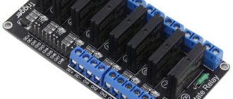
Connecting a solid state relay
The connection principle is simple. The device has control inputs (voltage is supplied to them with strict polarity) and an output for connecting a load. An important point is the quality of the connection. The screw method is used here (soldering is excluded).
To avoid damage to the SSR, it is important to prevent dust and foreign mechanical elements from coming into contact with the contacts. It is worth taking measures to prevent negative impacts on the device casing (on or off).
After switching on, do not touch the housing, which may be hot. Please note that the TSR is not located near flammable materials. In addition, during the connection process, make sure that the connections are completed without errors.
If, after switching on, the product reaches a temperature above 60 degrees Celsius, install a radiator on it for cooling (the reasons and features of this protective measure are discussed above).
If nothing is done, the device will stop working when it reaches 80 degrees Celsius. Control is carried out using a chain with various design options.
Operating principle
Knowing the design features of a solid-state relay, it is easier to understand the principle of its operation. Two signals interact in the device - control and controlled, which is ensured thanks to galvanic isolation.
In some SSR models, this function is performed by an optocoupler. The voltage that controls the device is also supplied to the LED.
The glow of the latter enters the photodiode, which leads to the appearance of a current, turning on an MOS or thyristor to control the connected device.
In addition, in the process of creating a circuit, it is possible to use special optoelectronic devices - opto- and photothyristors.
Differences and advantages of solid-state relays (compared to electromechanical ones)
When choosing an SSR, the buyer has a number of questions - why overpay for a solid-state relay, what are its advantages over standard electromechanical devices. Let's highlight the main advantages:
- Small dimensions, which eliminates problems with finding a place for installation.
- No noise or vibration. This is important if the device is installed in rooms where there are people.
- High switching speed.
- Long service life due to the absence of wear of the mechanical and electrical parts.
- Constant output impedance that does not change during its service life. In addition, contact groups are not subject to oxidative processes.
- There are no sudden voltage changes during the switching process.
- There are no sparks, which expands the scope of application. Its installation is allowed at facilities where there is an increased risk of explosions and fire.
- Low sensitivity to external factors, for example, the appearance of magnetic fields, vibrations, increased dust levels or magnetic fields.
- High level of resistance between output and input.
- Low energy consumption.
- A large number of switchings, which is not limited by the manufacturer. In reality it reaches 109.
Selecting a Solid State Relay
When purchasing a TTP, it is worth considering a number of features of the device, which will help you make the right choice. For comparison, classical devices are able to withstand overloads that occur for a short time and do not exceed one and a half or two times the rated current.
If you approach the issue of operation correctly, regular cleaning of contacts will suffice.
In the case of solid-state relays, the situation is worse. If the rated current parameter is exceeded by 1.5 times or more, the device can be discarded. That is why, when choosing an SSR to power an active load, it is worth taking a current reserve of two to four times.
If the product is planned to be used in the IM start-up circuit, this figure should be increased by six to ten times. With this approach, you will have to overpay, but it increases the service life of the connected device and the reliability of its operation.
Flaws
In addition to the positive qualities of solid-state relays, it is worth highlighting a number of disadvantages:
- When open, the product heats up due to the high resistance in the pn junction circuit. To avoid negative consequences in devices that pass high currents through themselves, it is necessary to provide cooling.
- When closed, the resistance increases and reverse leakage current appears (measured in mA).
- When taking the current-voltage characteristic, its nonlinear nature is noticeable.
- Some types of solid-state relays require strict polarity when connecting output circuits. This applies to those devices that are designed to operate in direct current conditions.
- In the event of a breakdown, there is a high risk of blocking the input contacts. The reason may be a breakdown of the power switch. For comparison, the contacts of classic relays (if they fail) remain open.
- Protection against erroneous operations caused by voltage surges is required. This is due to the high response speed.
- Solid-state relays pass current along the return path with a slight delay, which is due to the use of semiconductor elements in the circuit.
Types of solid state relays
SSRs are conventionally divided according to two criteria - the principle of operation and design features. To simplify the classification, we highlight the following options:
- By type of control signal - variable or constant I.
- According to the type of main (switched) voltage - constant or alternating.
- According to the number of phases (for alternating voltage) - one, three.
- According to the presence of reverse - provided, not provided.
- According to the subtleties of the design - on a DIN rail or on a surface.