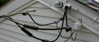
If you find yourself here, then you have a task: to introduce electricity into your private home. And of course there are many questions in my head: which cable to choose? Which introductory machine should I install? Which counter should I choose? And in the end, how to combine all this into one properly working system. We would like to share our experience of how we carried out air entry into our country house. Well, now let's look at all our steps and thoughts in order. What we had: on the street there was a concrete pole with main wires, aluminum wires were connected from it on twists, then they were connected to the output wire at the gander on the roof.
It was necessary to replace all this old stuff with something modern, and the best option to do this was using 2x16 SIP wires.
Entry into the house with SIP wire
Perhaps someone is not familiar with the abbreviation SIP, which stands for self-supporting insulated wire.
It was invented to replace conventional aluminum wires, which are sometimes tampered with by scrap metal collectors. In essence, this is an ordinary twisted aluminum wire, but now it is in insulation, which must be removed, and therefore SIP cables have become of no interest to metal assemblers.
To enter the house with SIP wire, we purchased the following fittings for SIP and other switching elements in the store:
- SIP wire 2x16 long - 12 meters;
- Anchor clamp for SIP cable 4x16 - 2 pieces;
- Branch piercing clamps - 2 pieces;
- Galvanized corner with holes - 1 piece;
- Sealed box with DIN rail - 1 piece;
- PVC corrugation with fastenings - 20 meters;
- Two-core copper cable AVVG 2x10 - 15 meters.
- Automatic switch EKF BA47-73 - 2 pieces.
From our side: a corner was installed on the gable of the house using a bolted connection, to which an anchor wedge clamp for SIP was attached.
Installation of SIP on the gable of a house
SIP anchor clamp
Since the SIP cable has polyethylene insulation, according to the PUE, it cannot be brought into the house!
7.4.36. In fire hazardous areas of any class, cables and wires must have a cover and sheath made of flame retardant materials. The use of cables with flammable polyethylene insulation is not allowed.
Based on the above, in order to further connect electricity to the house, an AVG aluminum cable with a cross-section of 10 mm2 was used, which was pre-tightened into a PVC corrugation.
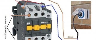
To connect the SIP wire and the AVVG cable, nut-type connectors could be used. But since the cable will pass through the house, to protect it, an automatic switch was installed, which made the connection between these conductors.
Automatic entry device
From the side of the dacha cooperative: the electrician climbed onto the pole and secured another anchor clamp to the metal clamp. Then in this clamp, using a wedge, he secured the SIP wire. And with the help of branch clamps with piercing the insulation of the SIP, we connected our wire to the main line
Installation of SIP on a pole
Branch piercing clamp for SIP
Cable fastening
To carry out the input of electricity from a pole with your own hands, you need to choose a method for attaching the cable to the wall of the building. This will be easy to do using ordinary fittings. Next, the cable is mounted to the outside of the wall in a manner appropriate to the material from which the building is constructed and the desired aesthetic result.
Buy power cable VVGnglsElectrical wiring diagram in the garage - features of design and installation with your own hands. 120 photos of wiring examples and video instructions for replacing wiring in the garage
Which wire to use for grounding: calculation of parameters, marking and purpose of various types of wires (video instructions + 150 photos)
The best and most reliable option is to run the wire through a corrugated or plastic cable channel. This will take a lot of time and effort, but you will be satisfied with the result.
Selection and calculation of the introductory machine
To protect the input cable, we need to select a circuit breaker for input into the house, which is selected according to the rated current flowing through it when consumers are turned on. In order to determine the rated current of the input circuit breaker, it is necessary to calculate the total power of all consumers in the house. We have compiled a table showing the name and power of the consumer
| electrical appliance | Power, W |
| LCD TV | 200 |
| Fridge | 600 |
| Boiler | 2000 |
| Iron | 1500 |
| Electric kettle | 1800 |
| Microwave | 1000 |
| Computer | 500 |
| Lighting | 800 |
| Well pump | 1000 |
| Air conditioner | 400 |
| Total | 9800 |
But since consumers cannot all be turned on at the same time, the demand coefficient is used for calculations, which is equal to 0.7 when the number of receivers in the room is from 5 to 200.
Using the formula, we determine the estimated total active power of consumers:
Calculation of active power of all consumers
Next, you need to calculate the total total power of consumers in the house using the following formula:
Calculation of the total power of all consumers
where cos phi is the power factor, for residential premises it lies in the range of 0.96 - 0.98.
Now we determine the calculated current for a single-phase network using the following formula
Rated current calculation
where Unom is the rated voltage of a single-phase network equal to 220 V
Now, based on the calculated current, we select the rating of the input circuit breaker. For internal power supply of apartments and houses, modular circuit breakers of standard ratings are used:
6, 10, 16, 25, 32, 40, 50, 63 A
The rated current of the machine must be equal to or the nearest greater from the standard range.
In our case, for an introductory machine, we need a machine with a rated current of 32 A
Working with wires
Ivanov Kostya
It is best to start rolling out the wires with the longest sections. Especially if the bays are small, 100 meters each. Otherwise, a piece of 10 meters will remain, but 12 meters will be needed. And leave short sections, for example, from the box to the outlet, for completion.
- I unwind the cable near the shield and pull it through the walls to the desired box.
- I pulled it to the box, but I don’t tuck it in right away, first I cut it up and remove the outer insulation (it’s easier for me than cutting it up inside the box).
- I remove about 15 cm of insulation - you can use your palm to guide you, you estimate it once, and then you don’t even need a tape measure.
- I insert it into the box so that the outer (black) insulation goes 1 cm into the box.
- I lay the cable, regardless of the method (strip, clamps, pipes), I drive the excess towards the shield.
The height of the shield was determined by the customer, 10 cm was added to this level (the level of the finished floor) and contours were drawn with a marker to cut the cable to the required length. The shield will be for 54 modules, leave 70 cm of cable below the lower border, on average leave a meter, since the shield can be for 108 modules. The length of the following cables will be identical. If the cables come from below, focus on the upper border.
To mark the ends - a wall tablet with paper sheets (color and written designation).
After the box is completely assembled, insulated and closed with a lid, it is advisable to protect the inlet channels from the ingress of mortar during the plastering process. You can use mineral wool and liquid solution.
Since the floors in the house are wooden, the cables to the lamps are laid in a metal profile pipe 15×15×1.5 mm (there was no round one on sale). I pre-painted the pipes, while marking and sanding, the paint dried even in the cold weather.
I fixed the pipes to pieces of plaster beacons - first I “baited them”, after laying the cable I fixed them tightly with self-tapping screws.
On concrete floors - in corrugation.
Ivanov Kostya
The corrugation limits the spread of smoke. A large volume of smoke in the limited space of the corrugation prevents the appearance of a flame. A flame will not appear under the plaster even without corrugation - there is no access to oxygen.
Selection and calculation of input cable
The aluminum cable AVVG 2x10 mm2 was mentioned above, perhaps you were wondering where the figure came from? Everything is very simple, before purchasing we made a preliminary calculation of this conductor.
The cross-section of the cable for entry into the house is calculated based on the maximum permissible current at which heating of the conductor will not cause damage to the insulation of the input cable.
Those. our cable must withstand the current for a long time at which the thermal release of the machine will operate.
The thermal release current is assumed to be 15-20% greater than the rated current of the machine and is calculated using the formula:
Calculation of thermal release current
Now from the PUE, in tables 1.3.4 for copper conductors and 1.3.5 for aluminum conductors, we select the required cross-section of the cable laid in one pipe from the “ one two-core ” column, equal to or the nearest larger.
Table 1.3.4. Permissible continuous current for wires and cords with rubber and polyvinyl chloride insulation with copper conductors
| Cross-section of current-carrying conductor, mm2 | Current, A, for wires laid | |||||
| open | in one pipe | |||||
| two single-core | three single-core | four single-core | one two-wire | one three-wire | ||
| 0,5 | 11 | — | — | — | — | — |
| 0.75 | 15 | — | — | — | — | — |
| 1 | 17 | 16 | 15 | 14 | 15 | 14 |
| 1,2 | 20 | 18 | 16 | 15 | 16 | 14,5 |
| 1,5 | 23 | 19 | 17 | 16 | 18 | 15 |
| 2 | 26 | 24 | 22 | 20 | 23 | 19 |
| 2,5 | 30 | 27 | 25 | 25 | 25 | 21 |
| 3 | 34 | 32 | 28 | 26 | 28 | 24 |
| 4 | 41 | 38 | 35 | 30 | 32 | 27 |
| 5 | 46 | 42 | 39 | 34 | 37 | 31 |
| 6 | 50 | 46 | 42 | 40 | 40 | 34 |
| 8 | 62 | 54 | 51 | 46 | 48 | 43 |
| 10 | 80 | 70 | 60 | 50 | 55 | 50 |
| 16 | 100 | 85 | 80 | 75 | 80 | 70 |
| 25 | 140 | 115 | 100 | 90 | 100 | 85 |
Table 1.3.5. Permissible continuous current for rubber and polyvinyl chloride insulated wires with aluminum conductors
| Cross-section of current-carrying conductor, mm2 | Current, A, for wires laid | |||||
| open | in one pipe | |||||
| two single-core | three single-core | Four single-core | one two-wire | one three-wire | ||
| 2 | 21 | 19 | 18 | 15 | 17 | 14 |
| 2,5 | 24 | 20 | 19 | 19 | 19 | 16 |
| 3 | 27 | 24 | 22 | 21 | 22 | 18 |
| 4 | 32 | 28 | 28 | 23 | 25 | 21 |
| 5 | 36 | 32 | 30 | 27 | 28 | 24 |
| 6 | 39 | 36 | 32 | 30 | 31 | 26 |
| 8 | 46 | 43 | 40 | 37 | 38 | 32 |
| 10 | 60 | 50 | 47 | 39 | 42 | 38 |
| 16 | 75 | 60 | 60 | 55 | 60 | 55 |
| 25 | 105 | 85 | 80 | 70 | 75 | 65 |
According to the tables, cable cross-sections are suitable for us: 6 mm2 for a copper conductor and 10 mm2 for an aluminum conductor.
Recommendations
According to the rules, you cannot insert a cable through a structure that could catch fire. Such materials include plastic, wood and other materials based on them.
- To make cable entry into the house safe, you need to switch to a conductor that does not burn. Copper is most often used.
- Wires in a special braid can be routed through walls made of wood and other flammable materials to the shield.
- It is recommended to initially make the hole for the wire wider in diameter than the wire itself.
- Then insulate the inside with non-flammable conductors. This will provide an additional level of security.
It is also worth considering that running a cable through, for example, a wooden wall is only possible if the cable is placed in a steel pipe. The thickness of the walls is strictly regulated; it should be approximately 4 times greater than the diameter of the wire itself.
Selecting a single-phase electric meter
When choosing an electricity meter, we were guided by the following criteria:
- single-phase;
- rated (maximum) current;
- fastening method;
- operating principle of the device.
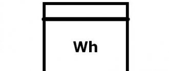
Since we live in a modern world, we therefore wanted to have a modern electricity meter with an electronic display. In the store we were offered a single-phase multi-tariff meter Energomera CE 102
Single-phase multi-tariff meter Energomera CE 102
It fully meets our selection criteria, here is a list of its characteristics:
- Accuracy class 1
- Number of tariffs 4
- Measuring network frequency, Hz 50±2.5
- Rated voltage, V 230
- Basic (maximum) current, A 5 (60); 10 (100)
- Starting current, mA 10; 20
- Parallel circuit power consumption, no more, V*A (W) 9 (0.8)
- Total power consumption of the series circuit, no more, V*A 0.1
- Operating temperature range, °C from minus 45 to plus 70
Connection diagram for Energomera CE 102 counter
Meter connection diagram
Grounding
Ivanov Kostya
With a CT grounding system, usually either a 2-wire cable or a 4-wire cable enters the house. And the grounding wire is inserted into the panel separately. Here I used a metal strip rather than a wire; I think it’s more reliable. I went to a metal depot, bought 30 meters of 25x4 mm strip and made this kind of grounding in the house. Or rather, not grounding, but SUP. The grounding itself on the street was done in the summer. Now I drilled the base and brought two pieces of wire d 6 mm out onto the street. At first I wanted one figure eight, but then I decided that two short pieces of 6 mm each would be easier to bend. I'll weld it on the street when I finish the shield. At home, these wires were immediately welded to the strip.
Branch into the kitchen - under the window there will be a sink and dishwasher.
Branch to the boiler room - branch to the panel and branch to the boiler, pumps and other equipment.
Advantages of SIP
A SIP type cable includes several cores, combined by twisting into a single structure. The entire surface of this bundle is covered with insulation, which is cross-linked or thermoplastic polyethylene.
The technical capabilities of SIPs allow us to achieve better technical performance in comparison with old type wires (A or AC). Legacy cables did not use an insulating layer, but rather each core was installed individually using dedicated insulators located on the crossarms. In SIP, the device is much simpler, since the harness pre-tensioned by a winch is simply fixed to the support.
SIPs can even be installed on walls, which was impossible with the old type of wires. This feature is especially important in urban conditions, since it becomes possible to use short supports and install cables near low-current lines.
SIP allows you to save material and technical resources. For example, such a cable does not require wide forest clearings for power lines, as is the case with old-style wires. In addition, SIPs are reliable: such wires are less susceptible to breaks and overlaps, and therefore to short circuits. And the SIP structure itself is stronger: breaking four tightly twisted wires is not easy.
SIP is resistant to moisture, low temperatures and temperature changes. If an ice crust inevitably forms on ordinary wiring in winter (resulting in broken lines), then the SIP wires are protected by an insulating layer that prevents icing of the material.
The only exception to the above is the two-core modification SIP-1, in which the load-bearing conductor is not covered with insulation. In other cables, the supporting conductors are either inside the bundle (SIP-4) or insulated.
It should be said that SIP has become a technical standard: all energy sales organizations require the use of this particular type of cable to organize new connections.
One of the motivations of marketers: SIP allows you to avoid unauthorized connections (in other words, theft of electricity), which is easy to organize in the case of uninsulated wiring.
In addition, thanks to special devices, it is possible to arrange branches from the main cable without turning off the power. This possibility is provided by the presence of an insulating layer. Consequently, another advantage of SIP is operational safety.
And, finally, another advantage of SIP is the smallest losses among competitors when transporting energy over long distances. This is achieved by low reactance (for old type cables this figure is three times higher).
Differential machines
In practice, instead of residual current devices, differential circuit breakers are often used.
These are devices that combine RCD and AV in one housing. It makes sense to use automatic devices if this device will protect a separate line or an individual consumer. If you protect several lines with a difautomatic device, then each will need to additionally install its own AB (unless, of course, the selectivity of the system is important to you, and you do not want to violate it).
Cross module
In modern power supply systems, several groups of electrical consumers are often used (socket group, lighting, etc.). And in order to distribute the electricity supplied to the panel from the input cable between different groups, it is recommended to install a modular distribution block (cross-module) on the DIN rail. The cross-module allows you to insert one conductor into the panel, designed for a large load, and receive at the output several lines of a smaller cross-section (which depends on the load on a particular group of consumers).
In addition, installing a cross-module ensures reliable electrical connections and simplifies the process of connecting additional devices to an existing electrical panel.
Organization of the entry point
During the connection process, a cable line (underground or overhead) is drawn from the street electricity metering panel (MU), located on the power transmission line tap-off support, to the distribution panel (DP), mounted indoors.
The metering panel (MCB) often contains only an input machine and an electricity meter. Circuit breakers, residual current devices and other elements, which will be discussed below, are installed in the distribution panel (DP), which is installed directly in the house.
In some cases, equipment for the control room and control panel can be installed in the same building.
The operating parameters of the equipment installed in the metering panel, its list and quantity - all this must be specified in the power supply project (or at least must be calculated by specialized specialists). But there are requirements that apply directly to the design of the electrical panel.
Sergey Savelyev Head of Technical Department of Legrand Group in Russia
The design of the electrical panel must ensure convenient supply of the power cable; it must contain neutral buses and grounding buses. At the same time, the electrical panel must have internal space sufficient to accommodate numerous outgoing cables, and its reserve necessary for possible expansion and modernization of the electrical installation.
We add that the body of the shield must be resistant to fire or made of self-extinguishing material. At the same time, he is obliged to reliably protect the built-in equipment from possible damage. A lock built into the door or dashboard handle will help prevent intentional damage, and protection from dust and moisture is guaranteed by the IP protection degree specified in the specification. If the shield is intended to be installed outdoors or indoors, where increased protection from moisture, dust and mechanical damage is required, then it is better to give preference to shields of class IP65 – IK09.
In order to avoid disagreements during the connection process with specialists from energy supply companies (whose requirements often contradict each other), a power supply project should be developed and agreed upon simultaneously with the architectural design.
If the connection point is organized in accordance with the requirements of the agreed electrical project, the owner of the site, as a rule, does not have problems during the connection process and further checks by regulatory organizations. Consequently, the work associated with installing and completing the electrical panel will not be in vain.
Let's talk about what the configuration of a home switchboard should be.
Selection of section and grade
When choosing a brand of SIP, you should take into account the following factors:
- purpose of the overhead line;
- operating conditions, installation location, safety requirements;
- the required number of phases;
- total estimated power.
Design features of different brands of SIP:
- SIP-1: bare steel core on a zero load-bearing core;
- SIP-2: the zero of the load-bearing core is covered with insulating material;
- SIP-3: each core has a reinforced core enclosed in an insulating layer;
- SIP-4: the cores are insulated, but the cores are not used;
- SIP-5: there are no cores, and light-stabilized polyethylene is used as insulation. The cable is marked “NG”, which indicates its non-flammability. SIP-5 can be used even inside buildings, although to a greater extent this SIP, like any other, is intended for external lines.
The easiest way is to select the SIP section. The fact is that the minimum cross-section of such a cable cannot be less than 16 square millimeters. This is more than enough to provide electricity to an average-sized private home.
If you need to insert a cable into a large private house or apartment building, you will have to use special reference tables to calculate the required cross-section.
The most common SIP is two-wire (zero and phase) or four-wire (two additional phases). Cables with five cores and an additional PE protective conductor are very rarely used.
Rules for connecting electricity to the house
Requirements for connecting electricity to a private home
The incoming power supply device is subject to the requirements of the PUE and technical specifications. They indicate:
- location of connection points - 25 m from the border with neighbors;
- the cable distance from power line supports to the wall is 10 cm if the house is wooden and 5 cm from brick surfaces;
- cable thickness for a single-phase line – 0.6 cm for copper conductors, 1.6 cm for aluminum conductors;
- the need to seal the inlet groove with non-combustible material;
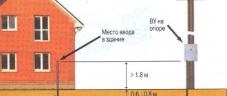
- the location of the inlet is 2.75 m from the ground line and 1.5 m from the window;
- compliance of the equipment power with the allocated power of 15 kW;
- The straight line distance from the power grid to which the site is adjacent is 300 m for the city and 500 m for the village.
Mandatory elements of the system are SIP wires, an electric meter, a switchboard, and an intermediate metal support.
Correct connection options
Electricity can be supplied to a private home in two ways:
- Airborne is an inexpensive but noticeable option. The main part of the cable is stretched outdoors above the ground. The conductor can pass into the room in a pipe through the wall to switchgear or meters. It is allowed to connect outside the home to a voltage stabilizer or metering device;
- Underground - a hidden method, when the wire is laid in an asbestos-cement pipe buried in the ground. The entrance to the building is through a technological hole in the foundation. From the power line to the entry point, the cable is laid along the pole.
For underground installations, use heavy-duty wires.
Sequence of connecting RCDs and circuit breakers
The first connection rule: if a phase is taken from one RCD, then zero from all consumers connected to this phase must return to the original RCD. That is, the neutral and phase wires should not be mixed with other neutrals and phases after the RCD.
In the diagram we see two circuit breakers going to the lighting groups (protection of lighting lines using an RCD is not mandatory). The fire protection RCD is not indicated in this diagram. The socket groups are protected by a protective shutdown with a rating of 40 A and 30 mA.
Connection is simple:
- the lighting groups are not connected to the RCD, so the neutral and phase wires are branched off to them after the input circuit breaker;
- the phase for the socket groups is taken from one RCD;
- The zero of the socket group is connected to a separate zero busbar, which is also connected to the RCD.
When completing electrical panels, you should avoid situations in which an unlimited number of lines are connected to one RCD. To ensure this condition, the standard panel is equipped with several residual current devices. In this case, RCDs are grouped by type of connected premises and by type of load. For example, the socket group of the bathroom is connected to an RCD with a nominal value of 10 mA, and the socket groups of the kitchen and living quarters are connected to an RCD with a nominal value of 30 mA.