Criteria for selecting a well pump
When choosing this device, you should consider the following:
- Operating point of the unit This indicator determines the intersection of the device parameters with the properties of the well. It is known that water in wells does not have a constant level. These indicators are indicated in the passport of the water source. If there is no such document, you can take measurements yourself. It is recommended to take several measurements to obtain an average water level. It is important that their average indicator coincides with the passport characteristics of the purchased equipment, which operates in the range from 70 to 120% of its nominal parameters.
- Types of well pumps Knowing the depth of the water source, you can determine what type of unit is needed - surface or submersible.
Fundamental differences between pump types:
- A self-priming surface device will allow you to raise water from a depth of up to 9 m. This option is suitable for small wells. Its advantage is the possibility of external fastening and easy accessibility in case of need for repair or dismantling. The negative thing is that this unit freezes in the cold and requires filling the suction channel with water before starting work. These devices are divided into: - centrifugal without an ejector, - self-priming with an ejector.
- The submersible unit will allow you to work at any depth. This type is the most suitable in any situation. It is more difficult to install, but such a pump works all year round.
Read more about choosing a well pump based on key technical characteristics and installation conditions.
WINTER OPTION WITH INSTALLATION OF METAL CAISSON
A caisson is an underground metal structure (chamber) located directly above the well, welded hermetically to the casing, and performs several functions:
- Protects the wellhead from flooding and pollution by flood waters.
- Protects the system from freezing and makes it possible to operate the well all year round, and not just in the warm season.
- Makes it possible to place equipment (battery tank, control unit and cable and pipe distribution) directly above the well, in the absence of a special room in the house.
- Provides convenient access to equipment for inspection, repair or maintenance.
| When constructing a turnkey well, the caisson neck cover is at least 5 centimeters above the ground. | When constructing a well in winter, the caisson neck is additionally insulated. | When constructing a turnkey well, all water-lifting equipment is installed in the caisson. |
Length of water pipeline and number of nodes
Although water will move horizontally through the system, losses in nodes and pipes cannot be avoided. It is recommended to purchase purchased equipment with a power reserve of up to 20%.
These devices are also divided into two categories:
- centrifugal , which have a higher price and better performance;
- vibration ones , which cost less and work worse.
Vibration pumps have a suction valve, which can be located:
- at the top of the device;
- at the bottom of the device.
The ability to avoid the ingress of bottom dirt, in the first option, can be compensated by the problem of working with a low water level in the well.
The second option has downsides - such a pump sucks up clay near the bottom, while the low water level will become much less of an obstacle.
The installation of vibration devices is not recommended in sand wells, which are generally considered to be all channels drilled to the depth of interstratal or groundwater.
Possible errors when connecting equipment
Types of check valves
Pump failure cannot be avoided if the height of its suspension is incorrectly determined. If set too low, small pebbles or sand will get into the pump. If, on the contrary, it is too high, air may be sucked in. Neglecting to install a non-return valve has a negative impact on the pressure device. In such a situation, each time it starts, it first fills a vertical pipe with water, and after shutting down, it is affected by a water hammer.
As the height of the water rises, the impact force increases, so the damage done to the pump will be greater.
It is also not recommended that the cross-section of the water supply pipe be too small. The operating period will remain unchanged, but this will have a bad effect on performance. Uninstalled electrical protection, especially in areas with voltage surges, can cause pump failure.
It is better to connect electrical devices through stabilizers, and complex and expensive electrical equipment through special control and protection stations. The cross-section of the electrical wire must be sufficient, otherwise the operating time of the motor will be significantly reduced.
If automation and instrumentation are installed incorrectly, as well as when pressure equipment is connected to the well, an accident in the system is inevitable. If you know little about the topic, it is better to entrust the work to professionals.
Well pump kit
Submersible pumps for meeting domestic needs are designed to work in wells Ø 75-100 mm. Models are distinguished by power, pressure, performance and type of drive (single-phase, three-phase).
The standard configuration of pumping equipment is as follows: a pump plus a power cable.
This arrangement may be sufficient if the device is intended to be used at the dacha for watering the garden.
To organize water supply at home, the devices are equipped with a control panel and additional equipment:
- automation unit;
- pressure gauge;
- pressure switch;
- hydraulic accumulator;
- check and drain valves;
- filter elements;
- deep-well pump protection unit;
- electrical voltage stabilizer.
The control package consists of a relay and a set of sensors that monitor the state of the installation and allow it to operate autonomously without human intervention.
The membrane accumulator is designed to equalize the pressure of the water supply system.
A protection sensor and voltage stabilizer support the operation of the mechanism during emergency situations, including:
- low water level in the well;
- phase failure;
- power surges;
- short circuit;
- pump overload or underload;
- engine overheating.
How to Determine the Required Source Depth
The borehole pump must be installed at a certain depth of the water source. When using a well as a source of water supply, the static and dynamic levels of the location of the pumped liquid medium in it are taken into account. The static level is understood as the distance at which the surface of water, in a calm state, is located from the surface of the earth. At the dynamic level, water is in the well after it begins to be pumped out.
Dynamics of a water column in a well
In order for submersible pumping equipment to function effectively and be cooled efficiently by the liquid medium it pumps, it should be located in the well at a level at least 30 cm below the dynamic level. If the thickness of the water layer allows, then it will be better if the deep pump is installed at a level located 2–3 m below the dynamic level. It should be taken into account that the pump installed in the well should be located at a distance of at least 1–2 m from its bottom.
Main functions of automation units for pumps
A large number of suburban areas are equipped with wells and boreholes. The owners strive to have an autonomous source of water. More often this is a technical resource that is used for irrigation. But such water is also used quite actively as drinking water. In terms of chemical composition, it can significantly exceed tap water, especially if the intake is carried out from a great depth.
The automation operation scheme for water supply pumps and wells is not inferior in efficiency to central systems.
In order for the process to be technically optimal and meet the requirements, many people prefer to buy automation for a well pump.
Based on functionality, mechanisms can be divided into two types:
- automatic control of water supply;
- protective system.
Regulating mechanisms allow you to adjust the required flow. When watering - more intense, for domestic needs, including for supply to heating and household appliances - less force.
A protective mechanism prevents damage to the unit in the event of a significant voltage drop. In situations where the water level has changed, pumping is impossible; when turned on, dry running occurs.
A well-established scheme for the operation of a well and automation for water supply pumps is not inferior to central systems in terms of operating efficiency and even in some respects surpasses them. When using an individual source, interruptions and shutdowns are eliminated; electricity costs are less than paying for the amount of water consumed from the central water supply system. In cases where it is possible to use it as drinking water, the advantage becomes even more significant.
Based on functionality, automation is divided into regulating water supply and protective.
Recommendations for pump placement and positioning
When calculating to what depth to immerse the pump in the well and the location of the pump in the well, it is useful to follow the following recommendations:
- The electric pump should not come into contact with the walls of the column, so it is hung strictly in the center of the head.
- When the electric pump is lowered into a well in sand below the dynamic level, it is better to make the distance from the surface of the water a little more than recommended, for example, 5 meters. This will help to avoid the unpleasant consequences of a situation when, during operation, the source silts up, its flow rate and, accordingly, the dynamic threshold decreases. In order to lower the electric pump deeper in the future, you will have to lengthen or change the water pipe and cable cut to fit the head - this will lead to unjustified financial expenses.
- If, according to the parameters of the well, the electric pump must be located in the bottom area, it is better to use screw types - they cope better with pumping contaminated water, and replacing their simple parts is cheaper.
Rice. 9 Lowering the pump into the well
When placing an electric pump in a well, it is advisable to use such characteristics as dynamic and static level. Lowering the pumping equipment slightly below the dynamic mark contributes to less load on the body and working mechanism of the unit, the intake of cleaner water from the source, saves materials and simplifies maintenance.
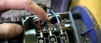
Connecting a well pump without auxiliary equipment
The method of connecting the device without additional equipment allows its short-term operation under strict user control. This connection diagram for a well pump explains the very principle of starting the unit and cannot serve as a standard for permanent use.
Sequencing:
- Before assembling the structure, it is necessary to check the operation of the electric motor. To do this, connect it to the network for 10 seconds and make sure there are no extraneous sounds.
- Equip the bottom of the casing with a coarse filter.
- Using a steel cable, attach the mechanism to the head flange through the eyes in the housing.
- Install a check valve on the suction pipeline at a distance of 1-7 m from the pump.
- Connect the power cable.
- Carefully, without jerking, lower the device into the well until it touches the ground. Then smoothly lift it to a height of 1 m from the bottom of the excavation and fix it.
- Plug the device into a power outlet connected to the house grounding bus.
Connection procedure: step-by-step instructions
Pumping stations are suitable for equipping relatively deep water intake workings. If the depth of the groundwater table exceeds the maximum value specified by the equipment manufacturer, remote ejectors are used.
To install, perform the following steps:
- A trench is laid connecting the well and housing.
- Pipes are laid in it.
- Install a water supply system (if it is missing).
- Install the unit in the selected location.
- The supply pipe is equipped with a filter and a check valve.
- Connect the line to the receiving pipe.
- Connect the unit to the water supply.
- Connect the equipment to the power supply.
- Fill the hydraulic tank with water.
- Perform a test run of the station.
- Check the joints.
- Set up the pressure switch.
The pipes of the external pipeline of the water supply system must be laid below the level to which the ground freezes. It is recommended to make a slight slope from the house to the well so that the water returns to the pump if it stops working. This will protect the device from overheating and damage due to dry running, i.e. work in the absence of water.
The same protective function is performed by a check valve, which does not allow liquid to leave the pipe and go into the well. When connecting a surface pump equipped with an ejector, it is necessary to connect another one to the suction pipe, which is connected to the ejector.
This unit directs part of the incoming liquid to the base of the pipe through which the liquid flows, which significantly increases the productivity of the equipment. If a submersible pump is used, the work is performed differently. It is connected to the suction pipe and suspended on a durable stainless steel cable.
The lower end of the supply pipe should be equipped with a strainer to prevent sand and other impurities from contaminating the water and damaging the equipment.
Submersible pumps are conveniently attached to a finished head. Such a device is mounted on the top of the casing pipe. It is believed that sealing a well with a cap allows it to slightly increase its flow rate. To prevent the cable and cable from getting tangled, they are fixed to the pipe using plastic ties.
If the filter is already in the pump, you are limited to installing a check valve. The edge of the surface pump supply line should be located at a height of more than a meter. This minimum distance is half a meter for a submersible pump.
Connections between the unit and pipes must be made using American taps; valves are used to shut off any section and disconnect it for repairs without damaging the remaining elements of the system.
It is recommended to install an additional coarse filter in front of the station, and after it, install a filter that will ensure the purity of drinking water by removing unwanted impurities
The well filter installed in the excavation wears out over time, and sand begins to seep through it. It is recommended to install an additional coarse filter at the pump inlet.
Power supply is provided by connecting a separate line to the equipment, equipped with an automatic shutdown device; care must be taken to ground it. Before starting, the device is filled with water through the hole provided for this purpose.
There should be pressure in the hydraulic tank:
- about 1.5 bar for containers less than 30 l;
- about 1.8 bar for 30-50 l;
- 2 bar or a little less for a 50-100 l tank.
Then the hole for filling the water is closed and the device is connected to the electrical network. You need to open the valve slightly to bleed the air. In a few minutes, water will flow from here. Otherwise, turn off the device and add a little more liquid.
To adjust the pressure switch, it is necessary to remove the housing from it in order to gain access to the screws with which the device is adjusted
Turn on again so that the device starts working normally. Now you need to configure the relay. To do this, the HA will have to be emptied and then filled again. Indicators are set by rotating the corresponding screws.
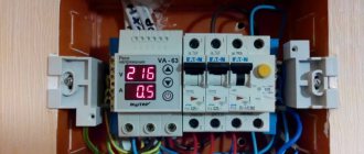
Connecting the well pump to the power supply with the control unit of the automation unit
Diagram of connecting a well pump to the power supply with a control unit (automation).
The control unit is designed to control the operation of submersible pumps without user intervention. The completeness of the cabinet varies depending on the chosen model and the manufacturer.
The standard set consists of the following elements:
- contactor with thermal regulator;
- indicator lamps;
- dry running relay;
- voltage level control unit;
- starting protective device “soft start”;
- power circuit breaker;
- terminals for connecting sensors and a submersible pump to automation;
- two-position automatic machine;
- cable entries.
Based on the list of equipment, we can conclude that the installation of the cabinet must be entrusted to specialists who will connect all the sensors and adjust the operation of the pumping equipment.
Relay selection
When choosing a hydraulic relay, you are guided by its range in the water supply; the standard value is 1.5 - 3 bar. When connecting using a pressure gauge, adjust it using the adjusting screws. Do the same with the dry-running relay, setting it to turn off the power when the pressure in the line is less than 1.5 bar. If a private house has a high number of floors, then to supply water with the required pressure to the upper floors, the relay is additionally adjusted, increasing the upper and lower response thresholds.
For example, if the height of the rise to the upper floors is 5 meters (1 bar corresponds to 10 meters of vertical water column), then 0.5 bar is added to the upper and lower response limits and the resulting response range is from 2 to 3.5 bar . The brand chosen for water supply at home must have the appropriate pressure range according to the passport.
Rice. 8 Pumping units with floats and electrolytic sensors
Automation: main components and their purpose
Before connecting a submersible pump for a well or well, a water main with the necessary automation is installed. Automatic control systems are the same for any type of electric pump, the only difference is in the settings of the control devices and the volume of the hydraulic accumulator. There are only a few main nodes; when connected, they are placed in one place and perform the following functions.
We recommend: Heating a country house: a review of options for solving the heating problem
Pressure switch
The main device that automatically controls the operation of the electric pump. Externally, the device looks like a small box with a fitting for connecting to a water line. The principle of operation of the pressure switch is quite simple: if the pressure in the system exceeds the permissible value, water presses on the valve located inside the housing behind the fitting, and a metal plate with a pusher connected to the valve diaphragm opens the contacts inside the device.
During operation, the power cable of the electric pump passes through the pressure switch, at the same time the supply circuit is broken and the pumping equipment is turned off. It is possible to adjust the pressure switch in a certain range using two adjusting screws - one sets the upper response threshold, the second screw regulates the difference between the pressure that starts and turns off the device.
Rice. 2 Automation for deep-well pump
Hydraulic accumulator and the advantages of its use
When the electric pump is turned on and off, the water in the water supply system suddenly stops or immediately begins to move - this causes water hammer, during which the pipeline and equipment experience increased loads.
When consuming water, if there is not a certain reserve, the pump will turn on and off at short intervals - this will lead to increased loads on the system and equipment and will accelerate wear on the electric pump.
To eliminate the above negative factors, a hydraulic accumulator is installed in the water supply system. The device is a cylindrical metal tank, inside of which there is a rubber membrane. With the taps closed, the rubber flask of the tank is filled with water, and the pressure in the accumulator should be equal to or slightly lower than the pressure in the system. When using water, it enters the pipes from the battery, increasing the time the electric pump is turned off.
It is clear that the larger the volume of the hydraulic tank per pump, the greater the supply of water in the system and the longer the time the equipment will be at rest between start and stop, therefore, its service life will increase.
Any membrane tank has a nipple in the wall for pumping and releasing air into the chamber - this allows you to equalize the pressure in the system and the air gap behind the rubber bulb of the accumulator. If there was no such pressure in the accumulator, the rubber membrane would spread along the walls of the tank from the pressure of water and would not be able to perform its functions.
The standard minimum value of the hydraulic tank volume is not less than 10 liters, the upper limit can reach up to 100 liters.
Advice from experienced specialists
It is recommended to connect the accumulator pressure switch to the electrical panel of the house via a separate line with its own RCD.
It is also imperative to ground this sensor; for this there are special terminals on it.
It is permissible to tighten the adjusting nuts on the relay as far as possible, but it is not recommended at all. A device with tightly tightened springs will work with large errors in the set Start and Stop, and will soon fail
If water is visible on the body or inside the relay, the device should be immediately disconnected from power. The appearance of moisture is a direct sign of a rupture of the rubber membrane. Such a unit must be immediately replaced; it cannot be repaired or continued to be used.
Cleaning filters must be installed in the system. It’s impossible without them. However, they need to be cleaned regularly.
Also, once every quarter or six months the pressure switch itself should be washed. To do this, unscrew the lid on the device with the inlet pipe at the bottom. Next, the opened cavity and the membrane located there are washed.
The main reason for breakdowns of the hydraulic accumulator relay is the appearance of air, sand or other contaminants in the pipes. The rubber membrane ruptures, and as a result the device must be replaced
The pressure switch should be checked for correct operation and general serviceability once every 3–6 months. At the same time, the air pressure in the accumulator is also checked.
If, during adjustment, sharp jumps in the needle on the pressure gauge occur, then this is a direct sign of a breakdown of the relay, pump or hydraulic accumulator. It is necessary to turn off the entire system and begin a full check of it.
Features of equipment installation
There are two options for installing the pump:
- The self-priming device is mounted next to the water source. A special submersible hose is lowered into the water at one end and attached to the pump at the other.
- The submersible device is attached to the pipe. If it is a flexible hose, then an addition to the fasteners can be a cable, which is attached with one end to the pump, and the other to any stable element with a well. A flexible installation option is preferable, as it allows you to adjust the immersion depth of the unit. The pump is completely immersed in water. Most of these devices do not tolerate dry operation well. Therefore, it is always worth monitoring the level in the well or purchasing a pump with a float switch that will protect the device in the event of no or critically low water levels.
It is recommended to install a check valve on the pipe itself, which will keep water in the system.
The algorithm for installing submersible equipment includes the following points:
- All pipes are installed. If the pump will be installed on a rigid pipe, then it is recommended to place a small piece of flexible hose between it and the main channel for moving water into the house, which will dampen engine vibrations.
- The following are connected to the device: - cable, - electrical wire, - hose.
- The pump smoothly lowers to the bottom of the well.
- When the unit touches the bottom, the entire structure should be raised to a height of half a meter to a meter from the point of contact.
- The cable must be firmly secured, the wire must be connected to the network, the hose must be connected to the rest of the system and placed in the fastening channels.
- It is recommended to provide the upper hole of the well with a cover to prevent foreign objects and dirt from entering the system.
The electrical connection should only be made to a grounded source using a circuit breaker according to the following diagram:
Electrical connection diagram for a well pump
When installing the pump, you may need metal fluoroplastovie bushings; their options can be viewed here https://cema-bearing.com/metalloforoplastovie_vtulki/.
Installation of a submersible electric pump for installation in a well
To install a submersible electric pump in a well, work is performed in the following order:
- Screws a plastic adapter coupling into the outlet of the unit to connect the pressure pipeline. If there is no built-in check valve, install your own, mounting it first at the outlet of the electric pump, then screw on the fitting for connecting HDPE pipes.
- They attach a pipe to the pump and fix it with a plastic cuff, thread a cable through the ears of the housing and connect its ends at the outlet using two special clamps, the free end is screwed to the main cable with electrical tape.
- Connect the power cable, cable and pressure hose together using electrical tape or zip ties in 1 meter increments, making sure that the power cord is secured without tension.
- The electric pump is lowered into the well to a predetermined depth. To do this, measure and cut the pressure pipe to the required length, insert it into the head, to which the cable is tied.
- After a dive, you can immediately check the operation of the electric pump without connecting to the pipeline, if the liquid supply corresponds to the passport data, connect the entire water line and then monitor and regulate the operation of the equipment with automatic devices.
Rice. 8 Preparing the downhole electric pump for immersion
To connect a well pump to a water supply system, devices are used that automate its operation, prevent frequent startup and reduce the load on the line. They can be independently assembled in one module, installed in a living space, or left in a caisson pit with a borehole head.
Well features
When the well is completely ready for operation, you can turn on the pump and start pumping water out of it, the quality and quantity of which can vary greatly. The main influence on this is exerted by several indicators, namely: 1. Depth
Water with different properties is extracted from different depths. These depths of occurrence of natural resources are usually called horizons. In cases with water wells, four such horizons are distinguished:
- A simple well with a depth of up to 20 meters.
- Well-well , having a parameter of up to 30 m.
- Sandy horizon , which is located at a distance of 50 - 70 m below the ground surface level.
- Artesian horizon . Its depth can be 100 meters and below.
We recommend: How to make a chimney for a potbelly stove: installing a proper chimney with your own hands
The choice of the depth of the future water source will depend on many factors, some of which are:
- purpose of the source,
- required amount of water,
- presence or absence of permits,
- price,
- geodetic conditions of the area,
- depth of the aquifer.
2. Diameter
This indicator directly depends on:
- parameters of drilling equipment,
- characteristics of the future pump,
- affordability of the process,
- intended purpose.
The larger the diameter, the more expensive the well will cost, the larger the diameter of the pipes required for its installation.
The positive side will be high productivity. When choosing a drilling diameter, you should always be guided by the principle of sufficient necessity. At the same time, it is recommended to make a small margin in the parameters, since it is not always known for certain:
- how much water the future source will provide;
- how quickly it will recover;
- how the well will behave after a long time.
3. Well flow rate
This definition refers to the maximum amount of water that can be pumped out of a well in one hour. This parameter not only depends on the power of the installed equipment, but also on the recovery ability of the source itself. It is rare that large volumes of water can be endlessly pumped out of a well or a drilled artesian canal. The more powerful the equipment, the sooner the water will be pumped out. The more often pumping is done, the smaller the volumes will be. Weak equipment can work for a long time, pumping up to the top as much water as is restored in the well. Determining the exact flow rate is a complex process and unnecessary for individual use sources.
4. Volume of water consumed
This indicator depends on the flow rate of the source and the needs of its user. If water consumption is less than the well can provide, then problems with water shortage can be avoided.
The amount of water in the well, in addition to its depth and width, may depend on:
- season,
- pumping intensity,
- parameters of the equipment used.
Correct calculation of consumption will allow rational use of valuable natural resources. This will additionally allow you to:
- save energy,
- extend the life of the pump,
- provide higher quality and cleaner produced water.
A competent and careful approach to the arrangement of an autonomous source of water supply for a site will give its owner the opportunity to access the most valuable natural resource, which must be treated with respect and love. This will definitely have positive consequences in the near and distant future.
Installing a pump in a well
An important point when carrying out water supply work for a country house is the proper installation of the pump in the well. If the equipment is installed correctly, this is a guarantee of its long and uninterrupted operation.
Despite the fact that there is nothing complicated in installing a pump in a well, there are also some nuances that should be taken into account before starting work.
Important criteria when selecting water supply equipment
If the water supply equipment was selected incorrectly, installing a well pump can be a rather difficult task. The parameters that must be taken into account when choosing pumping equipment include the following:
- Dynamic and static level of a water artesian well. You can find this information in the installation passport. If you do not have such data, for example, due to the loss of documents, do not panic - this information is restored experimentally;
- To calculate the required volume of water that must be provided by the installed equipment, count the number of water consumption points. These include a sink, bathtub, shower, toilet, washing machine, dishwasher, etc.;
- Distance between the house and the water trunk.
What are the dangers of unqualified installation of a pump in a well?
If errors were made during the installation of downhole equipment or low-quality materials were used, this can cause a number of negative consequences. There are often cases when work performed by non-professionals leads to breaks in water-lifting products, the impossibility of dismantling when replacement is necessary, as well as premature breakdowns of pumps.
The first two scenarios, when the old equipment cannot be removed from the well, jeopardize the possibility of its subsequent use. Because of this, all the work has to be done anew: they drill another well, install a new caisson, since using the old one is impractical, and install new equipment.
Scheme for a submersible well pump
To connect the pump to a well in the country, first select a water intake: an open natural reservoir, a well, or drill a water well. In this case, the depth of the horizontal liquid is taken into account. Up to 8 m - the hydraulic unit is fixed superficially, deeper - it is lowered into the drilled hole. Taking into account the depth of immersion and the diameter of the drill, a cylindrical apparatus of smaller diameter is used.
Before immersing the hydraulic mechanism, lower the measuring cord with a load to the bottom, find out at what depth the liquid is located. Using a measuring cord, the exact footage of the descent and the length of the horizontal water layer are determined. If it is at a depth of 60 m, they drill further.
Connecting a submersible pump with your own hands consists of 3 stages:
- Select according to the technical characteristics of the pump model.
- Attaching a cable with an automation electrical cable and a lifting pipe.
- Fastening the head to the hydraulic apparatus body.
Preference is given to screw and centrifugal designs, their advantages:
- low cost, resistance to pressure;
- connection of additional pumps;
- synchronous operation with automation;
- productivity – high efficiency with the required pressure.
The manufacturer provides a deep well pump with a table and graphs that show the ratio of pressure and displacement of liquid at the outlet. If it rises from a depth of 80 m, according to the table, the water supply network receives 30 liters. When pumping, the passage of water along a horizontal plume is taken into account: 5 m of horizon corresponds to 1 m of pressure height.
To immerse the water apparatus and hold it in the well, a steel cable is used, which is passed through the 2 upper holes of the housing head. Secure with plastic clamps parallel to the electrical cable and water-lifting polypropylene pipe. The pipe is connected at the bottom with a collapsible brass or plastic coupling.
WINTER OPTION WITH INSTALLATION OF WELL ADAPTER
The cost of installing a water well according to the “winter option” can be reduced by refusing to install a caisson, “replacing” it with a well adapter, which is installed on the casing and allows you to bring the water pipe below the freezing level.
However, the downhole adapter has many disadvantages (complexity of installation on a two-pipe well, difficulties with lifting a pump located at a depth of 60 m, extreme difficulty in installing a pumping unit at a depth of over 60 m, etc.).
Another inconvenience is the need to place a hydraulic storage tank and automatic control in the house. Having weighed all the pros and cons, the conclusion does not allow us to talk about the advantage of the downhole adapter (except for the price) over the caisson.
| The downhole adapter is installed at a depth of 1.8 meters, and the well cover covers the casing. | To construct a well without a caisson, a well adapter and a well cap are used. | To set up a turnkey well, you need a high-quality well adapter and cap. |
Scheme for a surface well pump
Conditions allow the pump to be installed upstairs. Then a scheme is used for a surface well pump, which is recommended to be placed next to the source. The advantage of an outdoor location is that the device is easily accessible if repairs need to be made.
Operation of a surface hydraulic unit is not complicated. Install a pump to the water well, lower the hose into the tank, turn on the start-up protection unit, and press the “Start” button. Recommended location for efficient work and safety:
- a few meters, closer to the water intake;
- as far as possible from the populated area;
- indoors, with exhaust ventilation;
- on a solid foundation.
When connecting a surface water unit, use:
- fitting for connections;
- hose, water intake hose;
- pipe entering the storage tank;
- a set of irrigation hoses;
- fittings, fasteners, clamps.
SUMMER OPTION FOR WATERING AN AREA WITH INSTALLATION OF A WELL CAP
If you are going to use the well exclusively for summer irrigation, then the option for its arrangement will be the least labor-intensive and, accordingly, the cheapest.
After all, you only need to install a pump with a water-lifting pipe and a well head.
If desired, you can install compact automation that allows you to control the well pump depending on the water intake, without using bulky hydraulic storage tanks.
| Summer arrangement of a well for irrigation. | Summer construction of a water well. | Summer well construction. |
| Summer well construction without a caisson. | Summer well construction price. | Summer well construction on a turnkey basis. |
Types of protective automation for well pumps, connecting blocks
When choosing an automation unit for a well pump, you should pay attention to the voltage indicator recommended for normal operation of the latter, and to the permissible deviations. To protect the device from running without water, it is necessary to install a U-shaped relay. This element will turn off the pump if no water flows into it.
Modern manufacturers offer several types of protective mechanisms to ensure safe operation of pumps:
- Start-protective, they are based on printed circuit boards;
- relay blocks;
- devices whose operation is provided by microprocessors.
The connection diagram of a well pump to an automatic system that prevents overheating is carried out by performing the following steps:
Modern protective mechanisms are starter-protective, relay and microprocessor-based.
1. You need to prepare the equipment. Need to purchase:
- hydraulic tank (hydraulic accumulator);
- pressure gauge;
- adapter coupling with collet clamp;
- plastic pipes and brass adapter.
2. Wrap the entrance to the hydraulic accumulator with fum tape and screw on the adapter coupling.
3. Connect a pressure gauge and relay to the brass adapter.
4. Connect the brass adapter and the adapter coupling.
5. From a plastic pipe, assemble an elbow that will connect the relay and battery with the water supply system.
6. Connect the well pump hose using a coupling with a collet clamp.
Note! After assembling the system, be sure to ensure that the cable is securely fastened to the terminal block.
Connection diagram for pressure switch RD5 and protection LP/3
You can simplify the circuit, otherwise reduce its cost, without losing installation quality, by installing an LP/3 protection relay instead of the automation unit. The main disadvantage of this scheme is the need to manually start the pump after shutdown, which is compensated by its low cost.
Pay special attention to connecting RD5 and LP/3 in a single circuit. They are connected in series, that is, when the pressure drops and when running dry (lack of water), the pump turns off. Again, in this scheme the pump is restarted manually.
Control automation for a submersible pump
The automation system that regulates the operation of the pump consists of several elements. The main one is the control relay, which is supplemented by the electrical part. Depending on the features of the configuration, there are two principles of operation of the devices.
The control automation for a submersible pump consists of a control relay and an electrical part.
Regulation of water pressure in the pipeline. Valid when water is supplied from a well and the system has a hydraulic tank. After the first rise, it fills the container and is then fed into the home system. Automation operating according to this scheme has a sensor with electrodes.
Some units (usually intended for wells) are equipped with special floats to control the amount of water. It should be noted that the price of submersible pumps for wells with automation of this type is quite high, but the devices are in demand. Regardless of the method of controlling the filling of the accumulator, all tanks have an emergency drain, which, if necessary, will reduce the pressure in the tank. A positive characteristic of the operation of just such a control system is the stable operation of the pump, ensured by constant hydraulics.
Level control. This is done using commands. A certain pressure is set on the relay, the pump turns on and off depending on its change. A similar scheme is actively used in private areas; it also requires the presence of a membrane tank. As positive characteristics of such a scheme, it should be noted the relative ease of installation and the low price of the automation. The ideal picture is slightly spoiled by the inaccuracy of readings and the short service life in a system with vibration pumps.
Note! When using a pressure level control circuit, the relay can be installed in the power circuit of the pump. The pressure switch can be installed in the power circuit of the pump.
Kinds
All automation used to control the operation of the pump is divided into 3 types in chronological order according to the sequence of its creation.
1st generation
This is the first and simplest automated control system for pumping equipment. It is used for simple tasks when you need to provide a constant source of water in the house. It consists of three main parts.
- Dry running sensor.
It is necessary to turn off the pump in the absence of water, which serves as a coolant; without it, the pump will overheat and the winding will burn out. But an additional float switch can also be installed. Its function is similar to a sensor and is based on the water level: when it drops, the pump turns off. These simple mechanisms reliably protect expensive equipment from damage. - Hydraulic accumulator.
It is a necessary element for system automation. Performs the function of a water reservoir, inside of which there is a membrane. - Relay
. The device that controls the pressure level must be equipped with a pressure gauge that allows you to adjust the operating parameters of the relay contacts.
Dry running sensor
Hydraulic accumulator
Pressure switch
The first generation automation for deep well pumps is simple due to the absence of complex electrical circuits, and therefore its installation on any pumping equipment is not a problem.
The functionality of the system is as simple as the operating mechanism, which is based on reducing the pressure in the accumulator when water is consumed. As a result, the pump turns on and fills the container with new liquid. When completely filled, the pump turns off. This process continues cyclically
. It is possible to adjust the minimum and maximum pressure using a relay. The pressure gauge allows you to set the lower and upper limits of automatic operation.
2nd generation
The second generation differs from the first in the use of an electronic control unit to which sensors are connected. They are distributed throughout the pumping system and monitor the operation of the pump itself and the condition of the pipeline. All information goes to the electronic unit, which processes it and makes appropriate decisions.
When using 2nd generation automation, a hydraulic accumulator may not be used, since the pipeline and the sensor installed in it perform a similar function. When the pressure in the pipe drops, a signal from the sensor enters the control unit, which, in turn, turns on the pump and restores the water pressure to the previous level, and upon completion turns it off.
To install 2nd generation automation, basic skills in handling electronics are required.
The principle of operation of the 1st and 2nd generation systems is similar - pressure control, but the cost of the 2nd generation system is much more expensive, as a result of which it is in less demand.
3rd generation
This system is highly reliable and efficient, but is also more expensive than its predecessors. Precise operation of the system is ensured by advanced electronics and allows you to save on electricity. To connect this system, you need a specialist who will not only install, but also configure the correct operation of the unit. Automation provides a full range of equipment protection against breakdowns, from “dry running” and pipeline rupture to protection against power surges in the network. The principle of operation, as in the 2nd generation, is not associated with the use of a hydraulic accumulator.
The main difference is the ability to more accurately regulate the operation of mechanical components.
For example, when turned on, the pump usually pumps water at maximum power, which is not necessary when its consumption is low, and electricity is consumed to the maximum.
How to make a water pump with your own hands at home
Summer residents are not lazy and savvy people. Therefore, the question of how to make a water pump with your own hands without electricity is asked quite often. In fact, there are many options, all of them are quite feasible. One of the most effective and most affordable is a pump based on a pump mechanism. This is the type that is most often used in conditions where there is no electricity.
We recommend: Designer batteries, types, photos, operating features, technical specifications
To create a pump you will need the following elements and parts:
- PVC pipe with a diameter of 5 cm;
- PPR pipe with a diameter of 2.4 cm;
- two 0.5 inch check valves;
- pipe plugs and bends;
- 8 mm bolts with nuts, rubber gaskets.
The pump is assembled from the above parts. The main thing is to ensure the tightness of the structure, otherwise the mechanism will not work. The piston creates pressure in the working chamber. Under its influence, water, passing through the valves, is supplied to the outlet. It is very important that the gaskets fit tightly.
It is difficult to perceive when described, but in fact it does not cause problems to create a pump powered by solar energy with your own hands. The operating principle is somewhat reminiscent of how a submersible pump is connected to a hydraulic accumulator: gas takes part in pushing out water.
A pump based on a pump mechanism is the most affordable to make yourself.
Required components:
- metal grate;
- rubber bulb;
- cylinder with propane-butane mixture.
The grate is filled with gas and connected to the bulb. The pear is placed in a tank pre-equipped with valves for inlet and outlet. Solar energy expands the gas, the latter pushes out air, providing a pressure difference in the water tank.
Note! All tank seams must be sealed tightly. Such a pump must be located in a well-lit place.
Some important recommendations
A special brass fitting is used to connect the check valve to the water supply pipe. The connection must also have a special drive sleeve. This measure will prevent the pipe from shrinking in diameter and will compensate for the excess stress created by the compression fitting.
The fitting, like all connecting elements, must be of high quality, designed for increased tensile loads. Otherwise, the pipe may simply jump out of the fitting. To connect the opposite end of the HDPE pipe with the outlet at the head, use the same compression drive-in fitting made of brass.
A special electrical cable for submersible pumps is available for sale. It is this that must be used to connect to the pump. Substitutions with lower quality materials are not acceptable.
The power cable is connected to the pump cable by soldering; it is better not to use twisting in such an important place. The connection point is covered with a heat-shrink sleeve
To secure the cable and cable to the water supply pipe, you need plastic clamps. They are installed every 2-3 meters. This measure helps to avoid accidental tangling of the cable while lowering the structure down. Instead of clamps, you can use electrical tape.
To attach the cable and cable to the water supply pipe, you can use plastic clamps. A special adapter will allow you to reliably connect the pump to the pipe
For the sake of economy, a special cable is used only in the area where it will be immersed in water. The remaining distance is covered by a regular PVS cable.
In any case, the cable cross-section must comply with the manufacturer’s recommendations specified in the pump data sheet.
Soldering is performed at the junction of the power cable and the pump cable. After this, the cable is closed with a special heat-shrink sleeve. To install it you will need a hair dryer
The pump can only be suspended from a stainless steel cable. Neither regular black steel nor its galvanized version are designed to withstand continuous use in water.
When lowering the pump in narrow areas, you can supplement the rotation of the pump with a small amount of pressure. But in any case, the pump must maintain a vertical position.
During installation of the pump, the well head may move slightly. You should make sure that the weight of the pump rests on the cable and is not supported by the pipe. Only after this the position of the head can be fixed with screws.
Reasons for decreasing pressure in the system and how to increase water pressure in the pumping station
Situations when the water pressure in a pumping station does not meet the requirements are quite common. Do not rush to adjust the operation of the automatic water pump. To solve problems, you should first carry out the following diagnostics:
Water pressure is affected not only by automation, but also by the condition of the filters, air pressure in the system, and the tightness of the suction pipeline.
- Check the condition of the filters. Impurities of sand, clay and other elements can not only clog filters, but also cause corrosion of system elements, which will certainly affect the efficiency of the pump.
- Measure the air pressure in the system. Its reduction also affects the full functioning of the station.
- Make sure the suction pipe is tight.
If, as a result of the above actions, no problems are identified, it is necessary to intervene in the operation of the automation: check the condition of the hydraulic accumulator and set the pressure switch for the well pump. Quite often a mistake is made in which a high level of lower pressure is set. The station practically does not turn off in this mode, which, naturally, has a detrimental effect on its functioning.
Low pressure can also be caused by damage to the membrane or microcracks in the tank. Sometimes it is impossible to eliminate defects; a complete replacement of the hydraulic accumulator is required.
The water pressure in the system is easily regulated automatically.
An example of a pumping station with a “Malysh” pump.
For an automatic pumping station you will need (minimum equipment):
— pump Baby 750 rub.
— 3/4″ inch reinforced hose, for pressure up to 6-8 atm (for connecting a pump in a well with a hydraulic accumulator in the house and further to the point of water collection)
— coarse filter 50 rub.
- hydraulic accumulator, capacity min. 20 l - about 1000 rubles.
— 3/4 inch check valve (placed in front of the hydraulic accumulator) 100 RUR.
- 6 atm pressure gauge. 160 rub.
— pressure switch model RDM 5 price approx. 500 rub.
— a fitting with 5 nipples (five-piece) for connecting the entire equipment to each other.
— clamps for securing hoses, sealing gaskets, flax for sealing threads.
The water supply system is installed as follows. A hydraulic tank with an automation system is installed in a barn or in a house and is connected to a pump in the well with a hose and electrical wiring. Water is supplied to consumers from the hydraulic tank through a pipe. And now more details. We assemble the automation unit: we connect two electrical wires with plugs to the pressure switch, screw a filter, a pressure gauge, a pressure switch onto the five-piece, and screw the entire structure into the hydraulic accumulator. We connect a check valve to the filter with the flow direction towards the hydraulic tank.
We connect the “Baby” pump with a flexible hose to a check valve. From the five-piece on the hydraulic accumulator we lead a pipe or hose to the consumer. Everything is done with hydraulics, now electrics. We install two sockets for the pump control system - one in the well and connect the pump plug to it, the second in the barn or in the house where the hydraulic accumulator with automatic equipment is located and connect the pressure relay output voltage plug to it. We install another socket next to the hydraulic accumulator, connect 220 V to it, lower the pump into the well and plug in the second plug of the pressure switch into the network. ALL. The water supply for the dacha is ready! The pump works and supplies water to the tank with an automatic system. As soon as the pressure in the tank reaches the set value, the relay will operate and turn off the pump. The maximum and minimum pressure in the system is regulated by a pressure switch.
Well pump with automation: operating features, connection
Is there a difference between borehole and sump pumps? Yes, but it would be more accurate to say that pumps with certain technical characteristics are used to pump water out of a well. These are monoblock centrifugal devices, where the engine, water intake elements and pipe are located in one housing.
The well pump is installed at a depth of no more than 25 m. It has a rather low performance. The pump for an automatic well should be positioned so that it does not drift along the water layer. It is also necessary to eliminate vibrations of the unit, as they will raise all sorts of unwanted particles from the bottom.
It should be noted that the protection against solid particles entering and sticking to the wheel blades in well pumps is weak. Therefore, when pumping contaminated water, they quickly lose their rated performance.
Well pumps, that is, centrifugal ones, differ from vibration pumps in the way they are protected from running dry. It consists of the following: when the intensity of the water flow entering the pump decreases (when air enters), the current strength of the device’s electric motor also decreases. The sensor reacts to the current situation by giving a signal to turn off the unit.
Connecting a submersible pump for a well is carried out according to the same scheme as for a well pump.
The connection diagram for a submersible pump for a well is almost the same as for a well pump. The only difference is in the method of fixation: the borehole is attached to the head; for a well, a metal frame is made, a hole is made in it, into which the cable is inserted.
Most popular
Dry running is the operation of the engine without or without sufficient water.
Typically, modern units are already equipped with protection against overheating and dry running. A distinctive feature of this scheme is the use of current of different frequencies for the smoothest possible acceleration and stopping of the pump motor.
Models with three wires support the ability to turn on the pick-up point in the extreme upper and extreme lower positions. It contains a certain volume of water, sufficient for a small flow rate. Using a drainer, it is convenient to water plants in garden plots directly, or by filling large containers for further drip irrigation. The main difference is the ability to more accurately regulate the operation of mechanical components. Such automation did not have electrical operating elements, so it worked very reliably, but only in water that was relatively clear of sand and suspended matter. For normal operation of electric motors, fuses, thermal and magnetic circuit breakers, overload relays, etc. are used.
And not only the pump, but the entire system as a whole. It is enough to apply power, and the blades will immediately begin to capture water, supplying it to the system. The operating scheme is as follows: under the influence of current, a coil is magnetized, attracting the armature. Water is pushed into the discharge chamber.
Further activation of the device occurs when the pressure changes - the valve opens and closes. When using a powerful pump with a pressure of more than 10 bar, a pressure reducer should be installed in front of the automation unit. In the drainage connection diagram, a valve and a check valve are additionally installed in the pressure pipeline to prevent the reverse outflow of liquid. Indeed, during operation, these devices reliably protect all components and parts of an autonomous water supply station from premature wear and failure. The units have long proven themselves to be high-performance, long service life and high-quality workmanship.
The device is responsible for stable pressure in the supply line and starts and turns off the pump if necessary. Therefore, an important step is the correct installation and configuration of all components. It turns on the system when the pressure decreases, the valve opens, and turns it off when the flow stops, the valve closes. But since the unit is installed near a well, a PVC water intake pipe with a diameter of 25-35 mm is connected to its input.
Sensors monitor the fluid level in the accumulator. The connection is made according to a scheme similar to the previous one. When water flow begins, the pressure in the accumulator decreases. Installing a Gilex “water cannon” pump on a well
How to raise water to a height without a pump: video, description
Do not rush to assess the conditions for cultivating soil without electricity as extreme. It is in such situations that a considerable number of gardeners find themselves who have developed plots of land in vacant lots and other unclaimed areas. Ingenuity and useful experience, which many share on the Internet, make it possible to organize water supply without electricity.
There are quite a few such pumping methods. The most accessible ones include the following:
An Archimedes screw is a device consisting of a cylinder and a screw placed inside it with a handle for rotation.
- Application of the Archimedes screw. The device consists of a hollow cylinder and a screw placed inside it with a handle for rotation. The system must be lowered into the source at an angle. A mechanically driven screw takes in water and delivers it upward.
- Using a hydraulic ram. The method was invented by the Montgolfier mechanic. It is based on the kinetic energy of water: the flow passing through a rigid pipe is blocked, and water flows through a check valve into the hydraulic tank located above. The tank is equipped with a fitting at the bottom, onto which a hose is placed that supplies water to the consumer.
To get more information on how to raise water to a height without a pump, it is worth watching the video:
On a note! When creating a mechanical water supply device, it should be taken into account that the most effective and affordable method is a piston system.
The best pump manufacturers
Before purchasing this device, you need to study the list of proven manufacturing brands.
These include:
- Russian manufacturer Unipamp.
- Danish manufacturer Grundfos.
- German manufacturer Vilo Nova.
- Italian manufacturer of DAB.
How to lay a pipeline
To ensure unhindered flow of water from the well, a water supply system is laid (see Water supply in a private house from a well: connection features). Usually it is buried in the ground to a depth below the level where the soil begins to freeze. Otherwise, you need to insulate the main line.
The work is performed in this order:
- A trench is dug with a slight slope towards the well.
- At the optimal height, a hole is made in the foundation for the pipe.
- The pipe is being laid.
- The pipeline is connected to pumping equipment.
From the outside:
- A metal mesh is attached, which will also serve as a coarse filter.
- A check valve is installed to ensure stable filling of the pipe with water.
Single- and double-pipe pumps – which one to choose?
Installation and connection of a household pumping station is carried out only in cases where a well is drilled in a country house with a depth of no more than 20 m. If the aquifers lie lower in the ground, there will be no use from a compact pump. In such situations, a special deep-well pump should be installed.
When selecting the equipment we are interested in, we should pay attention to its technical parameters and operating modes, and not just the cost of the pumping station. First of all, you need to decide on the type of suction pipeline. Pumping station
Pumping station
It happens:
- ejector (in other words, two-pipe);
- single-pipe.
Single pipe stations are very simple in design. In them, fluid from the well enters the housing of the pumping equipment used through the only available line. Installing such a unit yourself can be done without problems, and quite quickly. Pumps with two pipes are a structurally more complex device. But the efficiency of its operation is many times higher and more reliable than single-pipe equipment.
In an ejector pumping station, the rise of water is ensured by vacuum, which is formed by a special wheel. It is initially installed in the unit. The increase in vacuum is due to the inertia of the liquid, which makes a circular motion when the equipment is turned on. Due to this scheme, pumps with two pipes are always characterized by low power, while having a high efficiency. They are capable of lifting liquid from great depths. Therefore, installing a two-pipe pumping station is recommended for depths of 10–20 m. If the well depth is less than 10 m, feel free to install equipment with one line. It will cope with its tasks one hundred percent.
How to connect a circulation pump to electricity – Construction and repair
The circulation pump is an important element of modern heating systems. It is needed for forced circulation of water in the heating system, which allows you to save up to 30% on heating private houses and cottages.
The savings lie in the fact that the coolant quickly passes through the pipes, as a result of which the water does not cool down so quickly and, accordingly, there is no need to heat it very much. This article will discuss the correct connection of the circulation pump to the electrical network.
Diagrams and video instructions will help you carry out electrical installation yourself without errors!
Connection methods
Electrical connection using a plug and socket. This method involves installing an electrical outlet in close proximity to the place where the circulation pump is mounted. Sometimes they can be supplied with a connected cable and plug included, as in the photo:
In this case, you can simply plug the device into the mains using an outlet located within reach of the cable. You just need to make sure there is a third, grounding contact in the outlet.
If there is no cord with a plug, they need to be purchased or removed from an unused electrical appliance.
You should pay attention to the cross-section of the cord conductors. It should be between 1.5 mm 2 and 2.5 mm 2
The wires must be stranded copper, ensuring resistance to repeated bending. The cord with a plug for connecting electrical appliances to the network is shown in the photo below:
Before connecting the circulation pump, you need to find out which of the three wires of the cord is connected to the ground pin of the plug. This can be done using an ohmmeter, while at the same time checking the integrity of the remaining wires.
We unscrew the clamp of the cable coupling (in the first photo it is a plastic nut into which the cable is inserted), put it on our cord, and insert the cord into the coupling. If there is a cable tie inside the box, thread the cord through it. We connect the ends of the cord wires, previously stripped of insulation, to the terminals.
The wires connected to the plugs of the plug should be connected to the L and N terminals (don’t be afraid to mix them up, this is not critical), the wire of the grounding contact of the plug should be connected to the PE terminal (but you can’t make a mistake here).
The instructions supplied with the product prohibit its operation without protective grounding. Next, tighten the clamp (if any), tighten the cable sleeve clamp tightly, and close the terminal box cover.
The pump is ready to be plugged into the mains.
Fixed connection. The connection diagram for the circulation pump to the electrical network with grounding is provided below:
The requirements for the wire cross-section here are the same as in the previous version. For this installation, the cable can be used either flexible or inflexible, copper, VVG brand. or aluminum, AVVG. If the cable is inflexible, the installation should ensure that it does not move. To do this, the cable along the entire route is secured with clamps.
In this embodiment, a residual current device (differential circuit breaker) is used. Instead, you can use a regular single-pole circuit breaker, passing only the phase wire through it.
If the machine is installed in a panel where there is a PE bus, then the cable from the pump to the machine must be three-core. If there is no such bus, the PE terminal should be connected to a grounding device.
This connection can be made with a separate wire.
Separately, I would like to consider such an installation option as connecting the pump to the UPS. It is the most preferable and ensures the independence of the heating system from power outages. The connection diagram of the circulation pump to the uninterruptible power supply is provided below:
The power of the UPS should be selected based on the power of the pump motor.
The capacity of the battery is determined by the estimated time of autonomous power supply of the circulation pump, that is, the time when the power supply is turned off.
Finally, we recommend watching video instructions for connecting various pump models to the electrical network:
Connection diagram of the circulation pump to the thermostat
So we looked at how to properly connect the circulation pump to the electrical network. The diagram and video examples helped to consolidate the material and clearly see the nuances of installation!
It will be useful to read:
Connection diagram of the circulation pump to the thermostat
Where to install the pump - supply or return
Despite the abundance of information on the Internet, it is quite difficult for the user to understand how to correctly install a heating pump in order to ensure forced circulation of water in the system of their own home. The reason is the inconsistency of this information, which causes constant debate on thematic forums. Most of the so-called specialists claim that the unit is installed only on the return pipeline, citing the following conclusions:
- the coolant temperature in the supply is much higher than in the return, so the pump will not last long;
- The density of hot water in the supply line is less, so it is more difficult to pump;
- The static pressure in the return line is higher, which makes the pump easier to operate.
We respond to the above statements point by point:
- Household circulation pumps are designed for a maximum coolant temperature of 110 °C. In a home heating network it rarely rises above 70 degrees, and the boiler will not heat the water more than 90 °C.
- The density of water at 50 degrees is 988 kg/m³, and at 70 °C – 977.8 kg/m³. For a unit that develops a pressure of 4-6 m of water column and is capable of pumping about a ton of coolant in 1 hour, the difference in the density of the transported medium is 10 kg/m³ (the volume of a ten-liter canister) is simply negligible.
- In practice, the difference in static pressure of the coolant in the supply and return lines is equally insignificant.
Hence the simple conclusion: circulation pumps for heating can be installed both in the return and supply pipelines of the heating system of a private house. This factor will not in any way affect the performance of the unit or the heating efficiency of the building.
Boiler room made by our expert Vladimir Sukhorukov. There is convenient access to all equipment, including pumps.
The exception is cheap solid fuel direct combustion boilers that are not equipped with automation. When overheated, the coolant in them boils, since burning wood cannot be extinguished at once. If the circulation pump is installed on the supply side, then the resulting steam mixed with water enters the housing with the impeller. The further process looks like this:
- The impeller of the pumping device is not designed to move gases. Therefore, the performance of the device decreases sharply, and the flow rate of the coolant drops.
- Less cooling water enters the boiler tank, causing overheating to increase and even more steam to be produced.
- An increase in the amount of steam and its entry into the impeller leads to a complete stop of the coolant movement in the system. An emergency situation occurs and, as a result of an increase in pressure, a safety valve is activated, releasing steam directly into the boiler room.
- If no measures are taken to extinguish the firewood, the valve cannot cope with the pressure release and an explosion occurs with the destruction of the boiler shell.
Practice shows that no more than 5 minutes pass from the start of the overheating process to the valve activation. If you install a circulation pump on the return pipe, then steam will not enter it and the time period before an accident will increase to 20 minutes. That is, installing the unit on the return line will not prevent an explosion, but will delay it, which will give more time to fix the problem. Hence the recommendation: it is better to install pumps for boilers running on wood and coal on the return pipeline.
For well-automated pellet heaters, the installation location does not matter. You will learn more information on the topic from our expert’s video:
What should a good pump be like?
First you need to select and purchase a suitable pump, as well as a number of materials necessary for its successful installation. The pump is usually submersible, but it is highly desirable that it be centrifugal.
Unlike centrifugal models, vibrating pumps cause dangerous vibrations in the well, which can lead to destruction of the soil and casing. Such models are especially dangerous for sand wells, which are less stable than their artesian counterparts.
The pump power must correspond to the productivity of the well. In addition, the immersion depth for which a particular pump is designed should be taken into account. A model designed to operate at a depth of 50 m can supply water from a depth of 60 m, but the pump will soon break down.
A submersible centrifugal pump is the optimal choice for a well. Its performance, size and other indicators should be correlated with the characteristics of your own water source
Another risk factor is the level of quality of drilling work. If an experienced team drilled, the well will better withstand the destructive effects. And for wells created with your own hands or through the efforts of “shabashniks”, it is recommended to use not just a centrifugal pump, but special models for wells.
Such devices better withstand the loads associated with pumping water heavily contaminated with sand, silt, clay particles, etc. Another important point is the diameter of the pump. It must match the dimensions of the casing pipe
It is also important to take into account the power supply features of the pump. Both single-phase and three-phase devices are used for wells
It is easier to find equipment for four-inch pipes than for three-inch pipes. It would be good if this point was taken into account at the well planning stage. The greater the distance from the pipe walls to the pump housing, the better. If the pump fits into the pipe with difficulty rather than freely, you need to look for a model with a smaller diameter.
Care and maintenance
Inexpensive ovens do not have a self-cleaning system or a special protective coating. Such models will have to be cleaned manually using cleaning products. The main thing is to use gentle sprays, powders, gels
It is important to remember that pre-soaked stains are easiest to remove.
Cleaning the oven will be faster if all dirt is pre-soaked.
Mid-price slabs are covered with enamel, which can be easily cleaned with a damp cloth. To remove dried dirt, you will need to use mild cleaning agents.
Expensive models are equipped with a self-cleaning system, without requiring any mechanical action to remove contaminants. Simply wipe the surface with a damp cloth.
Expensive models of ovens are equipped with a self-cleaning system that is very convenient for housewives.
Methods for automating water wells
The simplest and most inexpensive way to automate wells is to install them on a mechanical pressure regulator. If the pressure created by the water is too low, the contacts of the pumping equipment are closed, and then it is turned on. After turning off the water supply, the tap must be closed and the pressure level increased.
The installation of a pressure switch equipped with a pressure gauge is carried out at any point in the pumping system, the disadvantage of which is the lack of protection against “dry running”. The pressure switch supplies electricity to the equipment if the pressure begins to drop. The pump will continue to operate until the entire system fails. Its operation must be regulated, so a hydraulic accumulator is built into the system, performing the following functions:
- preventing frequent pump starts;
- absorbing water shocks that occur in the event of a sudden closure of the tap.
A hydraulic accumulator is a tank made from ferrous metal or stainless steel. The device can be painted blue. The capacity of the device is 5-500 l. The number of starts of the pumping system depends on the volume of the tank.
Installing an automation unit for a well is another way to control the operation of the pump. These systems are advanced, so their cost is 10-15 times higher than the price of a simple relay. The automation system must include the following elements:
- LCD display;
- dry running protection;
- pump jam protection;
- automatic start;
- hydraulic accumulator
The most expensive type of automation for well pumps is considered a frequency converter. It provides the frequency required to maintain pressure in the pumping system. It becomes operational only after opening the 2nd tap and increasing the water flow.
When using frequency converters, the minimum motor speed is used. It is 20-30% of the nominal value, which is indicated in the technical documentation for the device. If the requirement is not met, the device may fail.
General information
Previously, all houses installed a system through which the working environment moved naturally. The movement of water was ensured by heating it in a boiler or even an ordinary furnace. It cooled in the radiators and other elements of the building’s thermal circuit, after which it was returned to the heating equipment. It was according to this simple scheme that it circulated through the pipes.
Nowadays additional equipment is used everywhere. Before installing a pump in a heating system in a private home, specialists perform calculations and select a device, taking into account the characteristics of the building’s thermal circuit. Professionals also take other nuances into account.
On a note! A thermal circuit with natural circulation is just a relatively simple heating circuit. After all, when installing it, pipes must be laid with a slope, batteries are mounted in strictly specified places, and pipelines of exceptionally large diameter are used. In some buildings, all the rules are difficult or impossible to comply with. Therefore, it is not possible to ensure the required coolant circulation through the system.
Conventional diagram of the thermal circuit of a building with natural movement of coolant Source rtkpipe.ru
Professional installation of additional equipment allows you to solve these problems. Most homeowners turn to specialists for help. After all, they know very well how to properly install a circulation pump in a heating system.
Electrical connection methods
There may be several connection options. Below are the most popular methods.
With the arrangement of a coffer chamber
The arrangement of the caisson chamber is carried out upon completion of construction work on the well.
The placement and connection of equipment is carried out according to the following scheme:
Symbols on the diagram:
A – caisson chamber; B – stable water level; C – rope for insurance; D – pump; E – dry running sensor, indispensable during the setup process; F – casing pipe installed in the well; G – electrical cable from the control panel; N – control panel; I – pressure switch; J – fitting with five inputs; L – additional drain valve; M – hydraulic accumulator; P – well filter at the outlet of the system: Q – check valve.
Connection with hydraulic accumulator
The presented circuit provides protection against water freezing. The filter is located in the middle part of the highway.
Symbols on the diagram:
1 – well head; 2 – electrical wire; 3 – pipe with galvanized surface; 4 – rope for insurance; 5 – sealed cable coupling, 6 – adapter; 7 – pipe; 8 – cable fixation; 9 – check valve; 10 – nipple; 11 – deep pump; 12 – frost protection; 13 – shut-off valve: 14 – tee; 15 – filter on the supply line; 16 – adapter; 17 – electronic unit; 18 – wiring hose; 19 – hydraulic accumulator.
In schemes without the use of automation, a direct connection to the electrical network is used. You just need to connect each group of contacts “phase”, “zero” and “ground”.
For a pumping installation using automation of various types and complexity, switching is performed according to a special scheme.
The advanced layout, which improves the quality of system operation, contains the following elements:
- Intermediate type switches or relays
- Pressure and level sensors
- Electric starters
- Hydraulic accumulator
Adding the listed devices to the pumping equipment lines makes the operation of the well pump fully automatic.
The main link of the electrical circuit is the starter. The normally open contact group is connected at the input to the power supply conductors of the network, and at the output it is connected to the pump power terminals. Starting and stopping the engine is controlled by a pressure switch.
To implement such an electrical circuit, a hydraulic accumulator with an installed check valve is required. A pressure relay sensor is built into the hydraulic accumulator, which ensures the operation of the contactor by turning on and off the supply voltage.
Pump automation
Control and monitoring of all devices installed in the system is provided by the automation unit. It is entrusted with the task of turning the electric motor on and off, protecting against “dry start” of the pump, and preventing emergency situations in power supply circuits.
The automatic block contains:
- Devices for protecting electric motor windings from overheating and phase imbalance in the network.
- A pressure switch that regulates the moment when the pressure in the network decreases to the maximum minimum and turns on the motor, followed by turning it off when the operating value is reached.
- Protection against starting the engine when there is no water in the pump.
Pump automation is divided into three types:
- Universal
- For installation in systems with hydraulic accumulator
- For systems without it
Depending on the complexity and functionality, three generations of automation systems are installed:
- Mechanical control is simple, reliable and accessible.
- Electromechanical systems of the second generation are characterized by perfect control and protection of the main components. Received the greatest distribution.
- Electronic system including digital instruments, microchips and pulse motor control of the pump. Installed for models of submersible pumps with frequency control.