I had already created several static electricity generators before and these projects always aroused great interest. They are a lot of fun to play with and allow you to do a lot of different tricks with ESD. For example, you can shock your friends (and yourself), force sand or dust particles with your hands to behave strangely, since they are susceptible to static charges. You can also attract a stream of water, charge paper so that it sticks to the wall, and perform many other magical tricks.
The video above demonstrates the assembly process for this project, and the text version below will give you step-by-step instructions. This is the third version of my static electricity generator, and it is the cheapest. It allows you to create a charge about the same as what happens when you catch a spark from a carpet while walking on it in your pajamas.
The USB ionizer, which is the main component of the project, can be found here: link
We will need:
- Ionizer.
- Insulated wire.
- Heat-shrink tubing.
- Hot glue.
- Solder and soldering iron.
- Button batteries 1.5v.
- Insulating tape.
Do-it-yourself Testatika electrostatic generator
Now there is quite a lot of information in the public domain about the appearance and operation of the device, all of it is speculative and technically complex. Over the years, the unit was demonstrated to various technicians and engineers who were invited into the community, but after 30 years, no one had ever produced a working prototype of the device so that it could be assembled outside of Methernitha. According to the Meternites, in order to understand nature and feel its voice, a person must experience silence and loneliness. After all, it was there that knowledge about this technology was obtained.
But craftsmen do not give up hope of getting free energy and are trying to recreate the creation of Paul Baumann with their own hands.
Source
What physical phenomena are used to neutralize static charges in everyday life and industry?
As we can see from the examples above, to eliminate static, the principle of deliberately connecting opposite potentials is used. This issue can be resolved in only two ways:
- connecting problem areas to a prepared conductive circuit;
- or humidification of dry air up to 50%.
In the first case, it is necessary to create in advance a system that ensures potential equalization and constantly use it.
The second method is often implemented by spraying special compounds with conductive properties into the air. The industry produces them in cans, which are commonly called antistatic spray.
It covers the treated surface with a thin layer and evens out static charges on it.
Antistatic spray works well with clothing, car interior trim and other household materials.
In production, special devices are used that produce anions and cations, which are directed to the surface being treated. They, interacting with oppositely charged ions on it, eliminate static charges.
This is how they work with:
- labels;
- big bag type packaging (soft container made of polypropylene fabric);
- shrink films;
- feed units for sheet or roll materials;
- textiles;
- packaging products;
- material cutting equipment;
- screen printing.
Serial neutralizers can be produced in the form of:
- antistatic fan blowing rolled or sheet products;
- an antistatic gun used by the operator to clean irregularly shaped objects or hard-to-reach places;
- point modules for working in confined spaces.
On an industrial scale, static electricity neutralization devices are used to remove the effects of electrification of products and equipment.
They are produced by manufacturers of complex pneumatic equipment. The operating principle is based on the creation of an ionized air flow, which is formed by a corona discharge smoldering at the tip of the electrode needle.
It acts as a precision electrostatic filter with a smart function. For this purpose, the sign of the generated ions is determined automatically by the device’s sensors, which allows high-quality discharges of accumulated static.
A pneumatic type neutralizer works more efficiently than conventional models that do not use a jet of compressed air.
Directed streams of ionized and blown air effectively treat surfaces, and the tip of the needle with a corona discharge always remains clean.
Materials and components
You will need for installation: a soldering iron and solder, a screwdriver and pliers. Two motors from old CD players and all sorts of small fastenings.
The generator runs on two AA batteries and is capable of creating discharges 2 cm long. The most difficult thing here is the 120 mm discs. They need to be made according to this principle: take two laser discs from a CD or DVD. Glue the segments with aluminum tape (25 sectors). Glue the discs to the motors. Make brushes from aluminum strips.
If everything is done and configured as necessary, the spark will reach a size of about 20 mm, and the discharge will strike every 0.5 seconds.
CLICK HERE AND OPEN COMMENTS
In order to then start the generator with the resulting static, at least by 10 watts, this static power will not be enough. And in order to have a hundred-watt generator at the static output as a load, the diameter of the static disks must be more than one meter. In addition, to coordinate kilowatt generators with disk statics, the generators must have exclusively non-standard technology. I would take the path of USING ready-made industry-standard generators from IM.
Another thing; Taking Preferred, with the purpose of using it in technology; At the same time, also try to understand what is written under the quality diagram: https://uploads.ru/MmRfO.jpg and try to adapt this to what is shown here, to INDUCTION, Motors, rotors, turbines, windmills, VD, BTG, self-propelled wheels, pendulums, Tesla car, then it will also be clear that 400 years ago there was a SELF-PROPELLED cart by Leonardo Da Vinci. ... - More information about using CE can be continued by voice on Skype: FILL1133
Both the mounting plates and disks have a lightning symbol - high voltage, and markings for the conductors of an electrophore machine, which means they are manufactured specifically for this purpose in an industrial way. Total: we bought an electrophore machine, disassembled it, reassembled it, and proudly told how easy it is to assemble an electrophore machine from old CDs. For once, try not to be a jerk, but actually make something from scrap materials.
What are the advantages of products manufactured using a static neutralizer?
Timely elimination of static charges allows you to:
- significantly reduce the number of manufacturing defects in relatively simple ways;
- create safe working conditions for operators involved in the maintenance and management of machines;
- optimize the production process, improve the quality of products;
- choose the most suitable equipment to eliminate the formation of static discharges.
Marat Fakhurdinov in his video explains in detail what a static electricity neutralizer is and on what principles it works.
And now I just remind you that it is convenient for you not only to ask a question, but also to express your own opinion about the material you read. Use the comments section.
Selecting ESD Protection
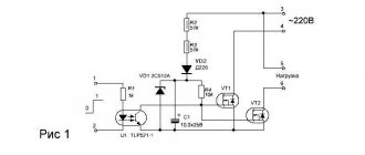
When designing a device's electrostatic protection, there are a number of key parameters to consider, as shown in Figure 6.
Rice. 6. Key parameters of anti-static electricity
To ensure the required rated voltage, transient voltage protection is required. Schemes of operation of the device with and without protection are shown in Figure 7.
Rice. 7. Transient voltage protection
Let's say the electrical signal changes according to the law shown as the blue curve in Figure 7. If there is no protection in the system, then such a signal will lead to system failure, since at some time the input voltage will exceed the breakdown voltage. If the system has protection (limiting diode), then when a certain voltage level is reached, the diode begins to conduct current, which limits further increase in voltage, as can be seen in Figure 7 (red curve). At times when the input voltage exceeds the diode response threshold, the current through the diode increases (black curve in Figure 7).
It should be noted that the protection circuit shown in Figure 7 limits positive voltage and completely filters out negative voltage, that is, it is unipolar. To pass a signal of both polarities, it is necessary to use a bipolar protection circuit, in which two diodes are connected back to back. Bipolar protection circuitry is required for audio and RF signals.
ESD protection should protect microcircuits without disrupting their normal operation. For example, the parasitic capacitance of ESD protection must be low enough to pass the entire spectrum of the desired signal without distortion.
A convenient tool for analyzing the quality of a data transmission channel is the eye diagram. It allows you to visualize the process of transmitting a sequence of data bits and show potential channel problems. To construct an eye diagram, the oscilloscope scan along the X axis is set equal to the data transmission rate, and they are continuously received. A valid waveform is often specified using a pattern, as shown in Figure 8.
Rice. 8. Eye diagram with template
In Figure 8, the template is indicated in blue. If the chart lines extend beyond the boundaries of the template, the channel quality is considered unacceptable. For high-speed data transfer protocols, such as HDMI, USB and others, as a rule, templates are specified for the eye diagram, according to which the channel quality is assessed.
Templates are also defined in ESD specifications for high-speed protocols. Figure 9 shows the eye diagram for USB 3.1 Gen2 at 10 Gbps.
Rice. 9. Eye diagram for USB 3.1 Gen2
Figure 9a shows the eye diagram for a channel without ESD protection, and Figure 9b for a channel with ESD protection. As you can see, ESD protection did not distort the channel characteristics; the shape of the eye diagram did not change.
Another important parameter for high-speed lines is the TDR impedance. The amount of this impedance is specified in specifications that involve the use of long cables such as HDMI. USB standards do not specify this impedance.
To measure the TDR impedance, a pulse with strictly specified characteristics is supplied to the line. This impulse is reflected when the load is unbalanced. Both signals - direct and reflected - are measured with a wideband oscilloscope and the TDR impedance value is determined using additional calculations. As an example, Figure 10 shows TDR impedances for lines with and without ESD protection for the HDMI 2.0b protocol.
Rice. 10. TDR impedance of HDMI 2.0b line
In the specifications for analog signals, parameter S21 is indicated in decibels. This parameter characterizes the signal attenuation due to the use of ESD protection. Figure 11 shows an example of using the ESDARF02-1BU2CK diode to protect an antenna.
Rice. 11. Effect on RF signal, attenuation S21
The attenuation introduced by this diode is negligible over the entire frequency range used for wireless communications.
Let's consider the quality of ESD protection. The key parameter here is the system's response to 8000 V ESD. Figure 12 shows the time response for the ESD051-1BF4 diode.
Rice. 12. Time response of ESD051-1BF4 diode
In Figure 12, two characteristic quantities are clearly visible. The first is the voltage peak at the beginning of the response. This is a low energy peak as its duration is only a few nanoseconds. The amplitude for the ESD051-1BF4 is 23 V. This is followed by a high-energy pulse of 30 ns with a clamp voltage of about 11 V. The time response to 8 kV is usually published in device specifications, as it corresponds to level 4 of the IEC61000-4-2 standard.
To carry out ESD analysis, a transmission line pulse (TLP) is used. A rectangular current pulse with a duration of 100 ns is applied to the protection device. The residual voltage is then measured from 70% to 90% of the pulse duration, as shown in Figure 13.
Rice. 13. ESD analysis using TLP pulse
For the ESD051-1BF4 diode with a pulse current of 16 A, we obtain a TLP voltage of about 10.5 V, which approximately corresponds to the clamping voltage of the 8 kV IEC 61000-4-2 test.
If pulses with different current ratings are applied sequentially, you can obtain a voltage-current relationship for TLP pulses, as shown in Figure 14, which shows the voltage versus current relationship for the ESD051-1BF4 diode.
Rice. 14. Voltage versus current for TLP pulses
When building complex systems, it is possible to construct graphs similar to Figure 14 for several components. For example, Figure 15 shows the dependences of TLP pulses for a protective diode and a microcontroller.
Rice. 15. Dependencies of TLP pulses for a diode and microcontroller
In Figure 15, three characteristic voltage values for the microcontroller can be distinguished:
- operating voltage 3.3 V;
- maximum input voltage 5.5 V;
- The microcontroller destruction voltage is 12.5 V.
From Figure 15, it can be seen that the current flowing due to the static discharge event is shared between the microcontroller's internal protection and the external protection diode, in this case the ESD051-1BF4.
Instead of conventional ESD protection, you can use specialized devices with an abrupt transition to the protection state (Snap-Back Protection), as shown in Figure 16.
Rice. 16. Use of devices with an abrupt transition to the protection state (Snap-Back Protection)
As shown in Figure 16, the holding voltage of the ESDZV5-1BF4 device is less than the turn-on voltage. Therefore, with a current pulse of 16 A, the clamping voltage for the ESDZV5-1BF4 diode will be approximately 2 V lower than for the standard ESD051-1BF4 diode. However, when using such a circuit, it is necessary that the DC voltage present in the line be less than the holding voltage of the protective device. Otherwise there will be a constant leak.