It’s even simpler: poke at such a figure with the mouse several times.
Therefore, it is more convenient to start a document from the templates that Visio itself offers. Now I can show how I use Visio. Then it’s worth playing around with the dimensions of the Visio page itself! Single line diagram designer. Description of work.
Very comfortably! Taking them into account, the characteristics of the elements where defects were identified change and new ones are calculated, as a result of which those components that interfere with the normal electrical supply of the room are replaced.
Provided that these As in AutoCAD, for this you need to set the printing settings.
I told you that in Visio you can do it in such a way that you can operate with real dimensions on an A4 sheet.
Go ahead! But at the same time, its capabilities will be greatly reduced, which is not economically rational.
Built into the graphic editor, the help explains in detail the features of the algorithm class=”aligncenter” width=”1280″ height=”720″[/img] Drawing electrical circuits according to GOST in Visio
Programs for drawing electrical circuits
Today, almost no one draws electrical diagrams on pieces of paper.
After all, there are many paid and free programs, as well as online services, for this purpose. The Internet is the power of the 21st century. There are several wonderful free programs for drawing electrical circuits in a house or apartment in Russian:
- Electric compass. The program is considered professional. Since it has its own database and graphic symbols on diagrams.
- 1-2-3 diagram. The program is simple and understandable. You can understand it easily, and drawing diagrams is a pleasure.
- AutoCADElectrician. A cool program that is very simple. It is ideal for both beginners and professional electricians.
- Elf. This program is an excellent assistant for designing circuits. After all, with its help you can not only draw diagrams, but also calculate the cable cross-section by power, and also select circuit breakers.
- MicrosoftVisio. This program is great for drawing all diagrams at home. In addition, after creation, it can be immediately printed.
Today there are a lot of programs for drawing electrical circuits.
Do not forget that there are also paid programs for drawing electrical circuits. They are perfect for the professional electrician. Since they have a chic interface, they have all the functions and electrical symbols. For example, the sPlan program.
How to determine the required amount of wiring in meters
First of all, this calculation is necessary to save the family budget. After all, the purchased extra meters of wire will, as it were, remain in reserve, but will lie as dead weight. And the money spent on its purchase cannot be returned.
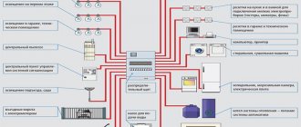
It’s also not worth buying exactly up to a millimeter, so when calculating, they immediately leave 30 cm for sockets, and up to half a meter for lamps. An accurate calculation can be made using a program for designing electrical wiring in a house. In the lower corner of the screen you need to select the “footage” section. A dialog box will open and a picture of the room will appear in it.
The picture will be blank. You need to add the length, width and height of your room to it. In this drawing you need to indicate in detail and accurately where the lamps, sockets, and switches will be located. To draw diagrams and mark electrical wiring, everything must be precisely indicated, because the result of the calculation and the correctness of the diagram depend on this.
2: Circuit Sims
How to choose a built-in electric cooktop: selection guide
Circuit Sims allows you to build electrical circuits online, including in Russian. When the program starts, an animated LRC diagram will appear on the screen. Green indicates positive voltage, gray indicates ground, red indicates negative voltage, and moving yellow dots indicate current.
To turn a switch on or off, you simply press it. If you hover your mouse over any component in the diagram, a brief description and current status will appear in the lower right corner of the window. To edit a component to simulate an electronic circuit, you need to hover your mouse over it, right-click (or Control-click if you're using a Mac), and select Edit.
The Schemes menu contains many examples of different schemes.
Sometimes you can't do it without a professional. but in most cases it’s nice to save money!
7 cool interior posters that even a beginner can draw
This beautiful picture was created in Planoplan.
THE FIRST ONLINE 3D INTERIOR DESIGN PLANNER WITH THE FUNCTION OF CREATING VR LAYOUTS AND REALISTIC RENDERINGS.
Using the Planoplan online service you can:
- create a 3D model of your apartment, country house or office for free;
- develop your own interior design and get realistic 3D images;
- upload your own textures;
- adjust sunlight depending on the location of the object, time of day and season;
- print specifications for materials and furniture used in the project;
- obtain a layout of the walls indicating installed windows, doors, sockets and switches;
- create a virtual tour of the room with the possibility of further viewing on your smartphone and Google Cardboard virtual reality glasses;
- Find out the cost of renovating your apartment or house.
Take a fresh look at your projects using Planoplan's unique VR Panorama feature. Create VR panoramas, scan the generated QR code using your smartphone's camera, download the Planoplan GO! for Google Android or Apple iOS, install your smartphone in Google Cardboard and move into the virtual space that you just made!
Do you want to create an online apartment or house layout for FREE? Choose the color of the walls, flooring, arrange furniture? And get realistic 3D images of interiors in just a couple of minutes?
How to draw a single line electrical diagram
How to draw a 3D drawing: 6 step-by-step examples
It can be downloaded and used on Android and iTunes platforms. All presented elements available in the simulator of electronic circuits in Russian TINA-TI are distributed into six types: passive components, switching switches, semiconductor devices, measuring devices, miniature models of devices of increased complexity. To connect the terminals of the elements to each other, left-click on the selected terminal of the radio element and, without releasing the mouse, drag a line to the next element. The Designer Schematic interface is not complicated. The component database can be checked for compliance at any time and, if necessary, updated directly from the website class=”aligncenter” width=”750″ height=”455″[/img] In this window you can change any attributes circuit element. The simplest elements include the body of the element and the terminals of the element, legs, contacts, etc. Do you want to always be up to date with the news?
There are many free versions. We have found for you the most accessible way to simulate an electrical circuit, see how the system will work and how its parameters will be affected by certain components. There are many free versions.
If you click on an inscription with an error not recognized by the simulator, the part or part of the drawing will be indicated by markers. The program is in Russian. The developers failed to improve the quality and increase the graphical user interface. A simple program for creating electrical circuits
Main menu of the program (Main)
The main menu consists of four blocks: Project, Output, Edit, Histori .
Project block
-The “Save” button saves the current project on the Digi-Key server.
-The “Save As” button saves your project with a new name on the Digi-Key server.
-The “New” button creates a new project. If you have a project open with unsaved changes, the application will prompt you to save the changes before creating a new project.
- The "Open" button shows a dialog box containing previously saved projects. The dialog box also contains a delete button that allows you to delete the project. Highlight the project you want to delete and then click on the Delete .
All of the above functions will be available to you after registering on the program website.
Output block.
— The “Export” button allows you to export the current project as a *.png image file or as a PDF document.
- The Share button allows you to create and publish a web link of your diagram. A web link contains a schematic image file within a web page and is viewable in a standard web browser. The link is open.
-The “Print” button opens the diagram in a new window, which can be printed using the standard browser menu.
Edit block.
— The “Cut” button cuts the selected diagram element to the clipboard.
— “Copy” button — places the selected item on the clipboard.
— The “Paste” button retrieves a previously copied element from the clipboard.
— The “Delete” button removes the selected element from the diagram.
History block
— The “Back” button returns one action back.
— “Forward” button goes to a previously performed operation.
Principles for designing a single-line power supply diagram
When developing and executing as-built documentation, it is necessary to comply with the requirements for similar documents reflected in the regulatory literature, as well as PTEEP and PUE (“Rules for the Construction of Electrical Installations”).
What should a single-line power supply diagram include?
Single-line power supply diagrams should reflect the following information, namely:
the boundary of the area of responsibility of the organization supplying electrical energy and its consumer;
Displaying the zone of balance sheet ownership on the power supply diagram of the facility
input distribution devices (IDUs) or main switchboards, as well as transformer substations on the consumer’s balance sheet with display of ATS (automatic transfer switching) devices, if any;
- electrical energy metering devices indicating the transformation ratio of current transformers when using meters operating on a secondary current of 5 Amperes;
- information about all distribution cabinets available at the facility for both power equipment and lighting systems;
- lengths of main electrical lines, indicating the brand of cables, wires and methods of laying them;
- technical parameters and operating status of all automatic shutdown devices, which include circuit breakers, RCDs and fuses;
- data on all electrical loads connected to the equipment displayed on the diagram, indicating their power, current and cos ϕ.
Option for designing a single-line power supply diagram for an administrative building
Read also: Magnetic square for DIY welding
Design stages
The presence of a single-line power supply diagram is a prerequisite for obtaining permission to connect the construction site to the networks of the power supply organization, therefore, before starting its development, it is necessary to request technical conditions.
In this regard, all work on designing a power supply circuit can be divided into several stages:
- Request and receipt of technical specifications;
- Development of a single-line power supply diagram based on the received documents;
- Coordination of the developed documentation with the organization that issued the technical specifications.
Option for registration of technical specifications for power supply
Design rules, GOST requirements
When designing a single-line power supply diagram, it is necessary to comply with the requirements of GOSTs regulating this process, namely:
- GOST 2.709-89 “Unified system of design documentation (ESKD). Conventional designations of wires and contact connections of electrical elements, equipment and sections of circuits in electrical circuits";
- GOST 2.755-87 “Unified system of design documentation (ESKD). Conventional graphic symbols in electrical diagrams. Switching and contact connection devices";
- GOST 2.721-74 “Unified system of design documentation (ESKD). Conditional graphic designations in schemes. Designations for general use (with Amendments No. 1, 2, 3, 4)";
- GOST 2.710-81 “Unified system of design documentation (ESKD). Alphanumeric designations in electrical circuits (with Change No. 1).”
An option for designing a single-line power supply diagram in accordance with these GOSTs is shown in the following figure.
Calculated single-line diagram of power supply for a residential building
Conventions used in drawing up single-line diagrams
All elements of the power supply system are displayed on the diagram in the form of graphic images, which are regulated by the regulatory literature specified in the previous section of the article. Electrical boxes and cabinets for various purposes are shown as follows.
Electrical installation products (sockets and switches), depending on the design and type of execution, are displayed like this
Electric lighting devices are depicted as follows
Power transformers and current transformers are depicted as follows
Electrical measuring instruments have the following appearance on power supply diagrams, in accordance with GOST
The intersection of electrical lines and the connection points of electrical wiring, as well as grounding, are as follows
Switching devices (circuit breakers and starters, short circuiters and separators, as well as other devices) are depicted as follows
In order to find out how to correctly draw up as-built documentation, you need to study all the requirements of GOSTs or use a special computer program that will take into account all these requirements automatically when using it
Concept and purpose of a single-line diagram
A single-line power supply diagram (OSD) is a document that simplifies the location of power lines and their connection points, switching devices, distribution points, etc. This helps to plot a significant amount of information on one drawing.
Thanks to it, the process of installing an electrical circuit is simplified. It is also necessary for subsequent submission to the relevant authorities to confirm the power supply project for a specific facility. Without OSE it will not be possible to connect to the centralized highway.
Electricity supply to a private house
Features of the electrical circuit diagram
The circuit diagram provides detailed information about the functioning of the electrical part of the object. It examines circuit components individually, displaying performance data and explanatory drawings of the equipment's electrical and electromagnetic communications. The basic power supply design is the basis for other types of documentation.
The drawing up of a basic drawing can be carried out using a spaced or combined method. The first option involves displaying a large number of switching and protective devices. To ensure clarity of the operation of all elements, they are considered separately from each other. When devices are arranged sequentially, each of them is assigned a specific designation in order of priority. If there are separate circuits, they are arranged in parallel.
An example of a single-line diagram for connecting an object
The combined technique is based on the display of all protective and switching devices in close proximity. In the remaining free space in the margins, it is allowed to place a transcript of the conditional graphic elements. In cases where the device is not fully used, it should be reflected in its entirety on the drawing, indicating which part is used. In this case, the part that is not used is allowed to be depicted in a shortened form.
Difference between single line and circuit diagram
OSE is a drawing that shows network components with nominal parameters. They are indicated on the diagram by symbols that are connected by one line, regardless of the number of phases used, which is the main difference from circuit diagrams. Devices are displayed according to established rules.
Schematic single line diagram
Calculated
Developed for objects that are connected to the power supply network for the first time. In the process of drawing up a drawing, you will need to make a number of calculations. They relate to loads and voltage losses, which are necessary for the selection of cable lines, switching equipment, etc.
In this case, the calculation scheme may include the following documentation:
- Structural design of electrical equipment, which reflects the power part between the source and the consumer (connection points, power lines, transformer substations, distribution boards, switching devices).
- The functional diagram clearly shows the operation of the equipment used at the site, and also determines the hazard category. As a rule, it is developed for industrial buildings.
- Fire network location.
- Installation project approved by the relevant authorities.
Electrical supply project for a residential building construction site
Note! The future safety of operation depends on the correctness of drawing up the design diagram, including
electrical and fire.
Executive
It is created for objects with an existing power supply circuit, if it is necessary to replace or modernize individual sections of the circuit. The as-built project displays:
- actual state of the power grid;
- list of equipment involved;
- recommendations for eliminating recorded faults and installing additional equipment.
Electrical supply diagram for a private house
When developing a diagram for large objects, all elements should be reflected separately. First, a single-line diagram of the distribution board of the entire facility is prepared, then for each individual room, indicating the communication lines.
How to make a single line diagram
The electrical single-line diagram of the power supply of an apartment, house, or private enterprise is carried out in accordance with the requirements of GOST 2.702-75. According to the standards, you should get an image of 3 phases supplying the network of a specific room and the group network lines that extend from the supply ones. In this case, the diagram does not need to be detailed; its main purpose is to give an idea of the overall design of the electrical supply system.
Photo - Schematic diagram of the substation
It is thanks to this presentation of information that the end result is a fairly simple drawing that clearly conveys the main parameters of the power supply network. Many novice electricians may doubt the effectiveness of such drawings, because it seems that it is not clear how to display then three-phase or two-phase power.
Everything is very simple: near the line that defines multiphase power, a number and a line through it are placed, as in the photo below. The number in such a diagram is responsible for determining the number of phases, and the line crossed out by oblique segments is the definition of the phase.
In addition to showing the individual wires, it is also important to show additional details of the electrical circuit on the drawing. To designate apartment RCDs, contactors, switches and other additional elements, you also need to familiarize yourself with GOST 2.709, which is provided both in PDF and in plain text
This document indicates generally accepted options for drawing such elements.
Let's look at an example of a single-line diagram of an apartment (can also be used to power a house):
Photo - example of a single-line diagram
To protect group lines from overload and the general circuit of the room from electrical short circuits, circuit breakers are used. They, in turn, are “backed up” in the drawing by overcurrent devices. The circuit must include not only its main components (input cables, grounding cables, RCD), but also sockets and light switches in the rooms.
In the drawing above, you can notice that there are no numbers near the crossed out lines with oblique strokes. Instead, phase determination by the number of strokes is used
If the diagram shows 2 lines, then the power supply is two-phase, if 3, then, accordingly, it is three-phase. But at the same time, single-phase wiring is indicated by one line with one stroke.
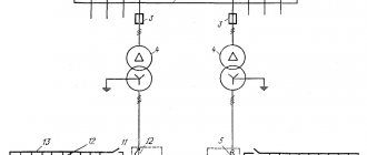
This connection is perfectly demonstrated by the single-line diagram of the KTP transformer:
Photo - single-line diagram of the KTP transformer
Examples of what a one-line standard power supply diagram for a clinic, apartment, country or country house, factory or other premises should include:
- The point where the object is connected to the electrical network;
- All ASUs (input distribution devices);
- The point and brand of the device that is used to connect the room (in most cases, the parameters of the switchboard are also needed);
- It is necessary not only to draw the power cable, but also to mark its cross-section and brand on the diagram; sometimes craftsmen mark the nominal value;
- The project must contain data about the rated and maximum currents of the equipment used at the facility.
It is also very important to use approximate design loads, which may become maximum for a specific power supply network (PBX) of your village or city. Implementation rules may vary depending on the requirements for specific premises
You must pay attention to every detail, because the main requirements for the project are put forward by the electricity supply company. It is the single-line power supply diagram of an enterprise, home, workshop that is the fundamental document according to GOST, which is responsible for the operational responsibilities of different parties
In particular, it is necessary to connect to the local network of a house with an ATS:
Photo - house with avr
To develop a free single-line power supply diagram for a child care facility, private buildings (garages, houses, apartments, kiosks), a multi-story residential building, a plant (SNT), and crew cars, you will need an ESKD. ESKD is a Unified System of Design Documentation.
At home, a single-line electrical diagram is drawn manually or using AutoCAD (drawing program). This software will help you develop a project for any facility (office, shopping pavilion, substation, school, store, cottage, pump station) and consumers.
As a template, we present a single-line diagram of a 10 kV indoor switchgear; by the way, by analogy, an ABBM UPS diagram is being developed:
Photo - single-line diagram of a 10 kW indoor switchgear
To develop a scheme with the help of specialists, you will need to contact the design bureau of your city. There are such institutions in Belgorod, Moscow, St. Petersburg and other large and medium-sized settlements.
Drawing up and approval of the project
The internal electrical wiring project for a private house consists of:
- calculation of power, input devices and required wire cross-section;
- calculation of grounding and lightning protection systems;
- electrical wiring diagrams;
- layout plan for cable lines and power equipment in the building;
- estimates for consumables.
Such a full-fledged project of in-house wiring is done only under a contract with a specialized company with a license. If it then has to be approved by the electrical energy supplier, then the drawings and calculations made independently will not be accepted for consideration.
You can only make an electrical and/or wiring diagram yourself, which will facilitate the work when installing electrical wiring yourself. They schematically indicate protection devices and wire lines to simplify the preparation of estimates and assembly of the entire system.
House wiring diagram
Phase selection
One of the most important considerations in design and wiring diagrams is the type of input voltage. There is no need to analyze specifically here, such as, for example, the numerous pros and cons of a pile foundation. It can be single-phase or three-phase, 220 or 380 Volts. When choosing, you must proceed from the available capabilities of the supply transformer (which can be provided by power engineers) and current-consuming electrical equipment.
In other situations, when a private house does not exceed 100 square meters in area and does not have electric water heaters, you can get by with ordinary single-phase 220 V. The requirements for three-phase electrical wiring are higher. It costs more, but is not always needed. It should be taken into account that 380 V on three phases may be required in the future. And then the approvals will have to start all over again. Here everything needs to be weighed and foreseen in advance.
How to calculate power consumption when wiring
To calculate the total power consumption and the electrical wiring required for this at home, it is necessary to sum up the kilowatts of all household and lighting fixtures in the home. These parameters are available in equipment data sheets and in special tables. Plus, starting loads and 20% in reserve are added here.
The most energy-intensive in a cottage are instantaneous water heaters (about 4–5 kW), electric stoves with ovens (up to 3 kW), electric heaters (1.5–3 kW), vacuum cleaners (about 1.5 kW) and washing machines (about 2–3 kW). 2.5 kW). Ventilation in a private house also consumes a lot if it is made with supply and exhaust and heated air without a recuperator.
Average power consumption of household appliances
Light, especially if it is LED, requires relatively little (up to 0.5 kW). Televisions, computers and other household appliances currently consume approximately the same amount. But all this must be taken into account and added up in order to calculate the total power of the cottage. It is needed to obtain specifications and calculate the cross-section of electrical wiring.
How to calculate the carrying capacity of electrical wiring
Consumer groups
To ensure that the load in the intra-house network is distributed evenly, consumers are divided into several groups in the wiring diagram. For example, one goes to the street lighting of the local area, the second to the outbuildings, the third to the lighting fixtures in the cottage and the fourth to the sockets in it. If the house is large, then such a breakdown can be made by floors and rooms.
Main consumption groups
Each individual line has its own automatic circuit breakers and RCDs (residual current devices). This increases the safety of operation of the home electrical network and simplifies the search for problem points in the system when the protection is triggered. The electrical wiring diagram must indicate all protective devices and the current consumption on the circuit that is powered from each of them.
The group RCD and the wire cross-section behind it are selected so as to correspond to the consumption of a specific group. It is recommended to allocate your own power line for powerful equipment, but for other equipment the number of consumers should not be higher than 5–6 sockets. It is better to include more of them in the project, but with less risk of core burnout due to long-term overloads.
Special programs for drawing single-line power supply diagrams
To correctly prepare technical documentation, you need to study the requirements of GOSTs, but you can use specially developed computer programs. When using specialized programs, all requirements will be taken into account automatically.
- “1-2-3 scheme” is a very easy-to-understand free program. Suitable for students and beginners;
- "AutoCAD Electrical" is a very popular program among experienced professionals, understandable and providing advanced capabilities for developing electrical circuits;
- "Microsoft Visio" is a free program for ordinary people who use the program to draw up a power supply diagram when building a private house;
- XL Pro² is a free program for the design of low-voltage complete devices (LVD);
- "Compass-Electric" is a free program for engineers and specialists in energy complexes;
- Rapsodie is another program for designing low-voltage packaged devices. The program allows you to easily assemble the desired distribution cabinet according to the specified parameters;
- “Eagle” - the program is available in free and paid versions; in the paid package, a version with more advanced technical parameters is available;
- "DipTrace" is software for creating electrical circuits, printed circuit board drawings for creating electronic products.
In order to competently and clearly develop a single-line diagram, it is necessary to strictly follow GOSTs and standards, be able to use modern software products and have an understanding of electrical installations, but it is best to use the services of a specialist.
The result of all of the above
Installation of electrical wiring in a house is carried out for a long time and therefore the diagrams and all projects created in the Electrician program must be saved on your computer. If the network or its individual link fails, you can always look at the electrical wiring design and immediately determine where the wire is placed in order to begin repairs.
It is necessary to have an ammeter, a voltmeter, and an indicator screwdriver so that you can detect a break in the electrical wire in the event of a short circuit.
Do not forget that connection to a private house from the main power line is carried out only by a special team from Energonadzor. Energonadzor employees also install a meter for electricity consumption.
Another important point: if you lack knowledge and skills in the electrical field, it is better not to waste money and call a qualified electrician. This will cost a lot of money, but it will save the whole family and neighbors from possible fires and fires in residential premises.
Principles for designing a single-line power supply diagram
When developing and executing as-built documentation, it is necessary to comply with the requirements for similar documents reflected in the regulatory literature, as well as PTEEP and PUE (“Rules for the Construction of Electrical Installations”).
What should a single-line power supply diagram include?
Single-line power supply diagrams should reflect the following information, namely:
Displaying the zone of balance sheet ownership on the power supply diagram of the facility
- electrical energy metering devices indicating the transformation ratio of current transformers when using meters operating on a secondary current of 5 Amperes;
- information about all distribution cabinets available at the facility for both power equipment and lighting systems;
- lengths of main electrical lines, indicating the brand of cables, wires and methods of laying them;
- technical parameters and operating status of all automatic shutdown devices, which include circuit breakers, RCDs and fuses;
- data on all electrical loads connected to the equipment displayed on the diagram, indicating their power, current and cos ϕ.
Option for designing a single-line power supply diagram for an administrative building
Design stages
The presence of a single-line power supply diagram is a prerequisite for obtaining permission to connect the construction site to the networks of the power supply organization, therefore, before starting its development, it is necessary to request technical conditions.
In this regard, all work on designing a power supply circuit can be divided into several stages:
- Request and receipt of technical specifications;
- Development of a single-line power supply diagram based on the received documents;
- Coordination of the developed documentation with the organization that issued the technical specifications.
Option for registration of technical specifications for power supply
Design rules, GOST requirements
When designing a single-line power supply diagram, it is necessary to comply with the requirements of GOSTs regulating this process, namely:
- GOST 2.709-89 “Unified system of design documentation (ESKD). Conventional designations of wires and contact connections of electrical elements, equipment and sections of circuits in electrical circuits";
- GOST 2.755-87 “Unified system of design documentation (ESKD). Conventional graphic symbols in electrical diagrams. Switching and contact connection devices";
- GOST 2.721-74 “Unified system of design documentation (ESKD). Conditional graphic designations in schemes. Designations for general use (with Amendments No. 1, 2, 3, 4)";
- GOST 2.710-81 “Unified system of design documentation (ESKD). Alphanumeric designations in electrical circuits (with Change No. 1).”
An option for designing a single-line power supply diagram in accordance with these GOSTs is shown in the following figure.
Calculated single-line diagram of power supply for a residential building
Conventions used in drawing up single-line diagrams
All elements of the power supply system are displayed on the diagram in the form of graphic images, which are regulated by the regulatory literature specified in the previous section of the article. Electrical boxes and cabinets for various purposes are shown as follows.
Electrical installation products (sockets and switches), depending on the design and type of execution, are displayed like this
Electric lighting devices are depicted as follows
Power transformers and current transformers are depicted as follows
Electrical measuring instruments have the following appearance on power supply diagrams, in accordance with GOST
The intersection of electrical lines and the connection points of electrical wiring, as well as grounding, are as follows
Switching devices (circuit breakers and starters, short circuiters and separators, as well as other devices) are depicted as follows
In order to find out how to correctly draw up as-built documentation, you need to study all the requirements of GOSTs or use a special computer program that will take into account all these requirements automatically when using it
Recommendations for assembling an electrical panel
Having selected the distribution board required by design, you can proceed to the stage of design and selection of appropriate automation. In this case, you should take into account and continue to adhere to the following recommendations:
- The panel must be filled in accordance with the design documentation. Let's say there are ten machines, a counter and eight RCDs. In this case, the characteristics of the purchased electrical panel must allow it to accommodate this number of blocks. A small reserve is welcome.
- In further orientation according to the diagram, marking groups of elements with tags will help.
- Adhere to the color unity of the wire cores. For phase conductors, the preferred colors are black, brown and gray. The ground conductor is usually yellow-green in color. Zero (neutral) has a blue or cyan color.
- Connect one wire to each terminal of the terminal block. Installing several wires in one socket will worsen the fixation and over time the contact may disappear.
- To make it easier to connect the automation, you can use special tires (combs).
10: Gecko simulations
GeckoCIRCUITS is an online electrical circuit simulator. In addition to the ability to quickly simulate circuits, GeckoCIRCUITS integrates control simulation and thermal simulation through equivalent networks. The main advantages of GeckoCIRCUITS are its extremely high simulation speed and open interface. The software can be integrated into MATLAB/Simulink or other programming environments.
The program does not require installation on gadgets; to launch you only need to double-click the GeckoCIRCUITS.jar file.
Paid programs for drawing electrical circuits
There are many paid graphic editors for creating diagrams, but not all of them are needed for “home” use or for work that is not directly related to design. Paying a lot of money for unnecessary features is not the smartest decision. In this section we will collect those products that have received a lot of good reviews.
DipTrace - for PCB development
For experienced radio amateurs or those whose work involves designing radio products, the DipTrace program will be useful. It was developed in Russia, therefore it is entirely in Russian.
It has a very useful function - it can develop a printed circuit board using a ready-made circuit, and it can be seen not only in two-dimensional, but also in a three-dimensional image with the location of all the elements. It is possible to edit the position of elements on the board, develop and adjust the device body. That is, it can be used both for designing wiring in an apartment or house, and for developing some devices.
In DipTrace you can see what the finished product will look like in 3D format
In addition to the program for drawing diagrams, you will also need to download a library with an element base. The peculiarity is that this can be done using a special application - Schematic DT.
The interface of the program for drawing circuits and creating printed circuit boards DipTrace is convenient. The process of creating a diagram is standard - we drag the necessary elements from the library onto the field, rotate them in the required direction and install them in place. The element that is currently being worked on is highlighted, which makes the work more comfortable.
As the diagram is created, the program automatically checks the correctness and admissibility of connections, matching dimensions, compliance with gaps and distances. That is, all edits and adjustments are made immediately, at the creation stage. The created circuit can be run on the built-in simulator, but it is not the most complex, so it is possible to test the product on any external simulators. It is possible to import a diagram for use in other applications or accept (export) an already created one for further development. So DipTrase diagram drawing software is a really good choice.
If you need a printed circuit board, we find the corresponding function in the menu; if not, the diagram can be saved (it can be adjusted) and/or printed. DipTrace diagram drawing software is paid (there are different plans), but there is a free 30-day version.
SPlan
Perhaps the most popular program for drawing diagrams is SPlan. It has a well-designed interface, extensive, well-structured libraries. It is possible to add your own elements if they are not in the library. As a result, it’s easy to work with; you can master the program in a few hours (if you have experience working with similar software).
The disadvantage is that there is no official Russified version, but you can find it partially translated by craftsmen (the help is still in English). There are also portable versions (SPlan Portable) that do not require installation.
One of the “lightest” versions is SPlan Portable
After downloading and installing the program, you need to configure it. This takes a few minutes, and the settings are saved on subsequent launches. Creating diagrams is standard - find the desired element in the window to the left of the work field, drag it into place. Numbering of elements can be done automatically or manually (selected in the settings). What’s nice is that you can easily change the scale by scrolling the mouse wheel.
After finishing the work, you can save the file as an image that can be printed, and large A4 size diagrams can be created. The main file can be edited later.
There is a paid (40 euros) and a free version. The free version disables saving (bad) and printing (you can get around it by taking screenshots). In general, according to numerous reviews, it is a worthwhile product that is easy to work with.
Paid apps with demo versions
It would seem that specialized programs are the exclusive prerogative of large developers who make software on a commercial, paid basis. To some extent, this is true - the recognized leader is the AutoCAD program, the capabilities of which allow you not only to draw an electrical wiring diagram, but also to work on projects that require the participation of several specialists at once. The created scheme is available to each of them for making changes online, which will immediately be available to other employees of the company. The initial versions of the program were positioned more as a simple “electronic drawing board”, but over time it developed into a powerful tool, consisting of several blocks for specialists in various fields, including electricians.
The domestic analogue is NanoCAD - this is also a drawing program, which, according to user reviews, has no less functionality, but is pleasantly priced, which is several times lower than that of AutoCAD.
Even in this form, they allow you to draw a diagram for installing one or three-phase electrical wiring in an apartment or for a house.
Graphic editor for drawing wiring diagrams and drawing printed circuit boards Eagle - also exists in paid and free versions. The program allows you to work in manual and automatic modes - and a full-fledged single-line wiring diagram is not a problem even for the free version. Unlike previous programs, it can be used on a PC with operating systems of the Linux family (NanoCad is written exclusively for Windows, and AutoCAD can also work under IOs or Android).
Elf is a whole CAD software package from . An electrical engineer will be interested in such capabilities as creating drawing documentation, a large set of symbols and the ability to use your own, calculating the laying of pipes in monolithic panel structures, determining the length of wires and many others. Among the main advantages of the program, users note the rapid creation of specifications and the relative ease of mastering the functionality.
You can also use online services that work for a certain subscription fee, but guarantee excellent results and 24-hour support. The presentation of one of them, CAD5d, is in the following video: