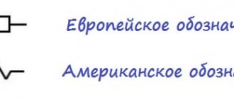
Radio amateurs often have to deal with resistors, and if this is not the first time, then most already know how to determine the characteristics of a circuit element from the markings. But not everyone can do this, and besides, even experts often have to rack their brains when faced with, for example, a printed circuit board with SMD components.
It makes sense to trace the step-by-step evolution of resistors and their markings. First, consider the simplest of them, and only then move on to complex and high-tech SMD resistors.
So, there are three types of similar elements. These are Soviet resistors, which are still used today, however, they are modern - i.e. those that have multi-colored stripes, and of course SMD components.
Methods for determining resistor resistance
If there is no alphanumeric marking, you can use one of the following methods:
- The simplest method is to determine the denomination from the documentation. This is easiest to do if the part is purchased separately and has an accompanying document. If a resistor is part of an electrical apparatus, then its characteristics are indicated on the general electrical diagram either directly next to it (to the right or below) or below in the specification.
- If the resistor is a separate part, then its resistance can be measured with an ohmmeter or multimeter.
- It is possible to accurately identify a part contained in the device only after it has been desoldered.
Alphanumeric marking of resistors
The simplest in terms of evaluation is the Soviet resistor, its power rating is marked directly on the case with the marking MLT-1 and so on, where the unit of measurement is power, and MLT is the type of resistors most popular in Soviet times, and this abbreviation means that the resistor is M - metal film, L-varnished, T-heat-resistant. The power of such resistors depends on their size; the larger the resistor, the more power it can dissipate. These resistors are already an endangered species; they can be found in old electronic equipment.
For MLT type resistors, the unit of measurement of resistance, like others, is Ohms, they are designated as R and E. The exact size of power is indicated by the additional letter “K” - kilo-ohms or the letter “M” - mega-ohms, the measurement system here is quite simple. For example: 33E is 33 Ohms, and 47K is 47 kOhms, respectively, 1M2 is 1.2 Megaohms and so on.
If there is only a number without a letter, then they mean that this resistance is in Ohms, and the tolerance with this designation is 20%. For example, if the number 10 is written, then you have a resistor with a resistance of 10 ohms, and the tolerance is 20%.
Examples of alphanumeric markings of resistors
3E9I or 3R9 means that the resistance is 3.9 Ohms, tolerance 5%
2K2I means that the resistance is 2.2 kOhm, tolerance 5%
5K1S means that the resistance is 5.1 kOhm, tolerance is 10%
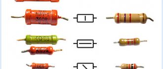
Transistors
Now Soviet transistors, since there are still a lot of them now, although not all of them continue to be made. Their markings are indicated by colored dots of two types, such as:
And these:
There are also these, with code markings:
Of course, you don’t have to remember these tables, but use the reference program, which is in the general archive at the link above. We hope this information about the main parts of domestic production will be very useful to you. The author of the material is St.
Which side to count the stripes on the resistor?
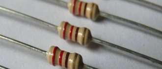
The resistance of the resistor is determined by the first color rings:
- For elements with three stripes, the first two colors are numbers, and the third color is the multiplier.
- For elements with four stripes, the first two colors are numbers, the third color is the multiplier, and the fourth color is the permissible deviation of the resistor resistance from its nominal value.
- For elements with five stripes, the first three colors are numbers, the fourth color is the multiplier, and the fifth color is the permissible deviation of the resistor resistance from its nominal value.
- For elements with six stripes, the first three colors are numbers, the fourth color is the multiplier, the fifth color is the permissible deviation of the resistor resistance from its nominal value, and the sixth is the temperature coefficient.
The color markings on resistors are read from left to right. In this case, you need to correctly determine the left side. As a rule, the first stripe is applied closer to one of the resistor terminals. If the element is small in size and it is impossible to maintain the required proportions for marking delimitation, then the counting is based on the color stripe, which is the widest in comparison with the others.
Additionally, it can be noted that silver and gold colors are never used to indicate the first stripes on resistors. And, as can be seen from the calculation tables, digital values are not specified for these colors.
Online calculator
Interface of the program "Resistor 2.2"
Modern technologies today greatly facilitate the work of both professionals and radio amateurs. In addition to accessible measuring equipment, today in Internet resources dedicated to radio engineering there are a huge number of online calculators for determining the resistance of resistors by marking.
Simple, and generally reliable programs allow you to accurately determine the rating of almost any radio component; more advanced and powerful engineering programs used in packages for design engineers allow you not only to find out the resistance value, but also to find an appropriate replacement and determine the option the performance of the circuit itself.
One of these programs is the Resistor 2.2 program, it is simple, convenient and does not require deep knowledge of computer technology. A simple interface and convenient working elements allow you to work both online and without it.
How to use?
Like most applied engineering programs, the Resistor 2.2 program is an online calculator that allows you to determine the resistance value using various most common types of encoding:
- Standard 4 or 5 color markings.
- Philips branding of various types of resistances.
- Non-standard color coding from Panasonic, Corning Glass Work.
- Regular code marking.
- Regular encoding Panasonic, Philips, Bourns.
After unpacking the archive, the program, which does not require registration, is immediately ready to work. In the window, from the proposed options, the desired parameter is selected and further identification is made using the existing code on the element body.
For ease of identification, an image of the defined encoding is clearly shown in the upper window. Color rings are applied to the body of the radio component in accordance with the values specified by the user, thus making it possible to visually compare the encoding with the real element.
The numerical value of the element's denomination is immediately displayed at the bottom.
Resistor marking calculator with three and four stripes
To determine the resistance of three-band resistors, use the four-band element calculator below. The only peculiarity is that for resistors with three strips the tolerance (error) is always ±20%.
Resistor calculator with four colored stripes:
| 1st lane | 2nd lane | Decimal multiplier | Tolerance | |
| Silver | ÷100 | ±10% | ||
| Gold | ÷10 | ±5% | ||
| Black | 0 | 0 | x1 | |
| Brown | 1 | 1 | x10 | ±1% |
| Red | 2 | 2 | x100 | ±2% |
| Orange | 3 | 3 | x1K | |
| Yellow | 4 | 4 | x10K | |
| Green | 5 | 5 | x100K | ±0.5% |
| Blue | 6 | 6 | x1M | ±0.25% |
| Violet | 7 | 7 | x10M | ±0.10% |
| Grey | 8 | 8 | x100M | ±0.05% |
| White | 9 | 9 | x1G |
| Result: | ± | % |
Marking of Soviet resistors
First of all, let's deal with Soviet resistors.
No matter what you do, you cannot escape from Soviet electronics. Therefore, a little theory will not harm you.
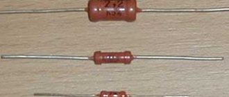
At first glance, we must estimate what maximum power the resistor can dissipate. From top to bottom, below in the photo, resistors by power: 2 Watt, 1 Watt, 0.5 Watt, 0.25 Watt, 0.125 Watt. On resistors with a power of 1 and 2 Watts they write MLT-1 and MLT-2, respectively.
MLT is a type of the most common Soviet resistors, from the abbreviated names Metal Film, Lacquered, Heat Resistant. For other resistors, the power can be estimated based on their dimensions. The larger the resistor, the more power it can dissipate into the surrounding space.
Units of measurement in MLTs - Ohms - are designated as R or E. Kilo-ohms - with the letter “K”, Mega-ohms with the letter “M”. Everything is simple here. For example, 33E (33 Ohms); 33R (33 Ohm); 47K (47 kOhm); 510K (510 kOhm); 1.0M (1 MOhm). There is also a trick that letters can precede numbers, for example, K47 means that the resistance is 470 Ohms, M56 - 560 Kilohms. And sometimes, in order not to bother with commas, they stupidly push a letter there, for example. 4K3 = 4.3 Kilohm, 1M2 – 1.2 Megaohm.
Let's look at our hero. Let's look immediately at the designation. 1K0 or in the words “one and zero”. This means that its resistance should be 1.0 Kilohm.
Let's see if this is really true?
Well, yes, everything agrees with a small error.
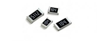
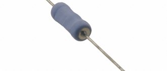
SMD resistors
SMD resistors are miniature resistors designed for surface mounting. SMD resistors are significantly smaller than their traditional counterpart. They are often square, rectangular or oval shaped, with a very low profile.
Electric soldering iron with temperature control Power: 60/80 W, temperature: 200'C-450'C, quality… Read more
Instead of the lead wires of conventional resistors that are inserted into holes on a printed circuit board, SMD resistors have small contacts that are soldered to the surface of the resistor body. This eliminates the need to make holes in the printed circuit board, and thus allows more efficient use of its entire surface.
Why do we need resistor markings?
Considering the fact that SMD resistors are small in size, they cannot be color coded, so manufacturers have developed a different marking method. As a rule, the designation of smd resistors contains three or four numbers; letters may be present.
- Digital marking of resistors is necessary in order to indicate the numerical value of the resistance of the resistor, the last digit is a multiplier. It can also indicate the power that must be raised to 10 to get the final result. For example, resistance can be determined this way: 450 = 45 x 10 equals 45 Ohms.
- If the marking is EIA-96, then this means that the resistors are high precision. This standard is intended for resistors that have a small resistance of 1%. This marking system has three elements: 2 numbers that indicate the denomination code, and the letters are a multiplier. The numbers are a code that gives the resistance number. For example, code 04 may indicate 107 ohms.
For convenient calculation, a calculator is used that will help you quickly find the resistance value. To calculate, you need to enter the code that is on the component and the resistance will immediately appear below. This calculator is suitable not only for the standard. To more accurately check the resistance, it is best to use a multimeter for calculations. Read here which is the best multimeter to choose.
What characteristics does it show?
The most important characteristics of the parts are the value of the nominal resistance, the tolerance on the value and the temperature coefficient. Any of these characteristics is related to the power of SMD resistors and the resistance between it and the ambient temperature. In some areas, even noise characteristics are taken into account.
Important! Component characteristics include stability, voltage, resistance dependence and frequency parameters.
To understand this issue in detail, you need to carefully study all the characteristics:
- The value of the nominal resistance. The tolerance on the nominal resistance value is specified as a percentage. This value indicates the resistance of the resistor under external influences on it.
- Temperature. As a rule, the natural temperature is +20°C and there should be normal atmospheric pressure. SMD resistors are produced with a tolerance for nominal resistance ranging from ±0.05% to ±5%.
- Accuracy. The most accurate resistors can be considered those that are calculated using the formula TKS=DR/(R*DT). DR means the change in resistance when the temperature changes by the amount DT, R is the nominal value of the resistance.
If the components can be calculated using this formula, then this means that they have the highest accuracy.
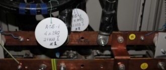
Sun
(B) moisture-resistant (C) resistance; decoding (B)highly (C)stable is also found.
These carbon resistors were created in 1946-47, as a result of the work of M.M. Stolyarov and others on modernizing samples of German resistors (and others). In the 50-60s of the last century, they were the most popular domestic resistors and were used almost everywhere, from household to special equipment.
The technology for manufacturing BC resistors is based on the principle of the formation of a film of graphite-like crystallites on the surface of ceramic bases. This film is formed as a result of thermal decomposition without access to oxygen (pyrolysis) of gaseous hydrocarbons.
The base of the resistors is: for resistances with a power of up to 2 W - a porcelain rod; For high-power resistances, in order to lighten the weight and improve heat dissipation conditions, ceramic tubes are used. A thin conductive layer of carbon is applied to the surface of the base. Carbon is applied to the surface of the ceramic by pyrolytic decomposition of hydrocarbon vapors at a temperature of 900-1000 ° C under vacuum or in an inert gas environment. In this case, fine-crystalline graphite diffuses into the surface layer of ceramics. The high stability of the main parameters of BC resistors is due to the absence of binders or components of organic origin in the conductive layer. Diffusion of graphite into ceramics makes it possible to obtain carburized workpieces with a resistance from tenths of an ohm to 100,000 ohms. A further increase in resistance by 4–10,000 times is achieved by cutting a spiral groove on the surface of the carburized rod.
The ends of the resistors are reinforced with contact leads, and the conductive carbon layer is coated with an insulating moisture-resistant varnish or enamel. The contact terminals are made of copper wire or thin brass tape.
Manufacturers of early releases are the St. Petersburg State Research Institute of Resistors and Capacitors (later became the Girikond Research Institute) and the St. Petersburg plant No. 130 MPSS (later Leningrad Ferrite). In 1949, NII-34 reported that “assistance was provided in the development of resistance type “VS” to plant No. 130 and workshop No. 3 of the pilot plant [at NII-34 - K.]”
The bulk of the resistors were produced by the Novosibirsk Radio Components Plant (aka PO Oxid), (Bogoroditsk, Tula region), Leningrad and the 1st Moscow Radio Components Plant.
General description Electrical parameters Development Early release resistors Production technology
The BC resistor is a ceramic rod or ceramic tube, on the surface of which a layer of carbon is applied, which has a high resistivity. High-resistance resistors have a thinner carbon layer than low-resistance ones. In practice, the thickness of the carbon layer for the described resistances ranges from several thousandths of a micron to 0.2 microns.
A layer of carbon is deposited on the ceramic in special furnaces using the pyrolysis method: hydrocarbon gas or steam introduced into the furnace decomposes under the influence of high temperature and carbon is deposited on the surface of the ceramic rods. For resistances with ratings of 100-240 ohms and higher, a spiral groove 0.3-0.8 mm wide is cut through the entire thickness of the carbon layer, turning the layer into a ribbon spiral.
Silver-plated or tin-plated brass clamps with silver-plated or tin-plated brass tape tails are tightly pressed onto the ends of the carburized rod (in resistors of early releases, the leads could be made of wire). The entire carburized rod, together with the clamps, is covered with moisture-resistant organic enamel of green (most likely it is epoxy enamel No. 272) or (rarely) red. At the same time, the quality of green resistances is better.
Resistances BC-0.25 and BC-0.5 with ratings above 0.5 MOhm are unreliable in operation, since with a large number of turns of the cut spiral they have the thinnest layer of carbon, which is easily destroyed under conditions of high humidity and overheating. Therefore, the use of such resistances in equipment is not recommended. If it is necessary to use BC resistors with rated values greater than 0.5 MOhm, you can use resistors with higher rated powers.
Due to the fact that the thickness of the carbon layer of BC resistances remains less than the penetration depth of alternating current in a wide range of frequencies, their active resistances up to frequencies of the order of several megahertz are practically no different from the resistance values measured with direct current or low-frequency alternating current. At higher frequencies, the active resistance decreases because the passage of current begins to be noticeably affected by the capacitances between the edges of the turns of the conductive layer; these capacitors seem to bypass the turns and reduce the effective value of resistance. Thus, for threaded resistors BC-0.25 and BC-0.5, which are used primarily in high-frequency circuits of radio receivers, at a frequency of 10 MHz the active resistance decreases by approximately 10%, and at a frequency of 100 MHz it decreases by approximately 3 times.
Most low-resistance non-wire resistors begin to increase in active resistance immediately after they are released. This aging process is completed mainly in the first six months to a year, during which the value of active resistance usually changes by no more than 1% of the original one.
Under normal climatic conditions, the heating temperature of the conductive layer of BC resistors does not exceed 395-400° K, which is considered the maximum permissible when operating the resistor for several thousand hours. The greatest overheating at rated load power occurs in resistors VS-5 and VS-2. Resistors with a nominal dissipation power of 0.25, 0.5 W have more favorable thermal conditions, their overheating is 40-65° K. The heating temperature of the conductive layer of pyrolytic carbon is limited due to the fact that at elevated temperatures oxidation processes with oxygen occur in it, and this leads to an increase in the resistivity of the conductive film (with increasing temperature, oxidation processes accelerate). In addition, heating the resistor leads to damage to the protective enamel coating, which, when exposed to elevated temperatures, becomes brittle and can peel off or become charred.
The maximum operating voltage for low-resistance resistors is determined by thermal processes in the conductive layer, i.e., the rated power and rated resistance of the resistor. Typically, the maximum operating voltage of a resistor is the voltage at which its reliable operation is ensured without breakdown or overlap along the surface between the resistor terminals, as well as in the spaces between the turns of the spiral. Thus, the maximum operating voltage is indicated only for high-resistance resistors, for which heating at rated power is insignificant. In addition, the operating voltage of the resistor is associated with the need to limit: a) the voltage gradient in the conductive layer, which determines the level of intrinsic noise and the voltage coefficient of the resistor; b) current density through the conductive element-terminal contact, which also determines the resistor’s own noise level.
The voltage factor of carbon resistors usually does not exceed 1.5-2%. As the voltage increases, the resistance of the resistor decreases, i.e., the voltage coefficient is negative. This is due to an increase in the conductivity of the gaps between individual particles of pyrolytic carbon.
The load factor, which affects the change in the resistance of the conductive element under the influence of applied voltage and heat, depends on the electrical load of the resistor and TCS and for carbon resistors does not exceed 6%. High-resistance resistors have a lower load factor due to the fact that at the maximum operating voltage they are underloaded in terms of power. The load factor of carbon resistors is most often negative, since they have a negative TCR. Positive load factor values (usually very small) are relatively rare in carbon resistors; they are associated, as a rule, with defects in the structure of the conductive film (defects in carburization, cutting) or in the protective coating.
Electrical parameters (for later releases)
| The range of produced ratings is 10 Ohm ... 10 MOhm |
| The maximum permissible power dissipation is 0.125; 0.25; 0.5; 1; 2; 5 and 10 W (there were also small-scale ones with 60 W) |
| Operating temperature -60 … +125°С |
| The moisture resistance coefficient for resistors with a nominal value of up to 1 MOhm is no more than ±12%; for resistors over 1 MOhm - no more than ±20% |
| Aging rate no more than 4% |
| EMF noise - no more than 5 µV/V |
Reference sheet for them, as well as data from the 1968 and 1983 industry directories.
Over the course of their long life, these resistors have been repeatedly refined and modernized. Thus, the first releases had a completely different design of the terminals, the caps were fastened by riveting, and the terminals themselves could be made of either tape or wire. Probably, some Soviet factories produced these resistors on the original “trophy” lines of Dralowid (which had an option with wire leads and riveted caps) and Siemens (Karbowid resistors, with pressed caps), exported from Germany.
At the end of the 60s, a version with an axial arrangement of pins appeared - BC-a.
The denominations of early issues started from only 51 Ohms. And resistors with a nominal value of up to 1 kOhm and over 2 MOhm with a spread of 5% were not made at all. In general, the 1950 instruction “When ordering, the number of resistances according to the 1st accuracy class should not exceed 20% of the ordered quantity” seems to hint to us about the level of technology of these resistors at that time...
In the mid-50s, the lower limit was pushed back to 27 Ohms, and already in the 60s - to 10 Ohms; and restrictions on the accuracy of resistors at the edges of the range of values were removed.
There were changes in a number of capacities. Resistors with a power of 0.125 W appeared only in the late 50s (they were also produced under the brand name ULM-0.12). And in the late 50s - early 60s, 60 W options were also produced (the books are marked “... but they are used very rarely”). In the 1959 directory there are also resistors with a power of 15 and even 100 W, produced according to special technical conditions! Moreover, judging by this reference book, they were very different from conventional resistors - both in the range of nominal resistances and in other parameters - moisture resistance, maximum voltage, etc.
Almost all electrical parameters have also been improved. Resistance to external influences, thermal stability, permissible stresses, shelf life and minimum operating time (almost twice!)…
There have even been changes in the markings of these resistors. So, in the first years, on resistors of this type with a tolerance of 20% (III accuracy class, according to the terminology of that time), the percentage was not indicated.
(photo from the “Portable Retroradio” forum)
Production technology
The manufacture of BC resistances is carried out on a mechanized production line, which includes specialized equipment and workstations for performing the following operations: 1) preparation of foundations; 2) carburization; 3) protective varnish coating; 4) reinforcement; 5) electrical calibration according to the original ratings; 6) cutting grooves to obtain the required denomination; 7) bookmarking in cassettes; electric training; 9) enamel coating and drying; 10) calibration according to tolerances; 11) control measurements; 12) marking; 13) drying the marking; 14) securing in paper tape; 15) packaging of finished resistors in cardboard boxes.
To obtain high stability of resistors, the ceramic bases used in the manufacture of resistors must have appropriate properties. The surface of ceramic bases must be chemically homogeneous and free from mechanical defects (cracks, chips). The uniformity of the ceramic microrelief is achieved by special treatment - etching in a solution of hydrofluoric acid or mechanical treatment with a fine abrasive. The ceramic material must be dense and have no open or closed pores. The composition of the ceramic material should not contain significant amounts of alkali metal oxides, since intensive electrochemical processes develop in ceramics containing potassium and sodium oxides, which can lead to the destruction of the conductive film. Bases intended for resistances from 10 to 200 ohms are etched in a two percent solution, and for resistances from 200 to 1500 ohms - in a one percent solution of hydrofluoric acid. Etching is carried out in a bath, the inner surface of which is coated with an acid-resistant material. In the bath there is a rotating drum made of sheet PCB or plastic mass, which is highly resistant to hydrofluoric acid. The drum walls have a large number of small holes. The drum is loaded with 50% of its volume through the hatch. After loading the drum, the bath is filled with an aqueous solution of hydrofluoric acid of the concentration indicated above. When the drum rotates, the bases move, which speeds up the etching process and ensures its uniformity. The latter is necessary for uniform distribution of the conductive layer on the surface of the base. Removal of traces of hydrofluoric acid and etching products is carried out by washing in the same bath. Before washing, the hydrofluoric acid solution from the bath is pumped back into the tank in which it is stored, and first cold water (10-15 ° C), and then hot (80-90 ° C) and, finally, cold, distilled water is passed through the bath. The rinsing lasts 15 minutes, during which a double exchange of cold, hot and distilled water is carried out. During washing, the drum with loaded bases rotates continuously. Drying of the bases is carried out in a centrifuge, the inner surface of which is covered with textolite or plastic mass. Bases for resistors whose nominal value is above 1500 ohms are first cleaned with ground quartz sand. Cleaning is carried out in a drum with walls made of hardwood. One third of the drum volume is filled with bases, and the other third with sand. The sand is separated from the bases on sieves. Washing in cold, hot and distilled water, as well as removing water, drying is carried out according to the previously described technological process. Bases for resistances from 1500 to 6000 ohms, after cleaning with sand, are subjected to short-term etching (6-8 minutes) in an aqueous solution of hydrofluoric acid, the concentration of which is 0.25%, followed by rinsing. The prepared substrates are placed in lockable plastic boxes, and from this moment until a protective layer of varnish is applied, their outer surface must not be touched with hands without rubber gloves.
The pyrolysis process is carried out in special vacuum furnaces, which are a pipe made of fused quartz or glazed ceramic with a length of 1.7-2 m and a diameter of 70-100 mm. The ends of the pipe are tightly closed with removable vacuum-tight covers, which have fittings for connecting a system that provides the supply of hydrocarbon vapor while simultaneously pumping out air. In order to obtain the necessary vacuum seal, the ends of the pipe are usually air or water cooled. The heating element of the vacuum furnace is a nichrome winding located on top of the middle part of the pipe. The winding is carried out along the ceramic pipe with an uneven pitch to ensure uniform temperature distribution in the working area of the furnace. Measurement and control of the temperature in the chamber where pyrolysis is carried out is carried out by an optical pyrometer and a thermocouple, which is used to automatically maintain the required pyrolysis temperature using a thermostat. To carry out pyrolysis, ceramic bases are loaded into the furnace, the pipe is heated to a temperature of 930-1000°C (depending on what resistance rating is intended to be obtained), and at the same time a vacuum of 10-20 N/m2 is created in the furnace. The rate of the pyrolysis reaction is regulated by special devices (capillaries) differentially depending on the thickness of the carbon film for each type of resistor. To obtain the specified resistance of the resistor bases, the number of blanks is strictly regulated. So, for example, for resistors with a nominal power of 0.25 W, 5000 pieces of ceramic bases are loaded, and for resistors with a power of 2 W - only 450 pieces. When the required temperature is reached, hydrocarbon vapor (heptane) is supplied with simultaneous pumping of decomposition products. To ensure uniform carburization of all ceramic bases during the pyrolysis process, the direction of supply of heptane changes and the bases are mixed by rotating the furnace around its longitudinal axis. The carburization process can last from 0.3 to 8 hours. Depending on the duration of carburization and the amount of evaporated heptane, layers of pyrolytic carbon with a surface resistance from tenths of an Ohm per square surface to 30-35 kOhm are obtained on ceramic bases. Workpieces with surface resistances above these values are excluded from further production processes, since the temperature coefficient values, noise levels and stability of very thin films do not meet specifications. Upon completion of evaporation of the required amount of hydrocarbon, the vapor inlet is stopped and the heating of the furnace is turned off. After the furnace has cooled to approximately 600-700 ° C, the vacuum pump is turned off. Air intake into the furnace and its unloading can be carried out at a temperature not exceeding 250° C. Cooling the furnace to the specified temperature lasts about three hours. On the bases of the tubular structure, a layer of carbon is also deposited on the inner surface of the tube. This layer is removed using a sand blast using a sandblasting machine.
The disadvantages of the described (chamber) carburization method include: 1) a long technological process (loading, leak testing, heating, carrying out the pyrolysis reaction, cooling, unloading, cleaning); 2) the difficulty of maintaining a vacuum; 3) a large spread of resistance values in one load, which makes it difficult to obtain resistances of a given value when spiral cutting cannot be used (low-resistance ratings). Therefore, along with the use of vacuum installations, a method of carburization in a protective atmosphere of nitrogen (N2) without the use of vacuum was developed. The carburization process is carried out continuously, which is the fundamental difference between this method and the previously described one.
With the flow method, the bases are pushed one after another through a heated tube using a mechanical pusher, into which a working mixture of methane (CH4) and nitrogen is introduced. The central part of the tube is heated to the temperature required for the pyrolysis process (930-1000°C). The working mixture is removed into the atmosphere within the working area to prevent its decomposition and carbon deposition on insufficiently heated substrates. For the same purpose, a counterflow of nitrogen is created at both ends of the tube, which prevents access of the working mixture to insufficiently heated or already cooled bases. The amount of deposited carbon is regulated by the percentage (from 10 to 30%) of methane in the working mixture, the intensity of its supply and the speed of passage of the bases through the chamber. To obtain low-resistance resistances (below 500 ohms), the continuous process becomes less productive than the vacuum one. However, the continuity of the process and the possibility of obtaining a given resistance value within +20% remain unchanged. To obtain a more uniform deposition of carbon, the tube through which the bases are pushed is constantly rotated around the longitudinal axis by approximately 45°. Similar designs of installations for continuous carburization may have a vertical tube arrangement. The in-line method increases the productivity of the carburizing operation, especially for high-resistance resistors. However, the electrical parameters of resistors obtained using this method are inferior to the parameters of resistors obtained by carburization in vacuum chambers.
After carburization, in order to protect the conductive layer from mechanical damage and from exposure to the atmosphere, the middle part of the blanks used for high-resistance resistors is coated with KF-20 protective varnish. Next, the workpieces are dried with infrared rays while moving along the conveyor.
The next operation is the reinforcement of the terminals. A suspension of colloidal graphite or molecular silver is applied to the edges of the blanks used for the production of precision and low-resistance resistors to create reliable contact with low transient resistance between the conductive carbon layer and the metal terminal, then the terminals are reinforced. The contact output assembly of BC resistors is produced by contact welding of silver-plated copper or tin-bismuth-coated wire and cap.
After reinforcement of the leads, special automatic devices are used to calibrate the workpieces into groups according to the resistance value, with an accuracy of at least +2% of the nominal value.
The resistances, calibrated by groups, are used for cutting spiral grooves to increase the value of ohmic resistance by lengthening the current path and reducing the cross-section of the carburized layer. The grooves are cut with a thin abrasive wheel, the cutting part of which is sharpened with a diamond. Spiral cutting is performed with thread pitch from 0.7 to 20 mm. Low resistance resistors are obtained directly from reinforced blanks. So resistors VS-0.125 (ULM-0.12) with a resistance of up to 220 Ohms, VS-0.25 and VS-0.5 - up to 510 Ohms, VS-1 and VS-2 - up to 750 Ohms and resistors VS-5 and VS-10 - up to 1 kOhm are performed without cutting. Non-helical resistors with higher resistances cannot be used as they will have higher TCR and load factor values. To obtain a high nominal resistance with a low TCR, it is advisable to use blanks for low-resistance resistors. In this case, the length of the spiral increases, which leads to a decrease in voltage gradients in the conductive element. However, with a very small cutting pitch, the mechanical strength of the conductive layer is reduced, so workpieces with high resistances and, accordingly, large TKr are used. The highest nominal resistances are obtained when cutting workpieces along a helical line with different (variable) pitches (0.6-4.2 mm). When cutting, a spiral tape is formed from a conductive layer, the width of which is determined by the cutting pitch, and the length depends on the number of turns. Cutting allows you to increase the resistance of conductive elements by several hundred and even thousand times. To adjust the value of low-resistance resistances without spiral cutting, grinding of longitudinal slots is used. The number of slots does not exceed 6-8, which allows increasing the resistance value by 25%. After cutting the resistance, if required, they are adjusted (adjusted) to the required resistance value by mechanically erasing the surface layers of carbon. Adjustment is carried out by pressing the felt strip against the carburized layer and moving it evenly over the entire surface of the resistance rotating around the longitudinal axis. In this case, greater accuracy of adjustment can be achieved, since during adjustment the resistance value changes within small limits (10-30%), and the measurement is carried out by precise bridge circuits.
After cutting, the resistors are subjected to short-term electrical training when applying an electrical load several times higher than the rated power. This operation is carried out to stabilize the conductive layer, burn out conductive “bridges”, identify low-quality conductive layer and other defects. During the electrical training process, unusable resistors are rejected.
The next technological operation—coating the conductive surface of the resistor with two or three layers of EP-96 epoxy-cresol varnish or glyphthalic oil enamel—is carried out on high-performance conveyor units with simultaneous drying. Coating is carried out by dipping products mounted in special cassettes. In the same cassettes, drying is carried out with a stream of air heated to 430-440 ° K. Resistors intended for tropical operating conditions are manufactured with a reinforced protective coating in four layers. Enamel coating of large resistances with tubular bases (VS-5, VS-10, etc.) is carried out using the spray method.
After the protective coating has dried, the resistors are calibrated according to accuracy classes and their own noise level.
Marking of resistors is carried out on special marking machines. Then the resistors are placed in packaging cards and dried in a conveyor oven with infrared lamps for 20 - 30 minutes at a temperature of 440 ° K.
Most technological and control-measuring operations are carried out using automatic and semi-automatic machines, for example, the assembly of resistors, which accounts for 70-90% of the total labor intensity of manufacturing a product.
Early release resistors
The design of these resistors has changed a lot over the years, most notably the terminal assembly.
Thus, for low-power options, the leads were initially secured by riveting, while the leads themselves could be either wire or plate.
The design of the cap for resistors with a power of 1-2 watts also differs from the later ones. In the early ones, as a rule, it covers the entire end, and it could be either with riveted leads or with welded ones:
But powerful, 5-watt resistors had different clamp designs. The early versions did not have “ears” on the clamps and thick square washers were placed under the rivets (so that the clamp would not bend at the rivet, since the metal of the clamp in the early BC-5 is thinner):
(photo by Vladimir, Perm)
(photo by Vladimir, Perm)
(photo by Vladimir, Perm)
VS-60 is, of course, a bomb! to understand the scale, the usual two-watt power supply is also present in his photographs...
Sources:
1. Ginkin G.G. Handbook of radio engineering, M. Gosenergoizdat, 1948 2. V. N. Loginov. Handbook of radio components. M.-L., Gosenergoizdat, 1949. (Mass radio library. Issue 41) 3. V.T. Renne. Non-wire carbon-ceramic resistance of surface type - “Electricity” 1949, No. 12. 4. Elements and parts of amateur radio receivers (Reference book). Under the general editorship of V.V. Enyutina. M.-L., Gosenergoizdat, 1950. (Mass radio library. Issue 55) 5. Levitin M.A. Capacitors and resistances. Catalog. Bureau of Technical Information. Moscow, 1950 6. A.D. Frolov. Broadcast Receiver Designer's Handbook. M.-L., Gosenergoizdat, 1951 7. Amateur radio reference book. Ed. IN AND. Shamshura. - M.-L.: Gosenergoizdat, 1951 (MRB 128) 8. D.D. Sachkov. Design of radio equipment. M.-L., Gosenergoizdat, 1951. 9. A.S. Balakshin. Handbook of sound film amplification devices. Under the general editorship of K.A. Lamagin. 3rd edition, revised and expanded. - Goskinoizdat, Moscow, 1953 10. Amateur Radio Handbook. Under the general editorship of A. A. Kulikovsky. - M.-L.: Gosenergoizdat, 1955 (Mass Radio Library, issue 222) 11. Amateur Radio Handbook. Second edition. Under the general editorship of A. A. Kulikovsky. - M.-L.: Gosenergoizdat, 1958 (Mass radio library, issue 286) 12. Tereshchuk R.M., Dombrugov R.M., Bosy N.D. Amateur Radio Handbook. Under general ed. V.V. Ogievsky. - Kyiv: State Publishing House of Technical Literature of the Ukrainian SSR, 1957 13. Malinin R.M. Capacitors and resistances. M. Voenizdat, 1959. 14. V.A. Zhukov. Radio equipment production technology. - M.-L.: Gosenergoizdat, 1959. 15. Handbook for a beginner radio amateur. Under the general editorship of R.M. Malinina. - M.-L.: Gosenergoizdat, 1961 (MRB 400) 16. Amateur Radio Handbook. Third edition. Under the general editorship of A. A. Kulikovsky. - M.-L.: Gosenergoizdat, 1963 (Mass radio library, issue 394) 17. Lomanovich V.A. Handbook of radio components (Resistors and capacitors). - M., DOSAAF publishing house, 1965. 18. Verkhopyatnitsky P.D. Electrical elements of ship radio-electronic and computing devices. L.: Shipbuilding, 1967. 19. Directory. Part III. Issue 3. Resistances (resistors). Revision 2-67. 1967. 20. Panfilov N.D. Cinema amplifiers. Publishing house "Art", Moscow, 1968. 21. Amateur Radio Handbook. R. M. Tereshchuk, R. M. Dombrugov, N. D. Bosy, S. I. Nogin, V. P. Borovsky, A. B. Chaplinsky. In two parts. Ed. 6th. “Technique”, 1970. 22. Alekseev N.G., Prokhorov V.A., Chmutov K.V. Modern electronic devices and circuits in physical and chemical research, ed. 2nd, revised and expanded. Ed. "Chemistry", 1971. 23. List of radio components. Ministry of Trade of the RSFSR. Posyltorg. Central trading base. Moscow, 1971 24. Martyushov K.I., Zaitsev Yu.V. Resistor production technology. Educational manual for the specialty “Semiconductors and Dielectrics”, M., “Higher. school", 1972 25. Amateur radio operator's brief guide. Berezovsky M.A., Pisarenko V.M. - Kyiv “Tekhnika”, 1975 26. Radio components, radio components and their calculation. Ed. A.V. Kovalya. M., “Sov. radio", 1977 27. Handbook on elements of radio-electronic devices. Ed. V.N. Dulina, M.S. Beetle. M., “Energy”, 1977 28. Volgov V.A. Parts and components of radio-electronic equipment. Ed. 2nd, revised and additional M., “Energy”, 1977 29. Resistance. Directory. Volume 1. All-Russian Scientific Research Institute "Electronstandart", 1977. 30. Zhitnikov V.S., Kurkin V.I. Equipment for the production of resistors. - M.: Energy, 1979. 31. Resistors: (reference book) / Yu.N. Andreev, A.I. Antonyan, D.M. Ivanov and others; Ed. I.I. Chetvertkova. - M.: Energoizdat, 1981. 32. Bodilovsky Z.G. Handbook of a young radio operator: 4th ed., revised. and additional - M.: Higher. school, 1983. (Vocational education. Library series) 33. Resistors. Groups 6010, 6020. Collection of reference sheets. RM 11 074.022.1-83. Official publication. All-Russian Research Institute "Electronstandart", 1984. 34. Gorobets A.I. and others. Handbook on the design of radio-electronic equipment (printed units) / A.I. Gorobets, A.I. Stepanenko, V.M. Koronkevich. - K.: Tekhnika, 1985 35. Resistors: Directory / V.V. Dubrovsky, D.M. Ivanov, N.Ya. Pratusevich and others; Under general editorship I. I. Chetvertkova and V. M. Terekhova. - M.: Radio and Communications, 1987. 36. Dimitar Rachev. Amateur Radio Handbook. Derzhavno publishing house "Technique". 1990. 37. Resistors: Directory / V. V. Dubrovsky, D. M. Ivanov, N. Ya. Pratusevich and others; Ed. I. I. Chetvertkova and V. M. Terekhova. — 2nd ed., revised. and additional - M.: Radio and Communications, 1991 38. Aksenov A. I., Nefedov A. V. Elements of household radio equipment circuits. Capacitors. Resistors: Directory. - M.: Radio and Communications, 1995 - (Mass Radio Library; Issue 1203).
home
Standard sizes of SMD resistors
Basically, the term frame size includes the size, shape and terminal configuration (package type) of any electronic component. For example, the configuration of a conventional chip that has a flat package with double-sided pins (perpendicular to the plane of the base) is called DIP.
SMD resistor sizes are standardized, and most manufacturers use the JEDEC standard. The size of SMD resistors is indicated by a numerical code, for example, 0603. The code contains information about the length and width of the resistor. So in our example code 0603 (in inches) the body length is 0.060 inches by 0.030 inches wide.
Organizer for SMD components Great for storing 1206/0805/0603/0402/0201... 2 in 1 soldering station with LCD display Power: 800 W, temperature: 100...480 degrees, air flow... Set of SMD resistors 1206 100 pcs., 0R…10M 1/2 W, 0, 1, 10, 100, 150, 220, 330… Professional SMD component tester Digital tester for checking SMD resistors, capacitors, diodes…
The same resistor size in the metric system will have code 1608 (in millimeters), respectively, the length is 1.6 mm, the width is 0.8 mm. To convert dimensions to millimeters, simply multiply the size in inches by 25.4.
SMD resistor sizes and their power
The size of the SMD resistor depends mainly on the required power dissipation. The following table lists the sizes and specifications of the most commonly used SMD resistors.
Products of MLT LLC
Main technical characteristics:
- 21 methods for determining hemostasis indicators: 16 clotting tests, 5 chromogenic tests
- Quality control: built-in quality control of calibrations, construction of Levy-Jennings maps
- Touch graphic screen
- Built-in thermal printer
- Options: USB barcode scanner
- 4 versions:
- APG2-03-P – two-channel coagulometer with built-in printer
APG2-03-Pkh – two-channel coagulometer with a built-in printer and an additional channel for chromogenic tests
- APG4-03-P – four-channel coagulometer with built-in printer
- APG4-03-Pkh is a four-channel coagulometer with a built-in printer and an additional channel for chromogenic tests.
Optical-mechanical coagulometers (analyzers of hemostasis indicators) with a touch graphic screen and a channel for chromogenic tests APG2-03-P, APG2-03-Pkh, APG4-03-P, APG4-03-Pkh
Sets of paints and other reagents have been prepared for the most common painting techniques.
- Romanovsky staining: ROM-STANDARD-MLT, ROM-EXPRESS-MLT
- Papanicolaou staining: PAP-DIFF-MLT
Sets of reagents for staining microscopic preparations
Programmable painting machines of the second generation AFOMK-16-25, AFOMK-16 are compact, have unique simple mechanics with high reliability and functionality. The devices make it possible to implement the most complex techniques, including Papanicolaou cytological staining, histological techniques, and provide productivity sufficient for most laboratories. Main technical characteristics:
- Number of stations - 16, of which - one automated loading station, one drying station, one station with a flow bath (connection to a water supply, or to a submersible pump for pumping distilled water or a buffer solution)
- The working chamber is ventilated, with the ability to connect to centralized ventilation, it is possible to use an absorbent filter
- Tripods for 25 glasses made of stainless steel.
- Processing modes: exposure, activation, dipping, loading and unloading tripods
- Control and programming via color touch screen
- The maximum number of programs is 32 (the number of steps is up to 30).
EMKOSTAINER AFOMK-16EMKOSTAINER AFOMK-16-25
The products of MLT LLC have registration certificates of the Russian Federation.
Standard color coding
In order to correctly mark and tables have become widely used, international standards have been adopted, according to which from 3 to 6 stripes can be applied to a resistor, each of which has a specific purpose.
Let's consider the features of standard color marking:
- Marking with 3 stripes is carried out as follows: the first 2 rings indicate numbers, 3 – the multiplier. There is no 4 ring, since for all such resistors the accepted deviation is 20%.
- 4 rings – marking, which is slightly different from the previous case. The last ring means deviation. All values are selected using a special table. In this case, the deviation is 5%, 10%.
- 5 rings means the minimum deviation rate, up to 0.005%. In this case, the first 3 rings represent numbers, which then need to be multiplied by a factor. You can find the multiplier using the same table; you need to look for the color value of 4 rings.
- There are resistor options that have 6 rings. Their decoding is carried out in the same way as with 5 rings, only the last of them means the temperature coefficient of change. This value determines how much the resistance value will change as the temperature of the resistor body increases.
Not all tables have a column for decoding the 6th ring, which is worth considering.
Four strip resistors
1st digit2nd digitMultiplierInaccuracy1st digit1 Brown2 Red3 Orange4 Yellow5 Green6 Blue7 Purple8 Gray9 White2nd digit0 Black1 Brown2 Red3 Orange4 Yellow5 Green6 Blue7 Purple8 Gray9 WhiteMultiplierx1 Blackx10 Brownx100 Redx1k Orangex10k Yellowx100k Greenx1M Bluex10M Purplex100M Grayx1G White÷10 Gold÷100 SilverAccuracy± 1 % Brown ± 2% Red ± 3% Orange ± 4% Yellow ± 0.5% Green ± 0.25% Blue ± 0.10% Purple ± 0.05% Gray ± 5% Gold ± 10% Silver Resistance: Ohm (Ω) Accuracy: Minimum: Ohm (Ω )Maximum: Ohm (Ω)
Five strip resistors
1st digit2nd digit3rd digitMultiplierInaccuracy1st digit1 Brown2 Red3 Orange4 Yellow5 Green6 Blue7 Purple8 Gray9 White2nd digit0 Black1 Brown2 Red3 Orange4 Yellow5 Green6 Blue7 Purple8 Gray9 White3rd digit0 Black1 Brown2 Red3 Orange evy4 Yellow5 Green6 Blue7 Purple8 Gray9 WhiteMultiplierx1 Blackx10 Brownx100 Redx1k Orangex10k Yellowx100k Greenx1M Bluex10M Purplex100M Grayx1G White÷10 Gold÷100 SilverAccuracy± 1% Brown± 2% Red± 3% Orange± 4% Yellow± 0.5% Green± 0.25% Blue± 0.10% Purple ± 0.05% Gray ± 5% Gold ± 10% Silver Resistance: Ohm (Ω) Accuracy: Minimum: Ohm (Ω) Maximum: Ohm (Ω)
Six strip resistors
1st digit2nd digit3rd digitMultiplier Error TKS1st digit1 Brown2 Red3 Orange4 Yellow5 Green6 Blue7 Purple8 Gray9 White2nd digit0 Black1 Brown2 Red3 Orange4 Yellow5 Green6 Blue7 Purple8 Gray9 White3rd digit0 Black1 Brown2 Red3 Orange4 Yellow5 Green6 Blue7 Purple8 Gray9 WhiteMultiplierx1 Blackx10 Brownx100 Redx1k Orangex10k Yellowx100k Greenx1M Bluex10M Purplex100M Grayx1G White÷10 Gold÷100 SilverAccuracy± 1% Brown± 2% Red± 3% Orange± 4% Yellow± 0.5% Green± 0.25% Blue± 0.10% Purple ± 0.05% Gray ± 5% Gold ± 10% Silver TKS 100 Brown 50 Red 15 Orange 25 Yellow 10 Blue 5 Purple Resistance: Ohm (Ω) Accuracy: Minimum: Ohm (Ω) Maximum: Ohm (Ω) TKS: ppm/°C
Why are identification marks needed?
Studying a typical low power component (0.05 or 0.125 W) will help clarify the reasons for the color coding of resistors. With a length of 3-5 mm, the diameter of the element is 0.8-1.2 mm.
Diode color coding
To present information in abbreviated form, you can use “classic” encoding. The nominal value of 2,200 kOhm is converted to “2K2”. Here “K” not only denotes the multiplier prefix “kilo-”, but also serves as a separating comma - 2.2 kOhm.
It is difficult to apply clear numbers and letters on a curved surface with a limited area. The slightest defect complicates correct and quick identification. It is enough to make a small scratch during dismantling to create additional difficulties.
Color coding has the following advantages:
- simplicity and manufacturability of the application process;
- the ability to provide the necessary information in full;
- ease of reading data with precise identification of individual design elements;
- high resistance to adverse external influences.
To properly study this topic, it is necessary to clarify the definitions of the main technical parameters of passive elements. Nominal electrical resistance is indicated in ohms and derivative multiples using the appropriate prefix. Kilo-ohms is a multiplier of 10 to the third power or 1,000.
The minimal influence of reactive resistance components (inductive and capacitive) is neglected when creating standard electrical devices. Therefore, such indicators are not displayed in coded digital markings. Manufacturers indicate this and other additional data in the accompanying documentation for precision products. They are necessary for accurate calculations of equipment that processes RF and microwave signals.
Power dissipation is an important parameter. It must be taken into account to select a product that corresponds to a certain maximum current in the circuit. If calculated incorrectly, excessive heat will destroy the resistor.
It should be emphasized! The actual value of electrical resistance depends on the temperature of the conductor. However, power is not indicated by color indication.
The possible deviation of the nominal value (tolerance) is selected taking into account the initial requirements for the radio engineering design. The value of this parameter is determined by the color or number of stripes. The corresponding decryption techniques are presented below.
Additional markers indicate:
- MTBF;
- level of dependence of resistance on temperature changes;
- production technology.
What is it for?
Low power resistors are very small in size, their power is about 0.125 W.
The diametric size of this version is about a millimeter, and the length is several millimeters. Reading the parameters, which often have several numbers, is quite difficult, as is plotting them. When indicating the denomination, if the dimensions allow, a letter is often used to determine the fractional value of the value.
An example is 4K7, which means 4.7 kOhm. However, this method is also not applicable in some cases.
The color scheme of the marking has the following features:
- Easy to read.
- Easier to apply.
- Can convey all the necessary information about denominations.
- Over time, information is not erased.
At the same time, we can note the main difference in this marking:
- At 20% accuracy, a marking containing 3 stripes is used.
- If the accuracy is 10% or 5%, then 4 stripes are applied.
- More precise versions have 5 or 6 stripes.
To summarize, we can say that applying colors allows you to find out the accuracy and nominal values of the resistor, for which you need to use special tables or online services.
Description
Resistors are very small in size, a few millimeters, which greatly complicates the placement of a readable marking. For this reason, an international color coding system for electrical components has been adopted. According to generally accepted requirements, markings should be located on the body of permanent resistors in the form of multi-colored stripes or rings. This designation method ensures ease of reading in any direction. The starting marking strip is located closest to the edge of the element. In situations where housing features or other reasons make it difficult to mark in this way, the first ring is indicated by a line twice as wide.
Universal color chart
There is a universal color table that allows you to quickly calculate the values of each resistor if necessary.
When creating such a table, the following fields are selected:
- The color of the ring or dot applied. In this case, both the name and an example are given.
- Depending on the value of the color, it is possible to convert the color coding into a numerical value. This is necessary when creating a diagram for symbolizing denominations.
- The multiplier allows for a mathematical calculation of what resistance the design in question has.
- Also, for almost every color there is a field that indicates the maximum deviation from the nominal value.
It is worth remembering that each color can indicate a number in the marking, a multiplier value, or a maximum deviation.
Examples
Example 1:
Let us consider the use of such a table using the following example: brown, black, red, silver. We read the rings from left to right, the resulting value is always encoded in Ohms.
According to the data from the table, we carry out the following decoding:
- The brown color in the first position represents both the digit and the multiplier. In this case, the number will be “1” and the multiplier “10”. It is worth noting that the following colors cannot be used in the first position: black, gold or white.
- The second color means the number of the second digit. Black means "0" and is not used in calculations. Having such data, we can conclude that the resistor has the alphanumeric marking 1K0.
- The third color determines the multiplier. In our case, it is red, the multiplier of this color is “100”.
- The last color means the maximum tolerance for deviation, and the silver color corresponds to 10%.
Using the table, we can say that the resistor in question is marked 1K0 and has a resistance value of 1000 Ohms (10*100) or 1 kOhm, as well as a tolerance of 10%.
Example 2:
Another more complex example is the calculation of the nominal values of the following resistor: red, blue, purple, green, brown, brown. This marking consists of 6 rings.
When decrypting, we note the following:
- 1 ring, red – number “2”.
- 2nd ring, blue – number “6”.
- 3rd ring, purple – number “7”.
- We select all numbers from the table. When they are combined, we get the number “267”.
- 4 ring is green. In this case, we pay attention not to the numerical value, but to the multiplier. Green color corresponds to a multiplier of 105. We carry out the calculation: 267 * 105 = 2.67 MOhm.
- 5 ring is brown and corresponds to a maximum deviation of 1% in both directions.
- Line 6 is brown, which corresponds to a temperature coefficient of 100 ppm/°C.
From the above example, we can say that deciphering the markings is not difficult, and the number of rings has virtually no effect on how complex the calculations will be. In this case, the resistor has a resistance of 2.67 MΩ with a deviation in both directions of 1% at a temperature coefficient of 100 ppm/°C.
The procedure can be simplified by using special calculators. However, not many people do the 6 ring calculation, which is worth considering.
The nominal series of resistors can be called the result of standardization of nominal values. Fixed resistors have 6 similar rows. Also, one row for variable denominations and a special row E3 have been introduced.
Using the example given denomination, let's decipher it:
- The letter “E” means that marking is carried out according to a series of denominations. This beech is always included in the designation.
- The numbers after the letter indicate the number of nominal resistance values in each decimal interval.
There are special tables displaying nominal series.
To identify standard series, GOST 2825-67 was adopted. At the same time, we can highlight several of the most popular standard series:
- Row E6 has a deviation in both directions of 20%.
- Row E 12 has a permissible deviation of 10%.
- The E24 series has a maximum permissible deviation in both directions of 5%.
The subsequent rows E48 and E96, E192 have a deviation rate of 2%, 1%, 0.5%, respectively.
Online calculators
The most popular include:
- https://www.chipdip.ru/info/rescalc – a service that allows you to carry out calculations for design options that have 4 or 5 marking strips. The service works as follows: the table has columns that correspond to one or another color band, and the rows contain colors. In order to carry out the calculation, it is enough to mark the color in the corresponding line. The calculator in question allows you to calculate resistance and tolerance, which are measured in megohms and percentages, respectively. The advantage of this online calculator is the presence of not only the name of the color, but also its sample. This feature allows you to quickly make comparisons to perform calculations. Unlike other similar calculators, in this case there is a visual picture that changes when you select certain colors. That is why it is very easy to use, since a clear example allows you to understand which resistor was chosen for the calculations.
- https://www.radiant.su/rus/articles/?action=show&id=335 – a service that also allows you to quickly calculate nominal values for a design with 4 stripes. This version of the calculator has a simple operation scheme: there are 5 fields, when opened, the name of the color and its sample are displayed. After selection, the resistance indicator is calculated, which is displayed in Ohms, as well as the maximum deviation in percentage. The service in question has not only a calculator, but also visual examples of calculations performed, tables with the necessary information, and much more.
- https://www.qrz.ru/shareware/contribute/decoder.shtml - one of the few services that allows you to carry out calculations for 3 lines, as well as 4 and 5. Unlike other versions, this one does not have a visual picture of , what one or another version of the resistor looks like when the line color changes. We can also say that this version of the calculator is one of the most complex. If the resistor has 3 strips, enter the designations in fields 1, 2, 4, if 4 - in 1, 2, 4, 5, if 5 - you need to fill in all fields. The result is displayed as a resistance value in KOhm; there is also a field indicating the error as a percentage.
All calculations are carried out exclusively when marking is carried out in accordance with the accepted rules of GOST 175-72. Line reading is always done from left to right. It is worth noting that according to accepted rules, the first stripe is always located closer to the output.
If this cannot be done, the first stripe is made wider than the rest. These rules should be taken into account when deciphering the resistor using a calculator.
How to determine the resistance of a resistor by color
It is not difficult to understand the nominal type of the output part by letters and numbers, having reference materials at hand. The table of resistor resistances also helps to understand the issue.
Important! Nowadays it is difficult to find safety (breaking) resistors that are more than 20 years old, although some old “Records” and “Electrons” are still found in some apartments. Filled with rare electronics, old TVs and radios included a standard type of resistance in a brown or green color scheme with letter coding.
Previously, many instruments and devices were produced by defense enterprises, but they were assembled from the same elements as military equipment without special selection. Such discontinuous type resistors were identified according to their dimensional characteristics - the larger the radio component, the greater the resistance.
The current mnemonic coding of elements differs in many respects from that in that there are several varieties - the simplest, standard cylindrical resistances with multi-colored markings and SMD parts.
Designation of resistors on diagrams
In some diagrams, the resistor is depicted as a rectangle with the symbol R on top. Following the letter is a special number. Rounding things out are numbers that indicate the nominal type of resistance. The inscription R12 100 means that 12 resistors with a resistance of 100 Ohms are installed.
The most important characteristic of parts is their power. By ignoring such a parameter, you can damage the entire circuit during pinout (pinout), even if the determination of the resistor coding was carried out correctly. On graphic documents it is indicated:
- Roman numerals ranging from 1 to 5 watts;
- horizontal stripe at 0.5 V;
- 1 or 2 slanted lines if the power is 0.25 or 0.125 V.
After the number on certain resistor models, you can see and recognize a strange “*” sign. It means that the given characteristics are considered approximate and not exact. You will have to choose the exact values yourself.
Alphanumeric designation
This simple coding was introduced for Soviet-made breakable components, as well as for many foreign products.
The marking of world-class resistors and Russian parts can begin with both numbers and various letters. However, the measurement units are distinguished as follows:
- the letter “E” or “R” means that the denomination is expressed in ohms;
- the symbol "M" indicates that the resistance is expressed in megaohms;
- The sign “K” is added to all numerical values expressed in kilo-ohms.
If letters come first, and then numbers, then all values are expressed in whole units (33E = 33 Ohms). To highlight a fraction, the symbol is placed in front of the numbers (K55 = 0.55 kiloohm = 550 Ohm). If the sign separates the numbers, then the specific resistance is expressed in whole values with a fraction (1M3).
Denomination color designation
Many “resistances” are only three mm long. Symbols and letters cannot be applied to such components, because they will be impossible to see. To compare such parts, strip coding of resistors is used. The first 2 stripes indicate the denomination. Other stripes are also important:
- in 3- or 4-band encodings, the third dash indicates the multiplier, and 4 – the accuracy;
- in 5-band designations, 3 color indicates the denomination, 4 indicates the multiplier, and 5 indicates accuracy;
- The 6th strip indicates the temperature coefficient of resistance or indicates reliability.
The color of the stripes indicates the numbers assigned to them. A table of resistors with coding will help you figure it out, where each color scheme corresponds to a specific multiplier, or number. For example, you have a component with scarlet, green, brown and blue stripes. Having deciphered the colors and symbols, you find out that in front of you is a resistor with a resistance of 25 * 10 Ohm = 250 Ohm, with an accuracy of 25%.
Important! It is much easier to decipher a resistor by color.
Sequence of stripes
How to understand which side needs to decipher the encoding? After all, the marking of electronic elements in stripes can be deciphered in both directions.
In order not to confuse anything, you need to remember a few simple recommendations:
- How many stripes? If there are only 3 stripes, then the first one will always be closer to the edge than the last one.
- In 4-way components, the reading direction should be determined by the silver or gold color designation - they will always be located closer to the end.
- In other cases, you need to carry out the translation so that you get the value from the nominal series. If nothing works, it’s worth deciphering from the other side.
A special case is the location of one black jumper on the body. It means that the component has no resistance and is operated like a jumper. So you have learned how to read the coding of resistors with colored stripes, and you will not have problems determining the nominal value of the part.
Let's look at an example to determine and then check the main characteristics of the parts in accordance with the resistor coding table according to GOST 28883-90. We determine the parameters of a component with 5 rings: scarlet, purple, black, brownish, green, component values are expressed in Ohms.
- first digital designation (1 – part) – 2;
- second (2 – detail) – 7;
- third (3 - part) – 0;
- multiplier – 10;
- tolerance,% – ±0.5.
It turns out: 270 * 10 = 2700 Ohm ±0.5% or 2.7 kOhm ±0.5%.
Obvious advantages and effectiveness of magnetic laser therapy
The numerous advantages of the procedure include: radiation safely penetrates the cells and tissues of the body, the body’s defenses are activated, and after therapy the patient does not experience side effects or complications. With the help of MLT therapy, you can cure serious diseases and forget about the symptoms of many ailments for a long time.
Also, the advantages of manipulation are anti-inflammatory, analgesic, decongestant, antiallergic, antimicrobial and antiviral effects. MLT has a restorative effect on the body, as a result of which metabolism is stimulated and collagen is produced. MLT is famous for its desensitizing and immunomodulatory effects.
In the first case, MLT is performed to treat skin diseases and internal organs, and in the second, the device has a beneficial effect on blood circulation and metabolism.
The procedure is prescribed and carried out by a physiotherapist. During therapy, the doctor regulates the frequency and strength of the device’s effect on the human body. 90-95% of patients easily tolerate magnetic laser therapy, and no adverse reactions or symptoms occur after the manipulation.
Best materials of the month
- Why you can't go on a diet on your own
- How to keep vegetables and fruits fresh: simple tricks
- How to curb your sweet cravings: 7 unexpected products
- Scientists say youth can be extended
Although manipulation has a large list of contraindications, it is quite popular and widely used. MLT is primarily an effective physiotherapeutic treatment method, which is often prescribed even to young children.
There are no negative aspects to magnetic laser therapy, since the course of treatment does not require additional use of medications. The effectiveness of the procedure, according to statistics from many clinics, reaches 95-98%. The use of the devices is completely safe and painless, since the factors affecting the human body are natural.
Just a few decades ago, MLT therapy was a very expensive procedure. Now, thanks to modern external devices, manipulation has become accessible to every person.
Magnetic laser therapy is a common procedure that you can sign up for not only in private and public clinics, but also in many sanatorium-resort complexes.
More fresh and relevant information about health on our Telegram channel. Subscribe: https://t.me/foodandhealthru
Author of the article:
Tedeeva Madina Elkanovna
Specialty: therapist, radiologist.
Total experience: 20 years.
Place of work: SL Medical Group LLC, Maykop.
Education: 1990-1996, North Ossetian State Medical Academy.
Training:
1. In 2016, at the Russian Medical Academy of Postgraduate Education, she underwent advanced training in the additional professional program “Therapy” and was admitted to carry out medical or pharmaceutical activities in the specialty of therapy.
2. In 2022, by the decision of the examination commission at the private institution of additional professional education “Institute for Advanced Training of Medical Personnel”, she was admitted to carry out medical or pharmaceutical activities in the specialty of radiology.
Work experience: therapist – 18 years, radiologist – 2 years.
Other articles by the author
We will be grateful if you use the buttons: