Description of the functions of the automatic generator engine start controller
Automatic engine start and stop - this function means that the generator engine will start automatically when the city network is turned off and connect your home to the 220 volt voltage that the generator produces. It will also correctly turn off the generator engine after the power supply is restored and switch your home to the city network of 220 volts (or 380 volts).
WINTER/SUMMER mode (engine warm-up 3 minutes) - this function is designed for generator operation in cold climates, in conditions of negative temperatures. When this function is enabled, after the engine starts, the object is not connected immediately to the generator, but after three minutes. During this time, the engine will have time to warm up a little and will not stall when a large load is connected to it.
Automatic switching of an object from the city network to the generator and back - when the generator autostart controller is operating, switching your home to a 220 volt network voltage or to the voltage generated by the generator will be carried out completely automatically, without human intervention.
“Double starter operating time” mode - this function is necessary for engines that start “with little difficulty.” For example, when to start the engine you need to increase the starter operating time.
ECONOMY mode (the cycle is repeated, 1 hour of engine operation - 1 hour of inactivity) - this mode is necessary when the power supply is stopped for a long time or when there is no power supply at all. The bulk of generators sold today are not designed for long periods of continuous operation - they can overheat and fail. This mode can save your generator from overheating and save fuel. You can also use rechargeable batteries in your power supply system, which will be charged when the generator is running and will release the accumulated energy when the generator is idle. In winter, this mode is simply necessary for houses where modern heating gas boilers are installed, which stop working when the 220 volt network is turned off. In the summer, this mode can be useful for operating refrigerators or refrigeration units.
Economy mode can be configured in any configuration. To do this, before purchasing, ask the seller for the mode you need. The following configuration may be useful: after a power outage - “5 hours of rest - 1 hour of work.” This operating option will save maximum fuel in winter and prevent your house from freezing.
Automatic “choke” control - the autostart controller controls a servomotor that is adapted to control the air damper. When the engine starts, the control circuit sends a signal to the servomotor and causes the damper to move in one direction or the other. The autostart controller changes the polarity on the wires that go to the servomotor at the right moments and thereby forces the damper to move in the desired direction. This control method does not require the installation of additional springs. The autostart controller can start both hot and cold engines without installing additional temperature sensors.
Engine start button “STOP TEST” – if there is a need to check the engine start, then you need to press and hold the “stop / test” button for more than 7 seconds. After this, the controller will start the engine. When checking the engine, the house will not be connected to the generator at all - only the engine is checked. When the generator engine is started and running, this button is already working to stop the engine. In this case, the engine is stopped in accordance with the recommendations of generator manufacturers (the engine is cranked without load for some time before stopping).
Automatic check of engine starting 14 days after the last start - as is known, when the engine is idle for a long time (a month or several months), the likelihood that this engine will start the first time decreases. The controller independently starts the engine for a short time (four minutes), thereby making the engine fully ready for further operation of the backup power system. A test start of the engine is performed automatically, at intervals of 14 days after the last engine start. During a test run of the engine, there will be no connection of the house to the generator at all - only the engine is checked.
Activating the automatic mode with the engine started manually (starting operation “on the fly”) - sometimes there are times when the generator engine can only be started manually (for example, when the starter battery is dead). If the engine is already started, the controller will not turn it off and start the engine again. The autorun controller will start working and correctly continue the operation of the entire system in automatic mode.
Cooling the engine before stopping (TURBO timer mode) – this mode is necessary for the engine to run without load before stopping. The engine runs for 40 seconds before stopping. After such a “soft” engine stop, the probability of a successful engine start the next time increases.
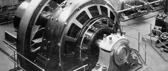
Among alternative energy sources, various types of electric current generators have become widespread. They are best suited for country houses and cottages, as well as other places where power outages often occur. In the event of a sudden loss of electricity, there is a need to quickly start a backup source in order to prevent disruption of the life support of the facility. Manual starting is quite complicated and requires special knowledge. Therefore, in such situations, as well as in the complete absence of people, the start function is performed automatically.
An automatic transfer switch for a generator, mounted on a special panel, is mainly used. This system allows you to turn on the unit and restore power supply in a matter of seconds. The working process involves two magnetic starters and a relay that controls the presence of voltage in the panel and the autostart system in the generator itself.
Connecting ATS
Before making the connection, it is necessary to correctly place all the parts in the electrical panel. They are installed in such a way that there are no crossings of conductors and free access to contacts and terminals is provided. After this, the power part of the ATS and controllers are connected in accordance with the circuit diagram.
Switching of the power part and controllers is carried out using contactors. After all connections, the ATS is directly connected to the generator. The correctness and quality of connections and connections of conductors and other elements is checked using a multimeter.
When using the normal mode, when the voltage is supplied from a regular power line, the automatic transmission system for the generator is activated in the ATS system and the first magnetic starter is turned on, supplying voltage to the switchboard of a private house. With the onset of emergency mode, in which there is no voltage in the network, a relay is used to turn off magnetic starter No. 1 and send a signal to the generator to perform autostart. After the generator starts operating in the ATS panel, the second magnetic starter is triggered, through which voltage begins to flow to the distribution panel of the home electrical network.
Operation in this mode will continue until the main supply of electricity appears or until the generator itself runs out of fuel. When the main voltage is turned on, the generator and magnetic starter No. 2 are turned off, and magnetic starter No. 1, on the contrary, is turned on, and the entire system returns to normal operation.
Installation of an automatic transfer switchboard is carried out after the electric meter. Thus, while the generator is operating, electricity consumption is not taken into account. In addition, the ATS shield for the generator is installed before the main switchboard of the home network. As a result, it ends up installed between the electricity meter and the distribution board.
If the total power of consumers available in the house exceeds the capabilities of the generator or the unit itself is not powerful enough, only those devices and equipment that are really necessary to ensure the normal functioning of the facility are connected to its line until the main power supply is turned on.
Classification ↑
AVR devices are divided into the following types:
- One-way work. In such a scheme there is one working and one reserve section of the supply electrical circuit.
- Double-sided work. Each supply line in such devices can be working and backup.
What are the requirements for ATS devices? ↑
- These devices must be turned on within the shortest possible time interval after the main power supply to the consumers is turned off.
- The ATS device must operate constantly, regardless of the reason for the power outage.
- The operation must occur once.
How to make your own AVR
Devices equipped with autostart are expensive, so it is recommended to assemble the ATS for the generator yourself, using the same elements as in factory models.
The main and most expensive part of the machine is the universal controller. Contactors are used as the power part, performing direct switching from the general network to the local network of the generator. To accommodate all the parts you will need a shield or cabinet that is most suitable in size for this device. The ATS circuit for the generator recommends using a special 1-3A control center as a power supply, and the switch should have three levels of operating modes. Electrical tools, cables and connectors should be prepared in advance.
To ensure high-quality assembly of the avr for the generator, it is necessary to follow certain recommendations and procedures. When choosing a controller yourself, you need to pay attention to the presence of an inverse air damper. This element is very useful for a generator equipped with a mechanical damper. When choosing contactors, you should focus on their throughput. If the device does not have electromechanical protection, it must be purchased separately.
In order to assemble an automatic transfer switch with your own hands, the circuit provides an automatic control device, which must have a normal constant voltage. The fulfillment of this condition is assigned to the power supply. Usually a high-power battery is used, since under heavy loads it discharges very quickly. This power supply regulates the output voltage. It is recommended to purchase all parts only from trusted specialized retail outlets, giving preference to products from the most well-known manufacturers.
Assembly begins with the installation of all parts and elements inside the electrical panel. Installation is carried out in such a way that there are no intersections of conductors with each other, and the contacts and terminals are accessible. For assembly, a diagram for connecting the ATS to the generator is used. After this, the controllers and power section are connected.
Serious attention should be paid to preventing parallel connection of the generator with the city electrical network. In this case, the unit may be seriously damaged, including complete failure. In order to avoid such negative consequences, it is recommended to use special switchboards that provide automatic or manual switching to automatic reserve input. These can be various types of high-current load switches or automatic generator voltage regulators.
When connecting, you need to take into account the presence of two cables included in the ATS shield. One of them belongs to the main network, and the other to the backup network. With different operating algorithms, they alternately switch. At the output, a single power cable is pulled to the consumers.
ATS circuit for 2 starters
The second scheme is a little more complicated. It already uses two magnetic starters.
Let's say you have two three-phase inputs and one consumer. The circuit uses magnetic starters with 4 contacts:
3 normally open
1 normally closed KM1
The starter coil KM1 is connected through phase L3 from the first input and through the normally closed contact KM2. So when you apply power to input #1, the coil of the first starter is closed and the entire load is connected to voltage source #1.
The second contactor is turned off, since the normally closed connector KM1 will be open at this moment, and power will not be supplied to the coil of the second starter. When the voltage disappears at the first input, contactor-1 disappears and contactor-2 turns on. The consumer remains with the light.
The main advantage of these schemes is their simplicity. The downside is that such assemblies can be called automation schemes with a very big stretch.
As soon as the voltage disappears in the phase that powers the switching coil, you can easily get a counter short circuit.
You can, of course, improve the entire system by choosing a contactor coil not for 220V, but for 380V. In this case, control will be carried out in two phases.
But you still won’t protect yourself 100%. And if you take into account the moment of possible sticking of contacts, then even more so.
In addition, you will not be protected in any way from too low voltage. Starter No. 1 can turn off only if U at the input is below 110V. In all other cases, your equipment will continue to receive low-quality electricity, although it would seem that there is a second serviceable input nearby.
To increase reliability, you will have to complicate the circuit and include additional elements in it:
voltage relay
phase control relay, etc.
Therefore, recently, to assemble ATS circuits, special relays or controllers—the “brains” of the entire device—have increasingly begun to be used. They can be from different manufacturers and perform the function of not only turning on backup power from one source.
Suddenly you are faced with a more difficult task. For example, it is necessary for the circuit to control two inputs at once and, in addition, a generator. Moreover, the generator should start automatically.
The working algorithm here is as follows:
1.If input No. 1 is faulty, automatic switching to input No. 2 occurs. 2. If there is no voltage at both inputs, the generator starts and the entire load is switched to it.
Characteristics of the Huter DY3000L gas generator
Here are briefly the parameters of this gasoline electric generator that interest us as electricians: Output power - 2000 VA (taking into account the power factor and reserve - we take 1.5 kW), start - manual. In principle, you don’t need to know anything more from the electrical side.
The remaining parameters of the generator can be found in the instructions.
The instructions for the generator, as well as something else, can be downloaded by reading the article to the end.
The main power consumers are the heating system (about 300 W, in winter it is the most strategically important consumer, for which the generator was bought), TV (100 W), refrigerator (300 W), lighting (300 W). Total - we fit perfectly into 1.5 kW. To power such a load, this generator is quite enough.
The house also has a 2.2 kW electric heater and a washing machine, but I was given my word of honor that they would not be powered by a generator.
Practical recommendations that have been confirmed in various projects
A guaranteed power supply system with a power of up to 100 kVA, which includes a UPS and operates from two network inputs.
In this case, automatic switches of the AK series, which are contactor-type automatic transfer switches, can be offered. These devices have:
This list of functionality allows you to successfully use AK series switches in systems containing UPS.
For such systems, it is more appropriate to use automatic switches of the AKP series, which are ATS on controlled switches with an electric drive.
These devices have all the features listed above, but in addition, they allow you to manually control input switching at any voltage or its absence
The switches are equipped with mechanical locks that allow them to be locked in any of the possible states, which may in some cases be important for the consumer
The following options for constructing an AVR can be proposed here:
Guaranteed power supply system
Three-input ATS schemes may be more economically attractive. At the same time, it should be noted again that for a three-input contactor circuit, full mechanical interlocking of all inputs with each other is impossible, which is determined by the design features of the contactors.
In this regard, in three-input contactor automatic transfer switches, it is advisable to install electrical and mechanical interlocking between the diesel generator and each of the network inputs. And between the network inputs, provide only electrical interlocking. It is on this principle that the three-input switches of the AK series are made.
The circuit of a three-input switch of the AKP series, as noted earlier, eliminates the possibility of shorting the inputs with each other due to the design of the switches and at the same time is cheaper than two separate cascade-connected ATS.
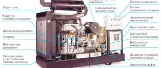
Generator design
The most important and capricious part of a Huter gasoline generator, like any other, is its starting system. The fuel valve, the air damper, the spark plug, the oil and gasoline levels - everything must be in the right position and normal.
What interests us is the engine operation switch (closed when turned off), AC and DC circuit breakers.
Below are a few photos of the electrical insides of the Huter 2500l generator:
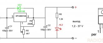
1_wiring diagram Huter DY3000L_diode bridge and voltmeter
We see a KBPC3510 diode bridge with 35 Amperes and 1000 Volts. With a declared charge current of no higher than 9A, a maximum voltage of 14V and a circuit breaker current of 10A, the diode bridge will work without problems.
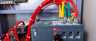
2_ wiring diagram of the Huter DY3000L gas generator _output terminals and protection
The second photo shows an alternating voltage circuit breaker, on which there is a sticker with information that its rated current is 12A, operation current is 15A. On the right is a 10A DC thermal relay.
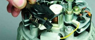
3_ wiring diagram Huter DY3000L _operation switch
The third photo shows the engine switch. I will use the wires to it to automatically stop the generator in the event of voltage coming from the city.
And the generator is turned on (started) manually, with the help of that puller, or, to put it correctly, a manual starter cable.
The model in question does not have autostart. X model has a battery-powered electric starter, where automatic starting is possible.
ATS with generator autostart
How will the generator start if the power from both inputs disappears? Contact No. 12 is used to connect an external +12V power supply to the ATS.
When you lose voltage on two inputs, all contacts K1, K2, K3 are in an open state. In this case, the internal contact of relay K4 automatically closes. Due to this, a start signal for the generator is generated.
Most generators with ATS capability control the damper with their own automation. To do this, they only need a start signal. You just serve it.
If you don’t have this, then you can make such a system yourself.
After the pulse is given, the diesel generator set starts and warms up. When it warms up, the voltage on relay KV1 reaches normal. KV1 is something like a three-phase motor protection relay.
It is necessary to control the voltage of a 3-phase network (correct phase rotation and their nominal value). For example, this would be suitable - CKF-317.
After operation, relay KV1 closes its contact KV1.1 and the voltage reaches connector No. 16. U also goes to pin No. 9 (it controls the internal circuits of the AVR) and No. 22.
AVR sees this and sends a signal to close relay K3 and coil KM3. After which the power contacts of the KM3.1 generator starter are turned on. The entire load is powered from the generator.
Huter gas generator diagram
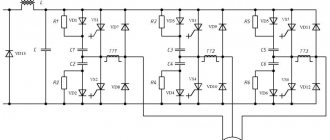
Let's look at the electrical circuit of the Huter DY 3000L gasoline generator, which I took from the instructions:
Electrical diagram of a single-phase gas generator Huter
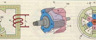
Briefly, how the gas generator circuit works. Alternator A2 is manually spun by a cable, ignition coil A5 produces a spark on spark plug F1, which starts the gasoline internal combustion engine. There will be no spark if switch SB1 is closed - the spark will be shorted to the housing.
What's new in the VK SamElectric.ru group?
Subscribe and read the article further:
Two output voltages of the alternator are generated - coil L1 220V (supplied through QF1 to the 220VAC output) and coil L2 - 12V (supplied to the output via the diode bridge and QF2). There is no direct current protection against short circuit; all hope for a short circuit is a large voltage drop.
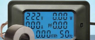
You can monitor the oil level using the HL1 indicator, and the voltage level using the PV1 dial gauge.
Coils L3 and L4 are responsible for the correct operation of the alternator and the stability of frequency and voltage.
System requirements
The main requirements for ATS systems are:
- Performance.
- Reliability of inclusion.
- Supply voltage only if there is no short circuit in the area, that is, there must be a blocking in the event of a short circuit.
- One-time operation.
- The ability to adjust the threshold for turning on the backup power supply so that it does not work, for example, during voltage sags during the start of powerful electric motors.
- Operation only if there is electricity at the backup input.
Naturally, the simplest circuit using contactors will not be able to implement all the requirements for the ATS system. For this purpose, modern electronics use logical systems that send a signal to turn on the backup power source only if all rules and interlocks are observed. Also, for additional reliability, a mechanical lock is even used.
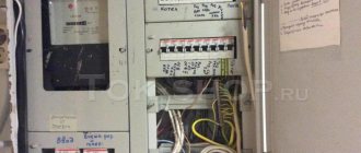
Installation
And here is the Huter dy3000l gasoline generator at its workplace:
7_Hooter generator, handsome, connected and installed
On the right there are two PVA wires - the generator output and the wire to the generator switch. On the left is grounding.
Huter DY3000L. General form
In this article I will consider in detail the design and electrical circuit of the Huter DY3000L gasoline generator. Generator without autostart. Photo of the generator is on the left.
This electric generator was purchased for backup power at the dacha, and about how I connected it, and what ATS circuits I considered, read - how I connected the Huter generator through an ATS.
And all my articles on generators are here.
AVR complies with the instructions of the PUE
According to the PUE, all consumers of electrical energy are divided into three categories:
- Category I—consumers in this group include those whose power supply disruption may result in danger to human life, significant material damage, a threat to state security, disruption of complex technological processes, etc.
- Category II - this group includes electrical receivers, a power interruption of which can lead to massive under-supply of products, downtime of workers, machinery, and industrial vehicles
- Category III—all other electricity consumers.
Characteristics of the Huter DY3000L gas generator
Here are briefly the parameters of this gasoline electric generator that interest us as electricians: Output power - 2000 VA (taking into account the power factor and reserve - we take 1.5 kW), start - manual. In principle, you don’t need to know anything more from the electrical side.
The remaining parameters of the generator can be found in the instructions.
The instructions for the generator, as well as something else, can be downloaded by reading the article to the end.
The main power consumers are the heating system (about 300 W, in winter it is the most strategically important consumer, for which the generator was bought), TV (100 W), refrigerator (300 W), lighting (300 W). Total - we fit perfectly into 1.5 kW. To power such a load, this generator is quite enough.
The house also has a 2.2 kW electric heater and a washing machine, but I was given my word of honor that they would not be powered by a generator.
Design and principle of operation
The ATS for the generator consists of three interconnected main blocks:
- families of contactors that switch input and load circuits;
- logical and indicating devices;
- block of relay switches designed to control the generator.
In order to increase the reliability of the backup power system, ATS devices can be equipped with additional units. For example, including inverters in a circuit allows you to level out voltage dips, eliminate time delays, and improve the output current.
The switching on of the backup line is ensured by the contact group. The presence of input voltage is monitored by a phase control relay.
Let's consider the principle of operation of the backup power system using the example of a simplified diagram (Fig. 2). In normal mode, when power is supplied from the main network, the contactor unit directs electricity to consumer lines. The diagram shows an additional unit - an inverter, which converts direct current from the battery into alternating current with a voltage of 220 V.
Rice. 2. Simplified backup power circuit
The signal about the presence of input voltage is sent to the block of logical and indicating devices. In nominal mode, the entire system is in a stable state. In the event of an accident in the main network (the voltage drops below the set level), the saturation of the phase control relay solenoid becomes insufficient to maintain the contacts in the operating (normally closed) state. The contacts are disconnected and the load is disconnected from the power line.
If the system is equipped with an inverter, as shown in the diagram, it switches to the mode of generating alternating current with a voltage of 220 V. Thus, consumers receive a stable voltage even in the complete absence of current in the commercial network.
If the parameters of the power lines are not restored within a specified period of time, the controller sends a signal to start the generator. When a stable voltage is received from the alternator, the contactors switch to the backup line.
Automatic switching on of the consumer network occurs as follows: the phase control relay receives voltage, switching the contactors to the main line. The backup power circuit is disconnected. The signal from the controller is sent to the fuel supply control mechanism, which closes the valve in a gasoline engine or shuts off diesel fuel in the diesel power system. The power plant shuts down.
With full automatic switching, operator intervention is not required. The system is reliably protected from the interaction of counter currents and short circuits. For this, additional relays and interlocking mechanisms are used, which are not shown in the diagram.
If necessary, the operator can switch lines manually from the controller panel. It can also change the settings of the control unit, enable manual or automatic operating mode. A photo of the panel is shown in Fig. 3.
Rice. 3. Backup power controller panel
Several operating modes can be implemented in the ATS:
- manual;
- auto;
- semi-automatic.
The manual mode is most often used by service technicians when setting up ATS.
Huter gas generator diagram
Let's look at the electrical circuit of the Huter DY 3000L gasoline generator, which I took from the instructions:
Electrical diagram of a single-phase gas generator Huter
Briefly, how the gas generator circuit works. Alternator A2 is manually spun by a cable, ignition coil A5 produces a spark on spark plug F1, which starts the gasoline internal combustion engine. There will be no spark if switch SB1 is closed - the spark will be shorted to the housing.
What's new in the VK SamElectric.ru group?
Subscribe and read the article further:
Two output voltages of the alternator are generated - coil L1 220V (supplied through QF1 to the 220VAC output) and coil L2 - 12V (supplied to the output via the diode bridge and QF2). There is no direct current protection against short circuit; all hope for a short circuit is a large voltage drop.
You can monitor the oil level using the HL1 indicator, and the voltage level using the PV1 dial gauge.
Coils L3 and L4 are responsible for the correct operation of the alternator and the stability of frequency and voltage.