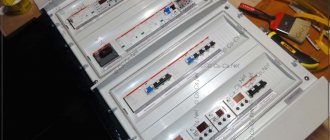
Marking is a system of symbols intended for application to wires, circuits, secondary devices and their circuits.
It is performed with the aim of accurately drawing electrical circuits, quickly identifying individual elements and ease of use. Marking is carried out on all panels that contain secondary circuits, devices, control cable cores, and the cables themselves. The regulatory document on the basis of which marking is carried out is the Guidelines of the USSR Ministry of Energy 10260TM-T1, put into effect on April 1, 1981.
Marking of DC electrical circuits is carried out with digital symbols taking into account polarity. The part of the circuit with positive polarity is marked with odd numbers, and the negative part with even numbers.
Sections of secondary circuits that do not have constant polarity can be designated by even and odd numbers.
The numbers used to mark secondary circuits are divided into hundreds (one group is 1 - 99, another - 101 - 199, etc.). If the main numbering is insufficient, an additional four-digit number is used, with a digit added in front of the main one.
Watch an interesting video about marking circuits below:
Most often in the diagrams you can find the following circuit markings:
1 – “positive” nutrition;
2 – "negative" nutrition;
3 – 19 (usually 3 is used) – switching circuits;
20 – 29 – circuits of current relay coils.
Sometimes a letter is placed in front of the number; this marking is mainly used for circuits for a specific purpose, for example:
P – used when designating breaker failure circuits;
U – communication circuits;
T – telemechanics circuits.
Table of distribution of numbers for marking circuits
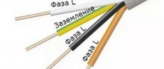
The designation of alternating current circuits is usually done in serial numbers, with the addition of a letter designation of the phase or neutral of the circuit (A, B, C, N) in front: N1 - N99; A1 – A99, etc.
The letter designation may not be used unless precise phase evidence is required.
Letter distribution table for circuit markings
Voltage transformer
Author: Vladimir Vasiliev · Published January 20, 2016 · Updated August 29, 2018
The transformer owes its appearance to the English scientist Michael Faraday. In 1831, a physicist described a phenomenon he called “electromagnetic induction.” It lies in the fact that in closely spaced coils (windings) a pronounced
electromagnetic coupling. That is, if an alternating current is created in the first coil (primary winding), then a voltage with a similar frequency and power is excited in the second coil (secondary winding), depending on many parameters, which we will consider later.
What does a transformer consist of?
The basis of each transformer is a closed core that performs the function of a magnetic circuit. For its manufacture, electrical steel is used in the form of sheets with a thickness of 0.35 - 0.5 mm. Insulated copper wires are wound onto the magnetic circuit.
The sections of the core with windings are called rods, and those without windings are called yokes. The winding to which electricity is supplied is called the primary winding. The other winding from which the converted current comes out is called the secondary winding. They are both separated from each other by electrical isolation, except for automatic transformers.
Voltage transformers purpose and principle of operation
Voltage transformers are designed to convert the energy of a voltage source into a voltage with the desired value (amplitude). It should be noted that such transformers work only with alternating voltage and its frequency remains unchanged.
Why do you need a voltage transformer?
Voltage transformers, due to their versatility, are needed in power supplies, signal processing devices, transmission devices, power transmission devices and many other equipment.
Based on the transformation ratio, these devices can be divided into 3 types:
- step-down voltage transformer – the device output voltage is lower than the input voltage (n>1), for example, used in power supplies;
- step-up transformer - the output voltage of the device is higher than the voltage at the input (n How does a voltage transformer work?
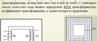
After an alternating voltage U1 appears in the primary winding, an alternating magnetic flux Ф appears in the magnetic circuit, which excites voltage in the secondary winding U2. This is the simplest and most concise description of the operating principle of a voltage transformer.
The most important parameter of transformers is the “transformation ratio” and is denoted by the Latin “n”. It is calculated by dividing the voltage in the primary winding by the voltage in the secondary winding or the number of turns in the first coil by the number of turns in the second coil.
This coefficient allows you to calculate the required parameters of your transformer for the selected device. For example, if the primary winding has 2000 turns and the secondary winding has 100 turns, then n=20. With a network voltage of 240 volts, the output of the device should be 12 volts. You can also determine the number of turns at given input and output voltages.
Transformers - purpose, types and characteristics
To bookmarks
Introduction
A transformer is a static device having two or more windings, designed to convert, by electromagnetic induction, one or more alternating voltage and current systems into one or more other alternating voltage and current systems, usually having different values at the same frequency, for the purpose of transmitting power . (Source: GOST 30830-2002)
Fig.1 General view of the transformer
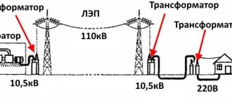
The importance of transformers both in the electric power industry in general and in the everyday life of every person can hardly be overestimated; they are used everywhere: at substations, in cities and towns, there are power transformers that lower high voltages of thousands and even tens of thousands of volts to the usual 380/220. Volt, enterprises have welding transformers that are absolutely indispensable in production; transformers are also used at home in household appliances: in microwave ovens, computer power supplies and even phone chargers.
In this article we will understand how transformers are structured and how they work, what types of transformers there are, and also give their general characteristics.
General structure and principle of operation of transformers
In general, a transformer consists of two windings located on a common magnetic circuit. The windings are made of copper or aluminum wire in enamel insulation, and the magnetic core is made of thin varnish-insulated electrical steel plates to reduce electricity losses due to eddy currents (the so-called Foucault currents).
The winding that is connected to the power source is called the primary winding, and the winding to which the load is connected is called the secondary winding. If a voltage (U2) is removed from the secondary winding (W2) of a transformer lower than the voltage (U1) supplied to the primary winding (W1), then such a transformer is considered a step-down transformer, and if higher, it is considered a step-up transformer.
Fig. 2 Diagram of the general structure of the transformer
The metal part on which the electrical winding (coil) is located, i.e. which is located in its center is called a core, in transformers this core has a closed design and is common to all windings of the transformer, such a core is called a magnetic circuit.
As mentioned above, the operating principle of transformers is based on the law of electromagnetic induction; to understand how this works, let’s imagine the simplest transformer, similar to the one shown in Figure 2, i.e. we have a magnetic circuit on which there are 2 windings, imagine that the first winding consists of only one turn, and the second - of two.
Now let’s apply a voltage of 1 Volt to the first winding, its only turn will conditionally create a magnetic flux of 1 Wb (For reference: Weber (Wb) is a unit of measurement of magnetic flux) in the magnetic core, since the magnetic core has a closed design; the magnetic flux will flow in it in a circle while crossing 2 turns of the second winding, in each of these turns, due to electromagnetic induction, it induces (induces) an electromotive force (EMF) of 1 Volt, the EMF of these two turns adds up and at the output from the second winding we get 2 Volts.
Thus, by applying 1 Volt to the primary winding, we received 2 Volts on the secondary winding, i.e. in this case, the transformer will be called a step-up transformer, because it increases the voltage applied to it.
But this transformer can also work in the opposite direction, i.e. if 2 Volts are applied to the second winding (with two turns), then from the first winding according to the same principle we will receive 1 Volt, in this case the transformer will be called a step-down transformer.
General characteristics of transformers
The main technical characteristics of transformers include:
- rated power;
- rated voltage of windings;
- rated current of windings;
- transformation ratio;
- efficiency;
- number of windings;
- operating frequency;
- number of phases.
Power is one of the main parameters of transformers. The passport (factory) data of the transformer indicates its total power (indicated by the letter S), it depends on the type of magnetic circuit used, the number and diameter of turns in the windings, that is, on the weight and dimensions of the electromagnetic device.
Power is measured in units of VA (Volt-Ampere). In practice, for high-power transformers, as a rule, multiples of Volt-Amps are used: Kilovolt-ampere - kVA (103 VA∙A) and Megavolt-ampere - MVA (106 VA∙A).
In fact, each transformer has 2 power values: input (S1) - the power that the transformer consumes from the network supplying it and output (S2) - the power that the transformer gives to the load connected to it, while the output power is always less than the input due to electrical losses in in the transformer itself (winding heating losses, eddy current losses, etc.), the magnitude of these losses is determined by another main parameter - the coefficient of performance, abbreviated as efficiency (denoted by the letter η), this parameter is indicated as a percentage.
For example, if the efficiency is specified as 92%, this means that the output power of the transformer will be 8% less than the input power, i.e. 8% is the loss in the transformer.
Power calculation formulas:
- Input power: S1=U1x I1 ,VA;
- Output power: S2=U2x I2 ,VA;
Where:
- I1, I2 - respectively, currents in the primary and secondary windings of the transformer in Amperes;
- U1, U2 - respectively, the voltages of the primary and secondary windings of the transformer in Volts.
It should be remembered that total power consists of active (P) and reactive (Q) powers:
- Active power is determined by the formula: P=U x I x cosφ , Watt (W)
- Reactive power is determined by the formula: Q=U x I x sinφ , volt-ampere reactive (Var)
- Power factor: cosφ=P/S;
- Reactive power factor: sinφ =Q/S
Formulas for calculating the efficiency (η) of a transformer:
As already mentioned above, the efficiency determines the amount of losses in the transformer or, in other words, the operating efficiency of the transformer and is determined by the ratio of the output power ( P2 ) to the input power ( P1 ):
η=P2/P1
As a result of this calculation, the efficiency value is determined in relative units (in the form of a decimal fraction), for example - 0.92, in order to obtain the efficiency value as a percentage, the calculated value must be multiplied by 100% (0.92*100%=92%).
The closer the efficiency is to 100%, the better, i.e. an ideal transformer is a transformer in which P2=P1 , but in reality, due to losses in the transformer, the output power is always lower than the input power.
This can be clearly seen from the so-called energy diagram of the transformer (Fig. 3):
- P1 is the active power consumed by the transformer from the source;
- P2 - active (useful) power supplied by the transformer to the receiver;
- ∆Pel - electrical losses in the transformer windings;
- ∆Рм — magnetic losses in the magnetic core of the transformer;
- ∆Рdop - additional losses in other structural elements.
In the no-load mode (operation without a load connected to the transformer), the efficiency of the transformer is η = 0. The no-load power P0 consumed by the transformer in this mode is spent on compensating for magnetic losses. With increasing load in a fairly small range (approximately β = 0.2), the efficiency reaches large values. In the rest of the operating range, the efficiency of the transformer remains at a high level. In modes close to the nominal one, the efficiency of the transformer is η nom = 0.9 - 0.98.
The dependence of efficiency on load is presented in the following graph (Fig. 4):
The primary rated voltage U1n is the voltage that must be applied to the primary coil of the transformer in order to obtain the rated secondary voltage U2n in no-load mode.
The secondary rated voltage U2н is the value that is set at the terminals of the secondary winding when the rated primary voltage U1н is applied to the primary winding in no-load mode.
Rated primary current I1н is the maximum current flowing in the primary winding, i.e. consumed by the transformer from the network for which this transformer is designed and at which its long-term operation is possible.
The rated secondary current I2n is the maximum load current flowing in the secondary winding for which this transformer is designed and at which its long-term operation is possible.
Transformation ratio ( kt) is the ratio of the number of turns in the primary winding to the number of turns in the secondary winding k=W1/W2.
Also kt is defined as the ratio of voltages at the winding terminals: kt = U1n/U2n.
For a step-down transformer, the transformation ratio is greater than 1, and for a step-up transformer, it is less than 1.
Note: for current transformers kt is defined as the ratio of the rated values of the primary and secondary currents kt = I1n/I2n
The number of windings for single-phase transformers is usually two, but can be more. One voltage value is applied to the primary winding, and another value is removed from the secondary winding.
When different voltages are required to power several devices, then in this case there may be several secondary windings. There are also transformers with a common point on the secondary winding for bipolar power supply.
The operating frequency of transformers may vary. But with the same primary winding voltages, a transformer designed for a frequency of 50 Hz can be used at a mains frequency of 60 Hz, but not vice versa. At a frequency lower than the nominal one, the induction in the magnetic circuit increases, which can lead to its saturation and, as a consequence, a sharp increase in the no-load current and a change in its shape. At a frequency higher than the rated one , the magnitude of parasitic currents in the magnetic core increases, the heating of the magnetic core and windings increases, leading to accelerated aging and destruction of the insulation.
The dimensions of the transformer directly depend on the frequency of the current in the circuit in which it will be installed. Of course, the transformer must be designed for this frequency. This dependence is inverse, i.e. As the frequency increases, the dimensions of the transformer decrease significantly. That is why switching power supplies (with pulsed high-frequency transformers) are much more compact.
Depending on the purpose, transformers are made single-phase and three-phase.
A single-phase transformer is a device for transforming electrical energy in a single-phase circuit. Basically it has two windings, primary and secondary, but there can be several secondary windings.
A three-phase transformer is a device for transforming electrical energy in a three-phase circuit. Structurally, it consists of three magnetic cores connected by an upper and lower yoke. Each rod is equipped with windings W1 and W2 of the highest (U1) and low (U2) voltages of each phase (Fig. 5).
Types of transformers
All transformers can be divided into the following types:
- power;
- autotransformers;
- measuring;
- dividing;
- coordinating;
- pulse;
- peak transformers;
- welding
Power transformers are the most common type of industrial transformer. They are used to increase or decrease voltage. They are an integral part of the power supply network for enterprises, settlements, etc.
An autotransformer is a transformer that has only one winding with the number of turns W1. Part of this winding with the number of turns W2 belongs simultaneously to the primary and secondary circuits:
This type of transformers is used in automatic voltage regulation devices. These devices are used, for example, in educational institutions for carrying out laboratory work; they can be found in electrical laboratories of various enterprises for carrying out test work.
Appearance of autotransformers:
Instrument transformers are divided into voltage transformers and current transformers. They provide galvanic isolation between high and low voltage circuits. As the name suggests, the main application is to reduce the primary voltage or current to a value used in measuring circuits, for example for connecting ammeters, voltmeters, and electricity meters. They can also be used in various protection, control and signaling circuits. They differ from other types of transformers by increased accuracy and stability of the transformation ratio.
Example of instrument transformers:
→ Read more about instrument transformers here.
Isolation transformers , these devices are not much different from conventional step-down or step-up transformers. The only difference is that absolutely identical windings are placed on a common magnetic core. That is, they completely match such parameters as wire cross-section, number of turns, insulation. Therefore, their transformation coefficient is equal to one.
The task of these devices is to provide galvanic isolation, i.e. exclusion of direct electrical connection between the electrical network and the equipment connected to it through this transformer.
They are used in areas where there are increased requirements for electrical safety, such as connecting medical equipment.
Matching transformers are used to match the resistance of various parts of cascades of electronic circuits, as well as to connect a load that does not correspond in resistance to the permissible values of the signal source, which makes it possible to transfer maximum power to such a load. In this case, the direct change in current and voltage indicators does not matter.
They are used in low-frequency amplifiers as input, interstage and output transformers.
As input, matching transformers are used in sound-reproducing equipment to connect microphones and sound pickups of various types.
Transformers of this type are used to match the signal when connecting antennas to receiving and transmitting devices.
Pulse transformers are devices with a ferromagnetic core that are used to change pulses of current or voltage. Convert the received signal into a rectangular pulse. Used to prevent high frequency interference. Pulse transformers are most often used in electronic computing devices, radar systems, pulse radio communications, and as measuring devices in electricity meters
Peak transformers - convert sinusoidal voltage into pulse peaks while maintaining their polarity and oscillation frequency.
Indispensable where starting the actuator requires a single pulse with a set voltage amplitude. These are, for example, control electronic circuits assembled using thyristors. They are also used as pulse generators, mainly in high-voltage research facilities, communications and radar technology. Peak transformers are most widely used in process automation.
Welding transformers are the main power sources for manual arc welding on alternating current. They serve to reduce the network voltage from 220V or 380V to a safe one and at the same time increase the current value to increase the temperature of the electric arc.
→ Read more about welding transformers here.
Was this article useful to you? Or maybe you still have questions ? Write in the comments!
Didn’t find an article on the website on a topic that interests you regarding electrical engineering? Write to us here. We will definitely answer you.
↑ Up
0
https://elektroshkola.ru/transformatory/transformatory-naznachenie-vidy-i-xarakteristiki/
Additional Information
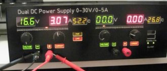
Before buying a voltage transformer, you need to analyze all the requirements for the device. It is necessary to take into account not only operating voltages, but also load currents when using a transformer in various devices.
You can make voltage transformers yourself, but if you need a simple household transformer with a voltage of 220 volts and a step down to 12 volts, then it is better to purchase one. You can find out how much voltage transformers cost on any website; as a rule, prices for household step-down voltage transformers are not very high.
Connection diagrams
Connection diagrams for single-phase voltage transformers:
Connection diagrams for three-phase voltage transformers:
Diagrams and groups of connections of windings of three-phase three-winding transformers with main and additional secondary windings
Also read: Isolation transformer
Voltage transformers - purpose and principle of operation
They are found wherever there is a need to convert high network voltage to a proportionally lower value. This is their purpose: transforming the magnitude of voltage. TNs are used for:
- reducing the voltage to a value that is safe and convenient to use in measurement circuits (voltmeters, wattmeters, meters), protection, automation, alarms
- protection from high voltage of secondary circuits, and therefore of humans
- increase in voltage when testing insulation of various EOs
- at substations, VTs are used to monitor network insulation, work as part of an alarm device or protect against ground faults
If there were no voltage transformers, then, for example, to measure the voltage on a 10 kV bus, you would have to build a super-powerful voltmeter with insulation that can withstand 10 kV. And these are wow dimensions. And another plus to this is the need to maintain the accuracy of measurements. It's a problem, but that's not all. If something shorts in such a device, then the electrician makes a mistake... when choosing a profession. 10 kV, but there is also 750 kV, how to measure there? The catch. Therefore, we salute the inventors of transformers, and in particular voltage transformers. We're distracted, let's continue.
Before moving on, I will draw a single-phase VT to make it clearer and more understandable later in the presentation of the material.
This means that in the figure above we have voltage coming to terminals A, X of the voltage transformer to the primary winding (1). This voltage is the nominal voltage, the primary voltage. Next, it is transformed to the value of the secondary voltage, which is located on the secondary winding (3). Conclusions of the secondary winding - a, x. The output of the secondary winding is grounded. B is a voltmeter, but it could be another device. (2) is the magnetic circuit of the TN.
Ideal Transformer Equations
In such a transformer, power lines pass through all branches of the primary and secondary windings. This means that there are no vortex flows and energy losses. The magnetic field changes, but generates an identical EMF in all turns, and therefore becomes directly proportional to their total number.
When energy comes from the primary circuit, it is transformed into a magnetic field and then enters the secondary circuit.
The formula for the ideal transformer equation is P1 = I1 • U1 = P2 = I2 • U2:
- R1 is the coefficient of incoming power from the first circuit to the transformer;
- R2 is the coefficient of converted power entering the secondary circuit.
If you increase the voltage at the ends of the secondary winding, the current level of the primary circuit will decrease. According to the equation - U2/U1 = N2/N1 = I1/I2, converting the resistance of one circuit to the resistance of another is possible only by multiplying the value by the square of the ratio.
Operating principle of TN
The operating principle of a voltage transformer is similar to that of a current transformer. Let's define this again. An alternating current passes through the primary winding, this current forms a magnetic flux. The magnetic flux penetrates the magnetic circuit and the HV and LV windings. If a load is connected to the secondary winding, then a current begins to flow through it, which arises due to the action of the EMF. EMF is induced due to the action of magnetic flux. By selecting different numbers of turns of the primary and secondary windings, you can obtain the desired output voltage. This is shown in more detail in the article about the vector diagram of a voltage transformer.
If a constant voltage is applied to the VT, then the EMF is not created by the constant magnetic flux. Therefore, VTs are produced for alternating voltage. The transformation ratio of a voltage transformer is naturally called the ratio of the voltage of the primary winding to the voltage of the secondary and is written as a fraction. For example, 6000/100. When young students come, they sometimes answer the question of what coefficient is 60. You shouldn’t do that.
Faraday's law
According to the law of electromagnetic induction, an EMF voltage is created in the secondary winding. Calculated by the formula - U2 = −N2*dΦ/dt.
Reference! Faraday's fundamental law of electrodynamics. It states that the generated electromotive force is equal to the rate of change of magnetic flux, but taken with a minus sign. It was Michael Faraday who made the discovery when, during experiments, he announced that electromotive force begins to appear in a conductor only when the magnetic field changes. The magnitude of this force is directly proportional to the rate of change of the magnetic field.
All the facts are contained in one equation. However, the minus sign in the law is Lenz’s rule, which indicates the occurrence of an inductive electric current when the magnetic field in the conductor changes. The action of the current is directed towards the magnetic field, which begins to counteract the change in magnetic flux.
Lenz's rule does not obey the laws of electrodynamics, because induction current appears both in windings and in solid metal blocks.
Classification of voltage transformers
TNs are classified according to the following parameters:
- primary winding voltage (3, 6, 10 ... 750 kV)
- voltage of the main secondary winding (100 V - for single-phase, connected between phases, three-phase; 100√3 - single-phase, connected between phase and ground voltage of the additional secondary winding (100V - single-phase in a network with a grounded neutral, 100√3 - single-phase in a network with isolated neutral
- number of phases (single-phase, three-phase)
- number of windings (two-winding, three-winding)
- accuracy class (0.1 0.2 0.5 1 3 3Р 6Р)
- cooling method (dry, oil, gas-filled)
- insulation (air-paper, cast, compound, gas, oil, porcelain)
For voltages of 6 and 10 kV, cast transformer transformers filled with epoxy resin are used. These devices are installed in switchgears. They take up smaller dimensions compared to oil ones. Their advantages also include less maintenance.
electromagnetic and capacitive
If you open the volumes and standards of testing electrical equipment on the TNov page, you can see that voltage transformers there are divided into electromagnetic and capacitive. What is the difference between these types of equipment?
We consider all HPs in which the transformation occurs according to the principle described above (magnetic fluxes, EMF, and so on) to be electromagnetic. Induction current, in the brochures of Western manufacturers they are called inductive, as opposed to capacitive. In my opinion, everything is exactly like that.
But capacitive voltage transformers, or capacitive voltage dividers... Here history is silent. The operating principle of such equipment can be understood by drawing a diagram.
Here, for example, is a diagram of a fuel pump of the NDE-M brand. They are produced for voltages above 110 kV. Consists of a capacitive divider and an electromagnetic device. The capacitive divider consists of capacitors C1 and C2. The principle of a capacitive divider is as follows. The voltage of line A is divided in inverse proportion to the values of capacitors C1 and C2. That is, we connect our TN to C2 and the voltage on it is proportional to the input, which goes along L, but is much less than it. Since we are considering NDE, here is a table of voltage values for different classes of equipment.
The electromagnetic device consists of a step-down transformer, a reactor and a damper.
The reactor is designed to compensate for capacitance and therefore reduce the error.
The electromagnetic damper is designed to eliminate subharmonic oscillations that can occur during switching on and short circuits in the windings of the transformer.
The higher the voltage class, the more profitable capacitive voltage transformers are than their counterparts. By reducing the size of insulation and materials.
Bookmark or share with friends
Measuring voltage transformers. Design, classification, principle of operation, examples
A voltage transformer is one of the types of transformers, which is also called a measuring transformer, designed to separate the primary circuits of high and ultra-high voltages and measurement circuits, relay protection and A. They are also used to reduce high voltages (110, 10 and 6 kV) to standard rated ones voltage values of the secondary windings – 100 or 100/√3.
In addition, the use of voltage transformers in electrical installations makes it possible to isolate low-power, low-voltage measuring instruments and devices, which reduces the cost and allows the use of simpler equipment, and also ensures the safety of servicing electrical installations.
Voltage transformers are widely used in high voltage power electrical installations
The accuracy of commercial metering of electricity, the selectivity of the action of relay protection and emergency automation devices depend on the accuracy of their operation, they also serve to synchronize and power automatic relay protection of power lines from short circuits, etc.
Such transformers are equipped with connectors for connection: the primary winding is connected to power voltage circuits, and relays, voltmeter or wattmeter windings, and other devices can be connected to the secondary winding. Their operating principle is similar to that of a power transformer: the voltage in the measuring transformer is transformed by an alternating magnetic field.
For an interesting video about the operation and design principle of current transformers, see below:
Magnetization losses cause some error in accuracy classes.
- magnetic circuit design;
- permeability of steel;
- power factor, i.e. depends on the secondary load.
The design provides compensation for voltage errors by reducing the number of turns of the primary winding and eliminating angular errors using compensating windings. The simplest circuit for connecting a voltage transformer
Three-phase transformer
Among the electromagnetic devices of this type, the three-phase transformer stands out. It has magnetic and galvanic phase connections. The presence of a circuit of the first type is due to the connection of magnetic circuits into one system. In this case, the magnetic fluxes are located relative to each other at an angle of 120 °. A rod is not needed in this system, since when the centers of the three phases are combined, the sum of the electromagnetic channels is equal to zero, regardless of time. Thanks to this, a circuit with six rods is converted into a three-rod one.
Three types of circuits can be used to connect the windings of the device:
- A star connection can be made with or without output from common points. Here each winding is connected to a neutral point.
- According to a triangular diagram, the phases are connected in series.
- Zigzag is a pattern that is most often used during retraction from a common point. It connects three windings located on different magnetic cores.
The use of a three-phase transformer is more economical than the use of connected single-phase structures.
Voltage transformer load
The secondary load of the voltage transformer is the power of the external secondary circuit. The rated secondary load is understood as the highest load at which the error does not exceed the permissible limits established for transformers of a given accuracy class.
Voltage transformer designs
In installations with voltages up to 18 kV, three-phase and single-phase transformers are used; at higher voltages, only single-phase transformers are used.
At voltages up to 20 kV there are a large number of types of voltage transformers: dry (NOS), oil (NOM, ZNOM, NTMI , NTMK), with cast insulation ( ZNOL ). It is necessary to distinguish single-phase two-winding transformers NOM from single-phase three-winding transformers ZNOM. Transformers of types ZNOM-15, -20 -24 and ZNOL-06 are installed in complete conductors of powerful generators. In installations with voltages of 110 kV and higher, cascade-type voltage transformers NKF and capacitive voltage dividers NDE are used.
Voltage transformers
Instrument voltage transformers are designed to reduce primary voltages to values that are most convenient for connecting measuring instruments, protection relays, and automation devices. The use of instrument transformers ensures the safety of workers, since the high and low voltage circuits are separated, and also makes it possible to unify the design of devices and relays.
What is the difference between a current transformer and a voltage transformer?
By definition, these devices are designed to work with different electrical quantities as basic ones and, accordingly, the switching circuits will be different. For example, a current transformer is powered by a current source and does not work, and may even fail, if its windings are not loaded and no electric current flows through them. The voltage transformer is powered by voltage sources and, conversely, cannot operate for a long time in modes with high current loads
Video: Voltage Transformers
Technical characteristics of voltage transformers, connection diagrams. Factors influencing the accuracy class. Types of voltage transformers, identification of markings.
What is a voltage transformer
Classification of voltage transformers
- By number of phases:
- single-phase;
- three-phase.
- By number of windings:
- 2-winding;
- 3-winding.
- According to the method of operation of the cooling system:
- oil-cooled electrical devices;
- electrical devices with an air cooling system (cast insulation or dry).
- By installation and placement method:
- for outdoor installation;
- for internal;
- for complete switchgear.
- By accuracy class: by standardized error values.
Types of voltage transformers
Let's look at several voltage transformers from different manufacturers:
Voltage transformer ZNOL-NTZ-35-IV-11
Manufacturer: Nevsky Transformer.
Purpose and scope of application ZNOL-NTZ
Transformers are designed for outdoor installation in open switchgears (OSD). Transformers provide signal transmission of measuring information to measuring instruments, protection and control devices, and are intended for use in commercial electricity metering circuits in AC electrical installations for a voltage class of 35 kV. Transformers are made in the form of a supporting structure.
The transformer housing is made of a compound based on hydrophobic cycloaliphatic resin “Huntsman”, which at the same time serves as the main insulation and provides protection of the windings from mechanical and climatic influences. The operating position of the transformers in space is vertical, with high-voltage leads up.
Figure - Overall dimensions of the transformer
Figure - transformer winding connection diagrams
Characteristics:
- Voltage class according to GOST 1516.3, kV - 27 35 27
- Maximum operating voltage, kV - 30 40.5 40.5
- Rated voltage of the primary winding, kV - 15.6 20.2 27.5
- Rated voltage of the main secondary winding, V - 57.7 100
- Rated voltage of the additional secondary winding, V - 100/3, 100 127
- Nominal accuracy classes of the main secondary winding are 0.2; 0.5; 1; 3
Another interesting video about the operation of current transformers:
Three-phase anti-resonance group of voltage transformers 3xZNOLPM(I)
Purpose of 3xZNOLPM(I)
Transformers are designed for installation in complete devices (switchgear), conductors and serve to power measurement, protection, automation, alarm and control circuits in electrical installations of alternating current frequency 50 or 60 Hz in networks with an isolated neutral.
Transformers are manufactured in the “UHL” climatic design, placement category 2 according to GOST 15150.
Working position - any.
The location of the primary output is possible both on the front and on the rear side of the transformer.
The three-phase group can be equipped in 4 options:
- of three transformers ZNOLPM - 3xZNOLPM-6 and 3xZNOLPM-10;
- of three ZNOLPMI transformers - 3xZNOLPMI-6 and 3xZNOLPMI-10;
- from one transformer ZNOLPM (installed in the middle) and two transformers ZNOLPMI (installed at the edges) - 3xZNOLPM(1)-6 and 3xZNOLPM(1)-10;
- of two transformers ZNOLPM (installed at the edges) and one transformer ZNOLPMI (installed in the middle) - 3xZNOLPM(2)-6 and 3xZNOLPM(2)-10.
To increase resistance to ferroresonance and the effects of intermittent arcs, it is recommended to include a 25 Ohm resistor designed for a long-term flow of 4A current in the additional windings connected in an open delta used to control the network insulation.
Attention! When ordering voltage transformers for AISKUE, it is necessary to fill out a questionnaire.
The warranty period is 5 (five) years from the date of commissioning of the transformer, but not more than 5.5 years from the date of shipment from the manufacturer.
Service life - 30 years.
NAMIT-10-2
Purpose and scope
The NAMIT-10-2 UHL2 three-phase oil anti-resonance voltage transformer is a large-scale converter and is designed to generate a measurement information signal for measuring instruments in metering, protection and signaling circuits in 6 and 10 kV AC networks of industrial frequency with an isolated neutral or grounded through an arc suppression reactor. The transformer is installed in switchgear cabinets (N) and in closed switchgear of industrial enterprises
Technical parameters of voltage transformer NAMIT-10-2
- Rated voltage of the primary winding, kV - 6 or 10
- Highest operating voltage, kV - 7.2 or 12
- Rated voltage of the main secondary winding (between phases), V - 100 (110)
- Voltage of the additional secondary winding (aD - xD), no more, V - 3
- Accuracy class of the main secondary winding - 0.2/0.5
Figure - Dimensions and connection diagram
{SOURCE}