When making homemade power supplies or chargers, craftsmen often equip such devices with digital voltammeters. The price of such devices fluctuates around a few dollars, and their accuracy allows you to completely forget about dial gauges. Given the wide range of modern voltammeters, you may encounter problems connecting them. Today our article is devoted to the most popular voltammeters and their connection diagrams. Also, in addition to the standard circuit, we will describe how to connect a voltammeter to a charger
Contents
The current consumed by the voltmeter was about 15 mA and varied depending on the number of illuminated segments.
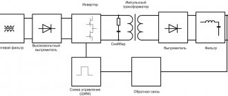
When the output voltage is more than 12V, the LCV voltage stabilizer comes into operation and thereby maintains a constant voltage on the fan of no more than 12V. It needs to be done with a thicker wire. An AC voltmeter shows the actual voltage value. Circuit diagram for connecting a voltmeter with additional resistances. The measurement limit is increased by connecting in series with an additional resistance device Rext.
Diagram for connecting a voltmeter-ampmeter to an adjustable power supply. At the bottom of the circuit, the fan and the Chinese voltmeter-ampmeter are connected through an LCV voltage stabilizer to the output of the diode bridge in parallel with capacitor C1. In my opinion, the body of the device is a little small - the LED matrices fit closely to the inside of the body and when installing the module in the front panel of the devices, the clamps are left with no room for maneuver. Let's take a closer look at the two models of the most popular voltmeters and ammeters made in China. Contacts How to connect a voltmeter-ampmeter Very often, beginning radio amateurs ask the same question: - How to connect a universal Chinese voltmeter-ampmeter to a homemade charger or an regulated power supply?
Comments
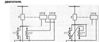
This figure shows a diagram of connecting a Chinese voltmeter-ampmeter of the second model to an adjustable power supply.
To connect the load, I recommend using the same one. Measured voltage V; current A. Since the electronic filling of the ampere-voltmeter is powered by a voltage of 4 volts, there are two connection methods: 1. Unsoldered the indicator, drew a diagram; the numbering of parts is shown conventionally: Unfortunately, the chip remained unidentified - there is no marking. Diagram for connecting a voltmeter, ammeter, and fan to a charger from a computer power supply. Download a diagram for connecting a voltmeter, ammeter, and fan to a charger. The device is powered from a separate power source; in this case, it is a five-volt charger from a phone, which can be easily placed in the power supply case. This coil is located on the same axis with a permanent magnet in devices used in direct current networks, or with another coil in alternating voltage devices.
Chinese voltammeter dsn-vc The first one on the left has three thick wires black, blue, red and two thin wires black, red. I supplied a maximum of 56V - I don’t have any more, nothing burned out :-, but the error also increased. In principle, you can now find it cheaper if you look hard enough, but it’s not a fact that this will not be to the detriment of the build quality of the device. How to connect a digital volt-ampere meter from China
Determination of electricity losses in 10(6) kV networks
16.1. The initial data for calculating electrical energy losses in a 10(6) kV network are:
total amount of active electricity W
p(kWh) supplied to the distribution network during the billing period;
amount of active W
A(kWh) and reactive
W
р(kVAr∙h) energy supplied to each line with a voltage of 10(6) kV during the billing period;
daily hourly load graphs I
(
t
) (A) on CPU buses for working days of winter maximum and summer minimum loads, selected for control measurements during the calculation period;
information on the duration of line outages during the billing period, hours;
data on the actual amount of electrical energy consumption for the billing period (kWh, %) for its transmission and distribution.
16.2. Calculation of losses of a 10(6) kV electrical network using computer programs is performed for each section of the line extending from the CPU buses to the subscriber. Before introducing loss calculation programs on a computer, the level of electrical energy losses in electrical networks can be determined using the formulas below.
16.3. Electricity losses in each network line are determined by the following formula:
| () |
where ΔW '
A
-
losses of active energy in the active resistance of the line (f-2);
ΔW « _
A - losses of active energy in the active resistance of the line when transmitting reactive power
16.4. Losses of active and reactive electricity in the distribution line for the estimated period of time t
| (2) |
| (3) |
where K
e is the resistance equivalence coefficient of the distribution line;
R
∑,
X
∑
—
active and reactive resistance of the distribution line, Ohm;
t —
billing period (minus the duration of line outage), h;
I
min,
I
max - respectively, the minimum and maximum load values on the head section of the line, taken from the daily load graphs, taken at the winter maximum and summer minimum, falling during the period of control measurements, A;
β is the load curve shape coefficient.
16.5. The resistance equivalence coefficient allows, to simplify the calculation, to replace a branched distribution line with some equivalent resistance through which the current of the head section of the line flows, provided that the power loss for a certain moment remains unchanged.
Equivalence factor K
e is determined according to the graph depending on the ratio
R
g.y
R
∑and the location of the concentration of a powerful load (the rated power of the transformer substation) along the distribution line (
R
g.y is the active resistance of the head section of the distribution line, Ohm)
| (4) |
where r
o — specific calculated active resistance of 1 km of cable (wire) of the head section, Ohm/km;
I
g.u—length of the cable (wire) of the head section from the CPU to the point of connection of the total load, km.
To determine the location of concentrated powerful load along the distribution line, proceed as follows. The number of loads (TL) of the distribution line is divided in half. On both sides of the proposed cross-section, the total installed power of the TP transformers is determined. Depending on which side of the cross-section (at the beginning or end of the line) the total installed power is greater, curves 1 and 2 on the graph are used. If there is a branch, then it is conditionally replaced by the concentrated load and the total installed power at the point of connection of the branch.
1 - powerful load is concentrated at the beginning of the line;
2 - powerful load is concentrated at the end or middle of the line.
Rice. 1. Dependence of the distribution line resistance equivalence coefficient:
When performing calculations on a computer using software, replacing branched lines with an equivalent load is not required; calculation of losses on a computer is performed for each section of the 10(6) kV network.
16.6. The active and inductive resistance of the distribution line is determined by:
| (5) |
where r
oi,
x
oi—conditional active and inductive resistance of 1 km of cable (wire) of one section of
the i
-th section, Ohm∙km;
I
i is the length of
the i
-th section, km;
k
-number of distribution line sections.
16.7. The average load current for each line for the billing period (year) is determined:
| (6) |
where U
cp is the average voltage on the CPU buses for the calculation period.
If you have daily voltage graphs taken on the CPU buses, you can determine the most probable (distribution mode U
(M)) voltage values ().
16.8. The relative value of the average load current for each line is determined:
| (7) |
where I
min,
I
max - minimum and maximum current taken from daily load measurement schedules during the period of control measurements in the billing period.
16.9. From the average graph Δ I
av =
ƒ
(β) from the value Δ
I
av we can find the shape coefficient of the annual load curve β Fig. 2 []
Rice.
2. Dependence of the graph shape coefficient Δ I av =
ƒ (
β )
16.10. To determine power losses for the entire network, power losses are determined for each line and then summed up:
| (8) |
where m -
number of distribution lines.
Relative electricity losses in the 10(6) kV network for the billing period:
| (9) |
FakeHeader
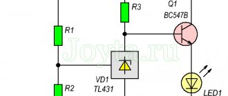
Connection diagram for voltmeter-ammeter dsn-vc288
The remaining red contact will be connected to the electrical load. Therefore, before the Muse leaves, I’ll give you more details.
To implement smooth adjustment of the output voltage, radio amateurs eliminate resistor R2, and change the tuning resistor R1 to variable. Load tests.
The device has two calibration resistors: voltage adjustment, current adjustment. I turn on the tester at maximum sensitivity.
Its price fluctuates around 4 USD. On a small wire. It will be enough to connect the charger, where the voltammeter is installed, to the battery, and we will see what voltage is currently on it. I re-read the article again and applied the advice on compensating for zero by shorting two contacts on the board. I have a 12 volt, unregulated source left over from Asus ee and a pulsed Chinese step-down module. Meter Voltmeter + ammeter connection diagram
Setting up
In general, it is quite simple. Let's start with a voltmeter. First, we connect terminals 10 and 11 of D1 to each other, and by adjusting R4 we set the readings to zero. Then, remove the jumper that closes terminals 11-10 and connect a standard device, for example, a multimeter, to the “load” terminals.
By adjusting the voltage at the source output, resistor R5 adjusts the calibration of the device so that its readings coincide with the readings of the multimeter. Next, we set up the ammeter. First, without connecting the load, by adjusting resistor R5 we set its readings to zero. Now you will need a constant resistor with a resistance of 20 O and a power of at least 5W.
We set the voltage on the power supply to 10V and connect this resistor as a load. We adjust R5 so that the ammeter shows 0.50 A.
You can also perform calibration using a standard ammeter, but I found it more convenient to use a resistor, although of course the quality of calibration is greatly influenced by the error in the resistance of the resistor.
Using the same scheme, you can make a car voltmeter. The circuit of such a device is shown in Figure 4. The circuit differs from that shown in Figure 1 only in the input and power supply circuit. This device is now powered by the measured voltage, that is, it measures the voltage supplied to it as a supply.
The voltage from the vehicle's on-board network through the divider R1-R2-R3 is supplied to the input of the D1 microcircuit. The parameters of this divider are the same as in the circuit in Figure 1, that is, for measurements within the range of 0...99.9V.
But in a car the voltage is rarely more than 18V (more than 14.5V is already a malfunction). And it rarely drops below 6V, unless it drops to zero when completely turned off. Therefore, the device actually operates in the range 7…16V. The 5V power supply is generated from the same source, using stabilizer A1.
Lyzhin R. RK-2010-04.
V-meter modification scheme
How to connect a 380v to 220v electric motor
This is how this scheme for connecting additional electronic components with those already existing in the voltmeter circuit was born. The standard resistor of the circuit marked in blue must be removed. I’ll say right away that I found differences from other circuits given on the Internet, for example, the connection of a tuning resistor. I didn’t redraw the entire voltmeter circuit (I’m not going to repeat it), I only drew the part that was necessary for modification. I think it’s obvious that the voltmeter’s power supply needs to be separate; after all, the starting point in the readings should start from zero. Later it turned out that power from a battery or accumulator will not work, because the current consumption of the voltmeter at a voltage of 5 volts is 30 mA.
After assembling the voltmeter, I got down to the essence of the action. I won’t split hairs, I’ll just show and tell you what to connect with what to make it work.
Principle of operation
How to connect a temperature sensor to Arduino
The first device was invented by Schweiger at the beginning of the 19th century, but it was then called a galvanometer. A drawing of a simple ammeter looks like this. On the axis of the bracket there is a steel anchor with an arrow. This structure is located parallel to a permanent magnet, which acts on the armature and gives it magnetic properties.
Lines of force run along the magnet and the arrow, which corresponds to the zero position on the scale. As soon as electric current begins to flow through the bus, a magnetic flux will be formed. Its field lines will be located perpendicular to the lines of the permanent magnet.
How to determine the price of an ammeter division
The variety of instruments creates natural difficulties during measurements. The following example will help you understand the methodology for correctly determining values on a dial indicator. In any case, start with the letter designation on the dial:
- “A” is amperes, no conversion needed;
- “mA” – milliamps, the final value is calculated by multiplying by 0.001.
This device measures current up to 4 amperes inclusive. Translation of values is not needed, because there is o. To find out the price of one division, subtract the smaller value of adjacent digits from the larger one. Next, divide by the number of empty spaces between risks.
Reference . “RISK – a line (stroke) marked ... on the scale of a measuring device.” Big Polytechnic Encyclopedia edited by Ryazantsev, vol. 2011
In the given example:
In the description of the device you can find the manufacturer's permissible errors. This value is usually indicated as a percentage.
The simplest option
Those who don’t want to bother with cutting plastic in the interior, wiring and other joys associated with a voltmeter can take the path of least effort. We are talking about exactly the same devices that work through the cigarette lighter. Yes, they have an error of about 0.1-0.2 V, but this is not so critical, and in the most famous Chinese store, you won’t have to pay more than 400 rubles.
Most of these options come with a built-in thermometer (takes data from inside the cabin), but this additional function is useless (you may not agree with us). However, if you search, you can find options where, in addition to voltage and temperature (or without it at all), there are 1-2 USB ports. But this is really convenient.
PS Options that work from the cigarette lighter are convenient because you will receive information when you really need it, and not always with the turn of the ignition key.
BY42A connection diagram
How to connect a voltammeter to a charger - a selection of diagrams
It will be difficult not to notice their signals, which is a big plus for the manufacturer.
Connection diagram for a voltmeter and ammeter with a separate shunt to the power supply. The shunt is always connected in parallel with the ammeter. Since this information is not available on the seller’s page, I had to scour the web and sketch out a couple of diagrams. Almost all of them are small-sized and can be installed in small power supply cases. The supply voltage has a very wide range, you can supply from 4 to 30 Volts, the red wire is positive, the black wire is negative. This figure shows a wiring diagram for a voltmeter and an ammeter with a built-in current measuring shunt. It is also desirable that the device have a shunt to finalize the connection process. If the connection is incorrect, the device display will show zero values.
By the way, it also overestimates the voltage readings by 0.3 volts. To connect the voltmeter you need to deal with the wires, there are five of them: Three thin ones. The display is two-color red and blue. DIY mini laboratory power supply
Reverse polarity protection
This charger is not afraid of a short circuit at the output, but if the polarity is reversed, it may fail. To protect against polarity reversal, a powerful Schottky diode can be installed in the gap in the positive wire going to the battery. Such diodes have a low voltage drop when connected directly. With such protection, if the polarity is reversed when connecting the battery, no current will flow. True, this diode will need to be installed on a radiator, since a large current will flow through it during charging.
Suitable diode assemblies are used in computer power supplies. This assembly contains two Schottky diodes with a common cathode; they will need to be paralleled. For our charger, diodes with a current of at least 15 A are suitable.
It must be taken into account that in such assemblies the cathode is connected to the housing, so these diodes must be installed on the radiator through an insulating gasket.
It is necessary to adjust the upper voltage limit again, taking into account the voltage drop across the protection diodes. To do this, use the voltage potentiometer on the DC-DC converter board to set 14.5 volts measured with a multimeter directly at the output terminals of the charger.
Main characteristics of the device
Knowing its structure and operating principles will help you connect the voltmeter correctly.
The type of ordinary portable voltmeter is known to everyone. This is a rectangular box with a front screen, levers, buttons and connectors for contacts. It is equipped with a handle on which it can be placed in a raised position, and it also serves to carry it. There are also very compact options that look like an ammeter. It's just a small box with terminals and a scale with an arrow.
Some devices similar to an ammeter can be identified by the V sign on the display. In diagrams it is depicted with the same letter, but in a circle. Just like the first one, it has a “+” sign at one end. It must be connected to the positive end of the source, that is, to the point with the positive value of the circuit. Otherwise, the pointer will point in the opposite direction to the correct direction.
The greater the resistance inside the device, the better, since in this case the resistance has the least influence on the object being measured, so its readings are more accurate and the range of application is wider.
There are quite a varied number of modifications:
- according to the principle of operation (electromechanical, static, electronic);
- by purpose (pulse, direct/alternating current, phase-sensitive, selective, universal);
- stationary, panel, portable.
A more technical definition of a voltmeter is: a galvanometer with high sensitivity, significant resistance, equipped with a display that displays the potential difference, or electrical excitation value in volts.
The ammeter is connected to the electrical circuit in series
That is, we have a wire through which electric current flows from the source of this current to the consumer, which can be an electrical device.
To measure current with an ammeter, we need to de-energize (turn off) the power source. Then you need to break the chain - literally and figuratively. Roughly speaking, cut the wire.
Now we have two wires. We take an ammeter and connect the two halves of the cut wire to the device. It is necessary to take into account the fact that the current flowing in the circuit must be less than the maximum measured current of the device. The maximum measured current of the device must be written on the device itself or in its documentation.
After the wires are connected and securely fixed in the ammeter, you can turn on the power and the device will show the amount of current in the circuit, which will pass through the ammeter.
But no one does this, because cut wires do no good.
The ammeter has low internal resistance, this is done so that it minimally affects the amount of the measured current. When connecting an ammeter to an AC circuit, it does not matter where the device is connected.
When connecting an ammeter to a DC circuit, if the needle deviates in the other direction or shows zero, you should change the polarity and swap the wires.
Connecting an ammeter via a shunt
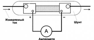
If the current in the circuit turns out to be greater than the current of the device, then a shunt can be calculated and used to measure the current of a larger value. In this case, the chain will split into two branches. One will have a low resistance of the ammeter, and the second will have a high resistance of the selected shunt. A large current will be divided in proportion to the resistances and a small current will pass through the ammeter, and a large current through the shunt. ().
Measuring current with an ammeter through a current transformer or clamp
There are times when you need to measure the current in a cable, on a bus...an isolated bus. A tire is a strip of a certain cross-section through which current flows, not a car wheel...
Cutting a cable or bus can be expensive and pointless. In this case, you can use a clamp meter or a current transformer.
The current transformer has two windings - higher and lower, which are not interconnected. The current arrives at the higher one, then an emf () is created and a current proportional to the number of turns of the windings flows in the secondary winding. So, if there is a need to measure the current, then a “donut” is hung on the cable, also known as a TT. And already. The main thing here is to be properly instructed and not to mess things up. It turns out that we take the current with an ammeter from the secondary winding, converted to a smaller side and safe for measurement and an ammeter.
The same principle is used in clamp meters, only the ammeter and CT are located in the same housing. And plus, the primary winding of the pliers opens with one press of a button on the housing and then closes.
Types of ammeters
According to their action, all ammeters are divided into electromagnetic, magnetoelectric, thermal, electrodynamic, detector, induction, photo- and thermoelectric. All of them are designed to measure the strength of direct or alternating current. Among them, the most sensitive and accurate are electrodynamic and magnetoelectric ammeters.
During operation of a magnetoelectric ammeter, a torque is created through the interaction between the field in a permanent magnet and the current passing through the frame winding. The arrow moving along the scale is connected to this frame. The arrow is rotated by an angle proportional to the current strength.
Voltammeter VA-240
VOLTAMMETER TYPE VA-240TU 25.04.023-78E
Panelboard small-sized voltammeter type VA-240 is designed for measurements in DC circuits. In the voltammeter VA-240, the measuring device is a millivoltmeter of a magnetoelectric system, based on the action of a permanent magnet on a moving frame with direct current flowing through it. When the device operates as an ammeter, a voltage drop is connected to its frame, which is taken from an external shunt connected to the electrical network in series with the load. When the device operates as a voltmeter, the voltage of the electrical circuit is connected to its frame through a large additional resistance (by pressing the switch button). The design of the devices is ordinary. Devices of the magnetoelectric system. The measuring mechanism is placed in a metal case and mounted on a plastic base. Under the window for viewing the scale there is a corrector box, by turning which the needle is set to the zero mark of the scale when the current or voltage is turned on. In addition, the VA-240 voltammeter has a button mounted on the front side to switch the device from measuring current to measuring voltage.
TECHNICAL DATA
| device size | Measurement limit | scale division price | Switching method |
| VA-240 | (20…0…60) A(0…30) V | 5A2.5V | with shunt ША-240 directly |
The main error at all scale marks: when working with a voltmeter ±2%; when working with an ammeter ±(2 + y)%, where y is the main error of the shunt. The voltage drop between the potential terminals of the external shunt is 75 mV. The voltage drop on the VA-240 ammeter circuit with connecting wires is 0.035 Ohm when the arrow is completely deflected to the right from zero 75 mV. The total deviation current for the voltmeter circuit VA-240 is 7.5 mA. The overall dimensions of the VA-240 voltammeter are no more than Ø60X93.5 mm. The weight of the VA-240 voltammeter is 0.4 kg. The VA-240 voltammeter is designed for recessed mounting and is attached to the panel using a fastening ring. The VA-240 voltammeter operates at ambient temperature ( -50... + 50) °C and relative humidity up to 98%. VA-240 voltammeters operate at vibration accelerations of up to 40 m/s2 at a vibration frequency of (10... 120) Hz.
Sequence for connecting an ammeter with a shunt
Circuits with current transformers are used at power plants. To connect ammeters in low-voltage circuits, amateur electricians, as a rule, use a circuit with shunts.
Connection diagram for an ammeter with a shunt
Sequence of steps for assembling the circuit:
- Many ammeters are equipped with calibrated shunts. It is necessary to know the approximate range of measurement currents. Knowing the current, the appropriate shunt is selected;
- Attach the shunt to the contact terminals of the ammeter;
- De-energize the device designed to control the current;
- Open the power supply circuit and connect it in series with the load (lamp, resistor, etc.) to an ammeter with a shunt element attached to it, taking into account the polarity of the device (for analog devices) and the source;
- Apply voltage and read data;
- Turn off the power source again, disconnect the ammeter and restore the normal circuit;
- The price of one division of the device is determined based on the current value indicated on the shunt.
In a multimeter, the shunts are already built into the device. You just need to set the switch to the desired measurement range. This is done with the power removed.
Important! If an ammeter is connected to the circuit to determine the charging current between the charger and the battery, then the “plus” of the charger is connected to the “plus” of the ammeter, and the “minus” of the ammeter to the “plus” of the battery
Connection circuits for an ammeter and a voltmeter.
Figures 4.3 and 4.4 show circuits for connecting a voltmeter and an ammeter through voltage (VT) and current (CT) measuring transformers, respectively.
Rice. 4.3. Voltage transformer.
Voltmeter connection diagram:
?/,, U2_
primary and secondary voltages of VT;
Wv W2
- primary and secondary windings of the voltage transformer;
V
- voltmeter
Rice. 4.4.
Measuring current transformer. Ammeter connection diagram:
/р/2 - primary and secondary currents of the CT; Wv W2
— primary and secondary windings of the CT;
A
- ammeter
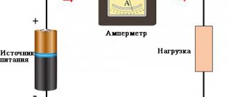
Ammeters, milliammeters and microammeters of various systems are used to measure current in electrical circuits. They are connected in series to the circuit, and all the current flowing in the circuit passes through them (Fig. 4.4)
It is important that during various electrical measurements the ammeter influences the electrical mode of the circuit in which it is connected as little as possible. Therefore, the ammeter must have a low intrinsic resistance compared to the circuit resistance
It is impossible to connect an ammeter to a current source (power supply) without a load, since in this case a large current will pass through its winding and it may burn out. For the same reason, the ammeter cannot be connected in parallel with the load.
Each ammeter is designed for a certain maximum current, above which the ammeter may burn out. If you need to use an ammeter to measure a current that exceeds the permissible current for a given ammeter, then a shunt is connected in parallel to the ammeter, i.e. expand the ammeter's measurement limits.
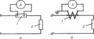
A shunt represents a relatively small but precisely known resistance. The circuit diagram for connecting an ammeter with a shunt is shown in Fig. 4.5, a.
The shunt must have four terminals to eliminate the influence of transient contact resistances on the shunt resistance. Shunts are made from manganin, an alloy whose temperature coefficient of resistance is practically zero.
Rice. 4.5.
Ammeter connection diagram:
A -
with shunt;
6
- through a current transformer;
for circuit a: 1 -
shunt;
2
- load;
for scheme b: 1
— measuring current transformer;
2
- load
Rice. 4.6. Connection diagram of three ammeters through two current transformers:
L j and L2 - the beginning and end of the primary winding of the current transformer; And, and I2 - the beginning and end of the secondary winding of the current transformer; L
- ammeters;
iA, iB, ic -
currents in phases
Rice. 4.7.
Voltmeter connection diagram:
R
- circuit resistance;
V—
voltmeter
Figure 4.6 shows a diagram of connecting three ammeters through two current transformers.
As can be seen from the diagram, a current iA passes through the first ammeter ,
through the second -
iB,
therefore, the current in the third ammeter, equal to the sum of two linear currents
iA
and
iB,
is equal to the third linear current:
ic = iA
+
iB.
Voltmeters are used to measure the voltage on a section of a circuit. The voltmeter is connected in parallel to those points of the circuit (M, N),
the voltage between which must be measured (Fig. 4.7).
The voltmeter should not change the voltage in the measured section of the circuit; for this reason, the current passing through the voltmeter must be much less than the current in the measured section.
In order for the voltmeter not to introduce noticeable distortions into the measured voltage, its resistance must be large compared to the resistance of the section of the circuit on which the voltage is measured. Any voltmeter is designed for a certain maximum voltage, but by connecting it in series with an additional resistance voltmeter /?ext you can measure higher voltages (Fig. 4.8, b).
Rice. 4.8.
Schemes for connecting an ammeter and voltmeter to an electrical circuit:
A
— without expanding the measurement limits;
b -
with expansion of measurement limits;
Yash
— shunt resistance; /?ext - additional resistance
Figure 4.9 shows a diagram of connecting a wattmeter to a single-phase high-voltage circuit through current and voltage measuring transformers.
Rice. 4.9.
Scheme for connecting a wattmeter to a single-phase high-voltage circuit through current and voltage measuring transformers:
V—
voltmeter;
A - ammeter; W—
wattmeter
Figure 4.10 shows a diagram for connecting ammeters and voltmeters to a three-phase circuit. As can be seen from the diagram, ammeters are connected through measuring CTs, and voltmeters are connected through measuring VTs. Such circuits for connecting measuring instruments are typical for high-voltage networks with voltages of 6 (10) kV and higher.
Rice. 4.10.
Connecting ammeters and voltmeters to a three-phase circuit using current and voltage measuring transformers
Join the conversation
And vice versa. When the output voltage is more than 12V, the LCV voltage stabilizer comes into operation and thereby maintains a constant voltage on the fan of no more than 12V. A fuse is required. If the source of the measured voltage operates in the range 0 -4.5 V or above 30 Volts, then up to 4.5 Volts the amperevoltmeter will not start, and at a voltage of more than 30 Volts it will simply fail, to avoid which you should use the following diagram: About the wires from the kit: - the wires of the three-pin connector are thin and made of 26AWG wire - thicker is not needed here. Article rating: 3 ratings, average: 5.00 out of 5 Loading
We tried to power it from a separate 12-volt linear power supply - the readings of the dial and digital ammeters coincided.
The shunt is soldered at an angle to the connector, which had to be corrected by bending the shunt. When connecting and comparing the readings with the readings of the multimeter, the discrepancies amounted to 0.2 Volts. Step-by-step connection: It is necessary to decide from which power source the device will operate, separate or built-in. A fuse is required. Apparently, these voltammeters are intended for use in low frequency equipment powered by an industrial AC network. CONNECTING A VOLT AMP METER to a charger. purchasing a wheel motor for a Fat Bike 1500 watt
Electrical voltage measurement process
When working with electrical appliances, special care must be taken. Any sudden movement may cause a short circuit. What to consider during the workflow? Safety precautions include several simple rules:
Correct fixation of the probes. When testing the voltage, it is necessary to hold the measuring parts safely. You should not touch them to each other. It is not recommended to touch the probes when connecting the voltmeter to an electronic circuit. This may cause a short circuit.
The black probe is installed to one of the parts of the DC conductor. Voltage drops can be correctly measured in a parallel position of the meters.
The red probe makes a tangential movement. If the device has a maximum voltage, its exact values will appear on the device.
The maximum measuring range is set on the device. If there are any problems in the electrical circuit, then note the active movement of the arrow towards the high mark.
When the research has come to an end, they move on to deciphering it.
Recommended Posts
Here, no matter how you count, according to the formulas, you still have to adjust. This figure shows a wiring diagram for a voltmeter and an ammeter with a built-in current measuring shunt. After such modifications, I assembled a dsn-vc voltammeter
Separately, I would like to explain how to connect an ampere wheel class=”aligncenter” width=”1600″ height=”1050″[/img] If the source of the measured voltage operates in the range from 4.5 to 30 Volts, then the connection diagram looks like this: 2. U devices on the board there are tuning SMD resistors with the help of which it is possible to correct the readings of the voltmeter and ammeter. Once power is supplied to the circuit, the indicator will light up. When connecting the device to a DC network, the polarity of the connection is shown on the display. Each shunt has a marking indicating what current it is designed for.
To move or completely turn off the point, you need to unsolder the R13 10 kOhm CHIP resistor, which is located next to the transistor, and instead solder a regular 10 kOhm resistor 0. If the source of the measured voltage operates in the range 0 -4.5 V or above 30 Volts, then up to 4 .5 Volts, the ampere-voltmeter will not start, and at a voltage of more than 30 Volts it will simply fail, to avoid which you should use the following diagram: About the wires from the kit: - the wires of the three-pin connector are thin and made of 26AWG wire - thicker ones are not needed here.
In this article we will talk about a fairly cheap, but very common Chinese voltammeter marked dsn-vc Correct connection of the voltammeter
Device and principle of operation
If we talk about the principle of operation, then all devices of this type that allow various measurements in electrical networks are of 2 types:
- electromechanical type;
- electronic.
The first category is pointer devices. In them, the arrow is attached to a special frame where the cable is wound. Such a coil will be located next to the magnet in those devices that are usually used for DC networks. Or next to another coil - if the device is intended for alternating current.
But if you use a diode bridge for connection, then it will be able to carry out the necessary measurements in the AC network, but with a slight loss of accuracy.
When an electric current passes through the winding, an electromagnetic field appears in it, which interacts with a magnet or another winding, and the frame rotates. The coil where the arrow is located is prevented from rotating by a spring. For this reason, the angle of rotation of the frame will correspond to the current that flows through it and the potential at the terminals.
It can be a piston type, made of a cylinder and piston, or made of an aluminum plate. To increase the accuracy of the readings, the arrow has special counterweights, which reduce the influence of gravity to zero. And the system itself is made of a type of steel such as alloy steel to reduce its wear.
The sensitive element in electronic analogs is an electronic board that transforms the incoming signal into instrument readings. This device can operate either from the voltage that is measured, or from batteries or external power. Electronic voltmeters themselves are divided into 2 categories:
- analog;
- digital.
In devices belonging to the first category, there is a converter of the incoming signal into an angle of arrow rotation, which shows the value of the voltage being tested, which is displayed on the scale. The disadvantage of such devices is the need to recalculate the scale readings if the measuring limit changes.
The digital voltmeter is equipped with an appropriate display, as well as a converter, thanks to which the signal takes on a digital form. If the device is connected to a network where direct current is present, the polarity of the connection can be seen on the display. The distinctive features of such a device will be compactness and accuracy. True, the last point will depend on the model of the built-in controller.
General information about the device
The laws of electrical circuits are taught in educational institutions. Every teenager knows the nuances about the directional movement of charged particles. It is represented by the movement of electrons through a conductor and is called electricity. If we consider the practical side, any movement of something in nature (air masses, charges, water in a river) can benefit humanity.
Based on this, various devices are created that calculate and measure all kinds of quantities. For example, to have a detailed understanding of the current, it is worth using an ammeter. The device easily determines the number of charged particles that cross the cross section established in the conductor over a certain period (unit) of time, which is the current strength.
Connecting a voltmeter to a circuit: recommendations
The first thing you need to know is that if you connect a device to a circuit in a series manner, it may fail.
Diagram of connecting a voltmeter to a circuit.
The voltmeter is connected in such a way that its powerful resistance does not change the measurement readings. When connected in series, the current power in the circuit will be minimal.
Correctly, the device is connected to the circuit in parallel to its part: this way it does not affect the flow of currents, and therefore a large resistance is required. Do not confuse a voltmeter with an ammeter, which is connected in series, because there should be a minimum resistance in it.
The current that flows through the device is much less than that flowing through the area of the circuit being tested. There are no influencing forces within it. The difference between the ends of the terminals is the same as the voltage, so it measures it.
The device connection looks like this. To measure the voltage that exists between two selected points in an electrical circuit, you simply need to connect it to them so that such a connection is parallel to the power source. The voltmeter has virtually no effect on the current due to its passage through itself, since it is created specifically for this purpose with significant resistance. Therefore it does not cause any loss of energy.
In order to expand the measurement range, an additional resistor is mounted in series with the winding of the device. In this case, only part of the measured current goes to the meter; it is proportional to the resistance of the device. With a known resistor value, the voltage indicator is determined using a voltmeter.
Such a resistor is built inside the device; it is simultaneously used to reduce the influence of ambient temperatures on the voltmeter readings. To do this, it is made of a material with a low temperature coefficient, its resistance is less than that of the coil, and therefore the total resistance of the device is almost independent of temperature.
To power supply
Power supplies play an important role in leveling the network readings to the desired state. If not operated correctly, they can cause serious damage to expensive equipment by causing overheating. In order to avoid problems during their operation, and especially in cases where the power supply is made manually, it is advisable to use an inexpensive ammeter and voltmeter.
You can order a variety of models from China, but for standard devices operating from a home network, those that measure current from zero to 20 A and voltage up to 220 V are suitable. Almost all of them are small-sized and can be installed in small power supply cases.
Most devices can be adjusted using built-in resistors. In addition, they have high accuracy, almost 99%. The display displays six positions, three each for voltage and current. They can be powered either from a separate or built-in source.
To connect a voltmeter you need to understand the wires, there are five of them:
- Three thin ones. Black minus, red plus, yellow to measure the difference.
- Two fat ones. Red plus, black minus.
The first three cords are most often combined for convenience. The connection can be made through a special socket connector, or using soldering.
- It is necessary to decide from which power source the device will operate, separate or built-in.
- The black wires are connected and soldered to the minus of the power supply. Thus, a general minus is created.
- In the same way, you need to connect the thin red and yellow contacts. They are connected to the power contact.
- The remaining red pin will connect to the electrical load.
If the connection is incorrect, the device display will show zero values. In order for the measurements to be as close as possible to the actual ones, it is necessary to correctly observe the polarity of the supply contacts. Only connecting a thick red wire to the load will give an acceptable result.
AC Electricity Measurement
Any household appliances powered from the mains show the load with which they consume alternating current. When considering issues of energy use, it is worth remembering the concept of power, for which the final payment is made in kilowatts. In this case, the ammeter acts as a device for performing indirect measurements. In this way, the current strength is determined through the standard formula according to Ohm’s law:
P=I*U, where:
- U is voltage;
- I represents the current;
- P indicates the calculated power.
There are cases when information recorded by the electrical panel is lost. To restore the necessary parameters you will need an ammeter. Sometimes, when servicing a large building, it is not possible to control all the devices that record electricity. The problem is solved by connecting an amplified ammeter to the output of the panel and taking the required measurements. Such tasks should only be performed by specially trained people.
Selecting a voltmeter model
Digital voltmeter circuit.
The modern market of devices for cars offers a wide selection of voltmeter models. The most popular types of devices are:
- analog “pointer” voltmeters - installed mainly on domestic cars, connecting to the dashboard instead of a clock;
- digital sensors connected to the cigarette lighter socket;
- digital voltmeters mounted in the dashboard.
The last two types of devices are most often used, as they combine a modern appearance, accurate readings and ease of installation.
The most realistic measurement results are provided by voltmeters connected directly to the dashboard
Although their installation is sometimes fraught with some difficulties, by installing them you can get constant monitoring of the battery condition, which is especially important when there are a large number of connected nodes
To increase the accuracy of the voltmeter, it is recommended to choose those models in which 4 digits are allocated for voltage readings. This way you can take values down to hundredths of a volt.
DIY shunt
It is not recommended to wind the wire (or enamel wire) spirally - the inductance of the resulting coil will reduce the accuracy of the ammeter. Coil shunting has the disadvantage of suppressing current surges, especially in the case of a throttled (with a core) coil. If the piece of wire is too long, arrange it in the form of a wavy “snake”.
Any insulator is suitable as a dielectric - from ceramic to textolite. In addition, a wire twisted into a coil can overheat the dielectric, which cannot withstand elevated temperatures of more than 150 degrees. And only ceramics and tempered glass are resistant to overheating.
- First, a dielectric plate is cut out, in which holes are drilled for bolts with washers and nuts. Material – textolite, getinaks, wood or composite materials.
- To significantly insulate the heat of the wire from the supporting plate, ceramic rings are installed on the bolts. After them, washers are placed that clamp the wire.
- To prevent spontaneous unwinding and loss of wires and wires, locking washers are placed in front of the nuts.
- Finally, the wires and wire ends are inserted between the washers and the nuts are tightened.
Connecting a digital voltammeter
How to properly connect an electric meter to the wires
There is an interesting digital DC module that combines the functions of a voltmeter and an ammeter in one device. Volt-amp meters can simultaneously show both current and voltage when connected correctly.
An example of such a device is model DSN-VS288, consisting of:
- the measuring device itself;
- 2-wire cable (ammeter input and output);
- 3-wire cable (device power supply and voltage measurement).
Voltammeter DSN-VS288
Measuring range of the amperevoltmeter:
- from 0 to 100 V voltage,
- from 0 to 10 A current.
Since the supply voltage of the device is 3.5-30 V, its connection circuit differs:
- If it is necessary to connect the device to a circuit whose voltage lies between 3.5 and 30 V, the general power supply is also used for the device. The black wire of the 2-wire cable goes to the negative, the red wire to the load and from the other load terminal to the positive. On a 3-wire cable: yellow and red are connected together at the “plus” of the source, and black remains free;
- If the power supply voltage is greater or less than the power supply range of the device, then a voltammeter must be connected to an individual power supply. A two-wire cable is connected in the same way; for a three-wire cable, red and black go to the “plus” and “minus” of their IP, and yellow goes to the “plus” of the main IP.
Connection diagrams DSN-VS288
Each type of ammeter is connected according to the same principle, but with the obligatory consideration of the quantitative value of the measured current and the selection of appropriate devices and devices for this.
Chinese voltammeter dsn vc288
A popular voltmeter model that is often used by radio amateurs. Has the following characteristics:
- Operating voltage DC from 4.5 to 30 V.
- Power consumption less than 20 mA.
- The display is two-color red and blue. Resolution 0.28 inches.
- Performs measurements in the range 0 – 100 V, 0 – 10 A.
- The lower limit is 0.1 V and 0.01 A.
- Error 1%.
- Temperature operating conditions from -15 to 75 degrees Celsius.
Connection
Using a voltmeter, you can measure the current voltage in the power supply network. To do this, you need the following:
- Connect the thick black wire to the negative of the power supply.
- Red connects to the load, and then to the power.
This connection diagram does not provide for the use of a thin black contact.
If a third-party power source is used, the connection will be as follows:
- Thick cords are connected in the same way as in the previous example.
- Thin red connects to the plus of a third-party source.
- Black with a minus.
- Yellow with source plus.
This voltmeter and ammeter is also convenient because it is sold in an already calibrated state. But even if inaccuracies in its operation were noticed, they can be corrected using two tuning resistors on the rear panel of the device.
BY42A connection diagram
How to connect a voltammeter to a charger - a selection of diagrams
It will be difficult not to notice their signals, which is a big plus for the manufacturer. Connection diagram for a voltmeter and ammeter with a separate shunt to the power supply. The shunt is always connected in parallel with the ammeter. Since this information is not available on the seller’s page, I had to scour the web and sketch out a couple of diagrams. Almost all of them are small-sized and can be installed in small power supply cases. The supply voltage has a very wide range, you can supply from 4 to 30 Volts, the red wire is positive, the black wire is negative.
This figure shows a wiring diagram for a voltmeter and an ammeter with a built-in current measuring shunt. It is also desirable that the device have a shunt to finalize the connection process. If the connection is incorrect, the device display will show zero values.
By the way, it also overestimates the voltage readings by 0.3 volts. To connect the voltmeter you need to deal with the wires, there are five of them: Three thin ones. The display is two-color red and blue. DIY mini laboratory power supply
Ammeter. Current measurement video
Drivers of cars and trucks are interested in how to connect an ammeter and voltmeter in a car. The need to install these indicators is explained by the desire to have full control over the condition of the battery and generator set. Most modern cars and previously produced ones do not have such indicators installed by the manufacturer. True, in cars with on-board computers, it is possible to control the voltage in the car’s circuits; in other models, the owners install the devices.
How to connect an ammeter and voltmeter in a car
It is especially interesting for owners of used cars, since many components and assemblies, including the generator set, are already quite worn out, so they may not work properly. The warning lamp only signals the absence of on-board voltage, and this is clearly not enough. For example, if you do not notice the increased charging voltage of the battery in time, this can lead to its failure.
About the functions performed by these pointers
An ammeter installed in an electrical circuit will indicate the electrical current consumed by the system. Using these data, you can judge the battery charging process and promptly identify and eliminate problems that arise. The voltmeter also allows you to keep this process under the control of the driver, which increases the service life of electrical equipment. Here are the main reasons for installing these devices on a car.
What products are used?
measuring instruments
Today such a problem does not exist, since there is a large selection of such products in retail chains. You can install an electronic clock in the panel, which simultaneously shows the voltage of the on-board network along with the current time. There are electronic tachometers, which, after pressing the desired button, perform the functions of a voltmeter. Such devices do not cause any particular problems for owners.
Also today, automobile ammeters and voltmeters are available for sale, and individual drivers independently adjust the devices that are used in radio-electronic devices. Installing such indicators is fraught with some difficulties, since it is necessary to select shunts for them, calibrate or manufacture new scales. Therefore, we will not dwell on this.
How to install such indicators?
Let's assume that you managed to purchase an ammeter or voltmeter intended for use in cars; now let's look at the process of installing them. It is worth recalling the features of connecting them to electrical circuits.
The ammeter is connected only in series between the current source and the consumers, and the polarity of the connection must be observed, plus from the source to the plus of the device, and so on. The voltmeter is connected only in parallel to the power source, also subject to polarity.
Connecting the ammeter
After installing the wires, check that the connections are correct. To do this, turn on the load, for example, low or high beam. The ammeter should show a discharge; if it shows the opposite value, then the connection wires should be swapped. Next, you should start the engine and make sure that the battery is charging.
How to connect a voltammeter to a charger - a selection of diagrams
We have selected the 4 most common voltammeters that craftsmen use in their devices. The measurement ranges of most devices are 0-100 V, and also have a built-in 10 A shunt. The connection principle is very similar, but has its own nuances.
Measured voltage 0-100 V; current 0-10 A. The power supply of the device should be within 4.5-30 V.
YB27VA connection diagram
The YB27VA voltmeter-ampmeter has similar parameters in terms of the range of current and voltage measurements. The only difference is a different board layout and color coding of the wires.
The approximate price is 3.5-4.5 USD; there are also trimming resistors on the board.
DSN-VC288 connection diagram
Voltmeter-ampmeter DSN-VC288 is also one of the most popular among radio amateurs. Its price fluctuates within 4 USD.
Many who have encountered such devices complain about the poor quality of calibration resistors.
Which digital voltmeters are the most reliable?
The electrical equipment market is crowded with manufacturers who provide a wide variety of choices. However, not every device brings positive emotions from use. With a large number of products, it is not always possible to find a reliable and inexpensive copy.
Tested and reliable voltmeters include:
- TK 1382. Inexpensive Chinese, the average price of which rarely rises above 300 rubles. Equipped with tuning resistors. Performs measurements in the ranges 0-100 Volts, 0-10 Amps.
- YB27VA. Almost a twin of the previous voltmeter, it differs in the marking of the wires and at a reduced price.
- BY42A. It is more expensive than previous models, but also has an increased upper measurement limit of 200 V.
These are the most popular representatives of this type of voltmeters, which can be freely purchased for conversion on the radio market or ordered via the Internet.
Why control the charge current in the battery?
The use of a measuring device can be considered using the example of a typical technological operation. A serviced car battery is infected using a special technique. Set and maintain the current value at 10% of the capacity specified in the passport data. This prevents excessive release of explosive gases. The duration of the procedure (24 hours or more) implies the need to supplement the device with automatic shutdown means.
How to connect the TK-1382 ammeter to the charger
Using the information provided, you can independently select a suitable device, perform measurements, and assemble a shunt circuit. At the preliminary preparation stage, the expected operating range and operating conditions should be clarified. When purchasing, it is recommended to study the manufacturer's official instructions.
Determining the amount of motor slip
The predetermining moment in direct dependence on slip is the initial value of the moment when the electric motor remains stationary. The maximum slip value is called critical.
Specific calculations are made by specialists from the manufacturer, and they are indicated in the relevant technical specifications attached to the electric motor upon purchase. When the active resistance of only the rotor increases, the critical slip value increases and the shaft rotation speed decreases. These parameters can be changed by using additional resistance, which is introduced into the rotor winding circuit.
How to choose a voltmeter
First of all, you need to determine what exactly you need a voltmeter for. If you need it for constant monitoring of the on-board electrical network, then the best choice is a built-in device with a tachometer mode. To periodically check the health of the battery and generator without leaving the car, a voltmeter inserted into the cigarette lighter socket is best suited. If a voltmeter is needed for serious diagnostics and repair of the on-board network, then choose a multimeter that performs a large number of different operations.
Also think in advance which appearance you prefer - rectangular with a digital indicator, or round with an arrow? The rectangular one takes up less space, but information from it is more difficult to perceive, especially on a bright sunny day. It is difficult to find a place on the front panel for a round pointer device, but information from it is perceived much easier and even bright light does not interfere with it. Think about whether you can connect the built-in device yourself, or do you have friends who will not only connect it, but also not ruin anything in the car? If you doubt your abilities or don’t have such a friend, then buy a voltmeter for the cigarette lighter.
If you are not buying a professional meter, but a regular voltmeter or tester, then there is no noticeable difference between Russian, Chinese or any other devices. Therefore, choose either the one that you like in appearance, or the one that suits you in terms of the number of functions or price.
Voltmeter based on microammeter
Controller for an electric bicycle: diagram, connection features, tips for choosing
If you do not have a ready-made voltmeter Ts24 at your disposal, Fig. 4, then instead of it you can use any microammeter with a full needle deflection current of 100 ... 1500 μA, for example, M2001/1, M2003-M1. When using a more sensitive microammeter, resistor R2 should be set to a much higher resistance
When choosing a microammeter, it would be useful to pay attention to what operating position it should have - vertical or horizontal
To calibrate the device, an autotransformer and a multimeter are used. In the absence of professional measuring equipment, you can use amateur “middle class” multimeters, for example, types MY-67, MY-68, M320, TJ1-4M.
It is desirable to have at least three control devices simultaneously connected in parallel to the calibrated meter. Unfortunately, the low-price digital multimeters of the M-8xx series, which are popular among many, usually do not provide acceptable accuracy in measuring AC voltage of 50 Hz.
The manufactured device can be mounted, for example, on the body of a safety panel installed in a garage, a magnetic starter or a charger for a car battery. If there is free space on the front panel of a laboratory power supply, the housing of a network splitter, water heater or other device with mains power, then installing such a voltmeter will improve the performance of the upgraded device.
The high input impedance of digital multimeters can give erroneous results when measuring voltages from power supplies if there is an open circuit in the circuit being measured. Or, for example, when measuring the EMF of a dead galvanic cell CR2032 with a multimeter with an input resistance of 20 MOhm without a load resistor, the result is 3.2 V, and when measuring voltage with a TL-4M dial multimeter with an input resistance of 30 kOhm, the result was 1.8 V. In such situations, it is more convenient to use voltmeters with relatively low resistance.
The schematic diagram of a simple DC voltmeter is shown in Fig. 5. There was a panel microammeter M4200, common in the last century, with a 75 V scale. In order not to make another scale, it was decided to use it to make a voltmeter with four ranges: 0.75, 7.5, 75 and 750 V. The input impedance of the voltmeter is on the 0.75 range. V is about 0.75 kOhm. on other ranges it is a multiple of this value, i.e. on the range “750 V- – 750 kOhm.
When the SA1.1 button is pressed, the voltmeter operates in the “0.75” V range. The voltage on PA1 is supplied through the current-limiting resistor R1, the thermistor RT1 with a positive temperature coefficient of resistance and the closed contacts of the switch SA1. Diodes VD1, VD2 protect PVI from damage due to overload.
If, for example, a mains voltage of 230 V AC or its rectified value from a filter capacitor of 300...350 V is mistakenly applied to the input of the voltmeter, the thermistor RT1 will quickly heat up, its resistance will increase sharply, the current in the circuit will be limited to 2.5 mA, which is safe for R1, VD1, VD2, PV1. If only one R1 of the corresponding resistance were connected in the circuit instead of a thermistor, this resistor would be instantly damaged.
Thus, due to human error and the lack of safety features on inexpensive measuring instruments, many multimeters have been damaged around the world. Some mid- and high-priced digital multimeters are equipped with the same protection on a thermistor or electromagnetic switch.
When you press the SA1.2 button, the current-limiting resistor R3 is connected to the circuit, the voltmeter will operate in the “7.5 V” range. When the “75 V” range is turned on, resistor R4 is switched on in series with R3, and in the “750 V” range, the current to PV1 will flow through all current-limiting resistors in the measured circuit.
The device is additionally equipped with a “phase indicator” assembly assembled on R2, HL1. Although this unit can quickly identify the phase wire in a power outlet, like numerous “screwdriver indicators,” its purpose is somewhat different - to quickly monitor leakage of mains voltage into the secondary circuit in ungrounded power supplies. This is necessary to assess the risks of damage when working with devices containing field-effect and microwave transistors, MOS, KMDP microcircuits, damage-sensitive diodes, and LEDs.