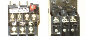
During a long working process, the windings of any electric motor overheat and the insulating coating deteriorates. Such situations often lead to interturn short circuits, burnout of poles and other negative consequences that require urgent and expensive repairs. A thermal relay for the electric motor, installed in the power circuit and providing reliable protection against overheating, helps to avoid this.
Well, now let's move on to calculating the correct setting of the thermal relay!
Let's take the Grundfos pump as an example.
We take the input data for the calculation from the plate on the electric motor.
f = 60 Hz
U = 220-277 ∆ / 380-480 Y V
Formula for calculating the rated current (full load current) In = 5.70 - 5.00 / 3.30 - 2.90 A
Let's imagine that:
- Ua = actual voltage 254 ∆ / 440 Y V (actual voltage)
- Umin = 220 ∆ / 380 Y V (minimum values in the voltage range)
- Umax = 277 ∆ / 480 YV (Maximum values in the voltage range)
The voltage ratio is determined by the following equations:
- For the connection diagram, triangle UΔ = (UA - Umin) / (Umax - Umin), which in this case: UΔ = (254 - 220) / (227 - 220) = 0.6
- For the star connection diagram UY = (UA - Umin) / (Umax - Umin), which in this case: UY = (440-380) / (480-380) = 0.6
And so we get that UΔ = UY
Operating principle of the device
Thermal overloads in motors and other electrical devices occur when the amount of current passing through the load exceeds the rated operating current of the device. The TR is based on the property of current to heat up a conductor as it passes through. The bimetallic plates built into it are designed for a certain current load, exceeding which leads to severe deformation (bending).
The plates press on a movable lever, which, in turn, acts on a protective contact that opens the circuit. In fact, the current at which the circuit opens is the tripping current. Its value is equivalent to the temperature, exceeding which can lead to physical destruction of electrical appliances.
Modern TRs have a standard group of contacts, one pair of which is normally closed - 95, 96; the other is normally open - 97, 98. The first is intended for connecting the starter, the second is for signaling circuits. The thermal relay for an electric motor can operate in two modes. Automatic provides for independent switching on of the starter contacts when the plates are cooled. In manual mode, the operator returns the contacts to their original state by pressing the “reset” button. You can also adjust the device’s response threshold by rotating the adjusting screw.
Another function of the protective device is to turn off the motor in case of phase loss. In this case, the motor also overheats, consuming more current, and, accordingly, the relay plates break the circuit. To prevent the effects of short circuit currents, from which the TR is unable to protect the engine, a circuit breaker must be included in the circuit.
Now let's calculate the actual full load current of our pump (I)
- Current for values with a delta connection diagram: 5.70 + (5.00 - 5.70) × 0.6 = 5.28 = 5.30 A
- Current for values with a star connection diagram: 3.30 + (2.90 - 3.30) × 0.6 = 3.06 = 3.10 A
The main rule is that the motor thermal overload relay is always set to the rated current indicated on the nameplate.
However, if motors are designed with a performance factor in mind, which is then stated on the nameplate, e.g. 1.15, the specified current for an overload relay can be increased by 15% over the full load current or the ampere service factor, which is usually indicated on the nameplate.
CONCLUSION: in our case, the motor is connected according to the star circuit = 440 V 60 Hz, the overload relay should be set to 3.1 A.
How does thermal protection work?
The operating principle of a thermal relay is related to the ability of metals to expand when heated. Two plates made of different metals are mounted in the device. But their coefficients of thermal expansion are different. The elements are rigidly connected to each other.
When the system is overloaded, an increase in current strength is required to continue operation. The process is accompanied by intense heat release. The contact plates heat up and become bent towards the area with a lower temperature coefficient.
Moreover, everything proceeds sequentially. Difficulties in motor operation increase the current strength. The stronger the latter, the faster the heating takes place. A plate brought to the emergency incandescence limit will bend and open the contract in a section of the circuit.
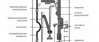
The structure of a thermal relay Source oboiman.ru
When installing thermal relays to protect electric motors, the climatic conditions in the building should be taken into account. If it is very hot in the area where the motor is operating, then when setting the relay it is necessary to set the maximum parameters with a margin. To compensate for temperature differences.
Since the contact material becomes very hot before operation, it must be given time to cool down. Otherwise, the device will turn off the system again after a short time. But, as a rule, during the time the problems are corrected, the bimetallic plates manage to return to normal.
The thermal relay consists of:
- heating element;
- bimetal plates;
- pusher;
- temperature compensator;
- latches;
- release rods;
- contact group;
- springs.
Let's figure out how thermal protection of an electric motor occurs. Current constantly passes through the heating element. If the temperature of the latter increases, then the system has begun to work under load. When a given overload parameter is reached, the bimetallic plate becomes deformed.
Deformation of a bimetallic plate Source meteo59.ru
It moves the pusher, which activates the temperature compensator. The latter moves the latch to the side so that the release rod can rise up and open the contact group. And to return everything to its original position, you need a spring, which is activated by a special button.
Tags
thermal relay electrothermal relay Electrothermal relays are designedelectrothermal relay is presentedelectrothermal relay.thermal relay protectionelectrothermal relays.Thermal relay LRD06 Thermal relay Thermal relayoperating current.according to the power supply current.operating current.increasing load currentcurrent magnitude and current values current duration at the operating current regulatorconnection of thermal relayfunctioning thermal release .thermal work releases
site articles features electricians devices
Types of thermal protection relays
It should be noted that on the modern market of electrical products there are different types of thermal protection modules for electric power units. Each of these types of devices is used in a specific situation and for a specific type of electrical equipment. The main types of thermal protection relays include the following designs.
Read also: The act of measuring the temperature in the apartment
- RTL — an electromechanical device that provides high-quality thermal protection of three-phase electric motors and other power plants from critical overloads in current consumption. In addition, a thermal relay of this type protects the electrical installation in the event of an imbalance in the supply phases, a delayed start-up of the device, as well as in case of mechanical problems with the rotor: shaft jamming and so on. The device is mounted on PML contacts (magnetic starter) or as an independent element with a KRL terminal block.
- PTT — a three-phase device designed to provide protection for electric motors with a squirrel-cage rotor from current overloads, imbalance between supply phases and mechanical damage to the rotor, as well as from prolonged starting torque. It has two installation options: as an independent device on a panel or combined with magnetic starters PME and PMA.
- RTI — a three-phase version of an electrothermal release that protects the electric motor from thermal damage to the windings when current consumption values are critically exceeded, from a long starting torque, asymmetry of the supply phases and from mechanical damage to the moving parts of the rotor. The device is installed on magnetic contactors KMT or KMI.
- TRN — a two-phase device for electrothermal protection of electric motors, providing control of the start duration and current in normal operating mode. Returning contacts to their original state after an emergency operation can only be done manually. The operation of this release is completely independent of the ambient temperature, which is important for hot climates and hot industries.
- RTK - an electrothermal release, with which you can control a single parameter - the temperature of the metal casing of the electrical installation. Control is carried out using a special probe. If the critical temperature value is exceeded, the device disconnects the electrical installation from the power line.
- Solid State - a thermal relay that does not have any moving elements in its design. The operation of the release does not depend on the temperature in the environment and other characteristics of the atmospheric air, which is important for explosive industries. Provides control over the duration of acceleration of electric motors, optimal load current, breakage of phase wires and jamming of the rotor.
- RTE - a protective thermal relay, which is essentially a fuse. The device is made of a metal alloy with a low melting point, which melts at critical temperatures and breaks the circuit that powers the electrical installation. This electrical product is mounted directly into the housing of the electric power plant in a standard place.
From the above information, it can be seen that there are currently several different types of electrothermal relays. All of them are used to solve one single problem - protecting electric motors and other power electrical installations from current overloads with an increase in the temperature of the working parts of the units to critical values.
What to consider when installing a relay
It is important to remember that the bimetallic strip can heat up not only from the passing current, but also from the ambient temperature. This primarily affects the response speed, although there may not be any overcurrent. Another option is when the motor protection relay falls into the forced cooling zone. In this case, on the contrary, the motor may experience thermal overload, and the protection device may not operate.
To avoid such situations, you should adhere to the following installation rules:
- Select a relay with a permissibly higher response temperature without compromising the load.
- Install the protective device in the room where the engine itself is located.
- Avoid places with increased heat radiation or proximity to air conditioners.
- Use models with built-in temperature compensation function.
- Use the plate activation adjustment, adjust according to the actual temperature at the installation site.
Connection, adjustment and marking
The overload switching device, unlike an electrical circuit breaker, does not break the power circuit directly, but only sends a signal to temporarily shut down the facility in emergency mode. Its normally switched contact works as a contactor “stop” button and is connected in a series circuit.
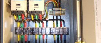
Device connection diagram
In the relay design, there is no need to repeat absolutely all the functions of the power contacts upon successful operation, since it is connected directly to the MP. This design allows for significant savings in materials for power contacts. It is much easier to connect a small current in the control circuit than to immediately disconnect three phases with a large one.
In many schemes for connecting a thermal relay to an object, a permanently closed contact is used. It is connected in series with the “stop” button of the control panel and is designated NC - normally closed, or NC - normal connected.
An open contact with such a scheme can be used to initiate the operation of thermal protection. Connection diagrams for electric motors in which a thermal protection relay is connected may vary significantly depending on the presence of additional devices or technical features.
In a standard simple circuit, the TP is connected to the output of a low-voltage starter on an electric motor. Additional contacts of the device must be connected in series with the starter coil
This will provide reliable protection against electrical equipment overloads. In case of unacceptable excess of current limit values, the relay element will open the circuit, instantly disconnecting the MP and the engine from the power supply.
The connection and installation of a thermal relay, as a rule, is carried out together with a magnetic starter designed for switching and starting an electric drive. However, there are types that are mounted on a DIN rail or a special panel.
Subtleties of adjusting relay elements
One of the main requirements for electric motor protection devices is the precise operation of the devices in the event of emergency operation of the motor. It is very important to select it correctly and adjust the settings, since false positives are absolutely unacceptable.
An electrothermal relay, which is optimally suited to a specific type of engine in all technical parameters, is capable of providing reliable protection against overloads in each phase, preventing a prolonged start of the installation, and preventing emergency situations with jamming of the rotor
Among the advantages of using current protection elements, one should also note a fairly high speed and a wide response range, and ease of installation. To ensure timely shutdown of the electric motor during overload, the thermal protection relay must be configured on a special platform/stand.
In this case, inaccuracy due to the natural uneven spread of rated currents in the NE is eliminated. To test the protective device on a bench, the fictitious load method is used.
A reduced voltage electric current is passed through the thermocouple to simulate the actual thermal load. After this, the exact time of operation is accurately determined using the timer.
When setting up basic parameters, you should strive for the following indicators:
- at 1.5 times the current, the device should turn off the engine after 150 s;
- at 5...6 times the current it should turn off the motor after 10 s.
If the response time is not correct, the relay element must be adjusted using the control screw.
For correct operation, it is necessary to set the device to the highest permissible electric current of the motor and air temperature
This is done in cases where the rated current values of the NE and the motor differ, as well as if the ambient temperature is below the nominal one (+40 ºC) by more than 10 degrees Celsius.
The operating current of the electrothermal switch decreases with increasing temperature around the object in question, since the heating of the bimetallic strip depends on this parameter. If there are significant differences, it is necessary to further adjust the thermocouple or select a more suitable thermoelement.
Sharp temperature fluctuations greatly affect the performance of the current relay. Therefore, it is very important to choose a NE that can effectively perform basic functions, taking into account real values.
It is recommended to place the TR in the same room as the protected electrical installation. They should not be installed close to heat generators, heating furnaces and other heat sources.
These restrictions do not apply to temperature compensated relays. The current setting of the protective device can be adjusted in the range of 0.75-1.25x from the rated current of the thermoelement. The setup is done in stages.
First of all, the correction E1 is calculated without temperature compensation:
E1=(Inom-Ine)/c×Ine,
Where
- In – rated motor load current,
- Ine – rated current of the working heating element in the relay,
- c is the price of the scale division, that is, the eccentric (c=0.055 for protected starters, c=0.05 for open ones).
The next step is to determine the E2 correction for ambient temperature:
E2=(ta-30)/10,
Where ta (ambient temperature) is the ambient temperature in degrees Celsius.
The last stage is finding the total correction:
E=E1+E2.
The total correction E can be with a “+” or “-” sign. If the result is a fractional value, it must be rounded down to a whole number downwards/larger in magnitude, depending on the nature of the current load.
To adjust the relay, the eccentric is transferred to the resulting value of the total correction. A high response temperature reduces the dependence of the operation of the protective device on external indicators.
The thermal protection relay allows manual smooth adjustment of the device's operating current within ±25% of the rated current of the electromechanical installation
The adjustment of these indicators is carried out by a special lever, the movement of which changes the initial bend of the bimetallic plate. The operation current can be adjusted over a wider range by replacing the thermoelements.
Modern overload protection switching devices have a test button that allows you to check the serviceability of the device without a special stand. There is also a key to reset all settings. They can be reset automatically or manually. In addition, the product is equipped with an indicator of the current state of the electrical appliance.
Marking of electrothermal relays
Protective devices are selected depending on the power of the electric motor. The main part of the key characteristics is hidden in the symbol.
This is what the marking of thermal relays from the KEAZ plant looks like. When choosing, it is important to pay attention to the rated current of the model in question so that it is sufficient
You should focus on certain points:
- The range of setting current values (indicated in parentheses) varies minimally among different manufacturers.
- The letter designations for a specific type of execution may vary.
- Climatic performance is often presented in the form of a range. For example, UHL3O4 should be read as follows: UHL3-O4.
Today you can buy a variety of device variations: relays for alternating and direct current, monostable and bistable, devices with deceleration when turned on/off, thermal protection relays with accelerating elements, thermal protection relays without a holding winding, with one winding or several.
These parameters are not always displayed in the labeling of devices, but must be indicated in the data sheet of electrical products.
The following article will introduce you to the structure, types and markings of an electromagnetic relay, which we recommend that you read.
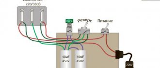
Connection process
Below is a TP connection diagram with symbols. On it you can find the abbreviation KK1.1. It denotes a contact that is normally closed. The power contacts through which current flows to the motor are designated by the abbreviation KK1. The circuit breaker located in the TP is designated as QF1. When it is activated, power is supplied in phases. Phase 1 is controlled by a separate key, which is marked SB1. It performs an emergency manual stop in case of an unexpected situation. From it the contact goes to the key, which provides start-up and is designated by the abbreviation SB2. The additional contact, which extends from the start key, is in standby condition. When starting is performed, then the current from the phase through the contact is supplied to the magnetic starter through the coil, which is designated KM1. The starter is triggered. In this case, those contacts that are normally open are closed and vice versa.
When the contacts, which are abbreviated KM1 in the diagram, are closed, then three phases are switched on, which send current through the thermal relay to the windings of the motor, which is put into operation. If the current increases, then due to the influence of the TP contact pads under the abbreviation KK1, three phases will open and the starter will be de-energized, and accordingly the motor will stop. The usual stop of the consumer in forced mode occurs by pressing the SB1 key. It breaks the first phase, which will stop supplying voltage to the starter and its contacts will open. Below in the photo you can see an improvised connection diagram.
There is another possible connection diagram for this TR. The difference is that the relay contact, which is normally closed, when activated, does not break the phase, but the zero, which goes to the starter. It is used most often due to its cost-effectiveness when performing installation work. In the process, the zero contact is connected to the TP, and a jumper is mounted from the other contact onto the coil, which starts the contactor. When the protection is triggered, the neutral wire opens, which leads to the shutdown of the contactor and motor.
The relay can be mounted in a circuit where reverse movement of the motor is provided. The difference from the diagram above is that there is a NC contact in the relay, which is designated KK1.1.
If the relay is triggered, then the neutral wire is broken by contacts designated KK1.1. The starter is de-energized and stops powering the motor. In an emergency, the SB1 button will help you quickly break the power circuit to stop the engine. A video about connecting the TR can be seen below.
Motor overload protection
The conductor heats up from the electric current passing through it. With an increase in current strength in a conductor with the same cross-section, its heating increases, that is, the load increases. In this regard, operation occurs mainly due to an increase in temperature. The same thermal energy heats the bimetallic plate, which, under the influence of temperature, bends and comes into contact through the pusher with the actuator plate of the temperature compensator. The plate disconnects the contacts in the magnetic starter and puts the device’s power button into working condition.
The temperature compensator is a kind of counterweight that reduces the effect of additional heating under the influence of ambient temperature. The plate bends in the opposite direction, and the amount of bending is adjusted with a special screw.
The trigger current regulator or eccentric has a scale of five divisions to the left and five to the right, for a corresponding increase/decrease in the current relative to the central mark. To regulate the actuation current, you need to select the required gap between the pusher and the actuator plate. Changing this value is carried out using an eccentric slider, which acts on the temperature compensator plate. After the device is triggered, it is recommended to wait some time for the thermal release to cool down. The electric motor is carefully inspected and the cause of the protection is found.
Summary
Diagrams that depict the principle of connecting a relay to a contactor may have other letter or digital designations. Most often, their decoding is given below, but the principle always remains the same. You can practice a little by assembling the entire circuit with a consumer in the form of a light bulb or a small motor. Using the test key, you can work out a non-standard situation. The start and stop keys will allow you to check the functionality of the entire circuit. In this case, it is necessary to take into account the type of starter and the normal state of its contacts. If there are any doubts, then it is better to consult an electrician who has experience in assembling such circuits.