Various emergency situations periodically occur in electrical networks. Among them, the greatest danger is short-circuit current, the formula of which is used in calculations and design. The consequences of emergency mode are quite serious - the networks themselves, as well as connected devices and equipment, fail. All this causes great material damage. The calculations carried out, including those for short-circuit shock current, are required, first of all, in order to ensure reliable protection at an electrified facility.
Calculation of short circuit currents
To perform such a current calculation, qualified specialists are involved. They not only develop the theoretical side, but are also responsible for the subsequent operation of the presented schemes. There are too many specific features here, so novice electricians must have a good understanding of not only the nature of electricity itself, but also the properties of conductors, dielectrics, insulation features and other important issues.
Results calculated at home must be checked by specialists. All calculations regarding short circuits are performed using special formulas.
A three-phase short circuit in electrical networks up to 1000V is determined taking into account the following features:
- The three-phase system is symmetrical by default.
- The transformer supply is considered unchanged, comparable to its rating.
- The occurrence of a short circuit is considered at the moment of the maximum current value.
- The EMF value is taken for power sources located at a large distance from the short circuit.
In addition, when determining the parameters of a short circuit, the total resistance of the conductors should be correctly calculated, linked to a single power value. Conventional formulas can lead to errors due to different rated voltages in individual sections at the time of short circuit. Basic power significantly simplifies calculations and increases their accuracy.
What is a phase-to-phase short circuit and how to protect against it?
It would not be a strong exaggeration to say that such an abnormal mode of operation of the electrical network as a short circuit is known even to those who have not studied the basics of electrical engineering. Today we propose to consider a special case of this phenomenon - an interphase short circuit. From the materials in our article you will learn the features of this type of short circuit and the consequences caused by it. Finally, we will look at ways to protect the electrical network from various types of short circuits.
What is phase-to-phase fault?
This is an emergency mode of operation of the electrical network caused by electrical contact of opposite phases. As an example, we give typical types of closures.
Types of short circuits
Designations:
- Three-phase short circuit.
- Short circuit of two phase wires.
- Short circuit to ground during a two-phase fault.
- Phase (single-phase) short circuit. A short circuit can occur to ground or the neutral wire in systems with an insulated or grounded neutral.
As can be seen from the figure, point 2 fits the definition of a phase-to-phase short circuit. Note that, under certain conditions, 1 and 3 can also be considered as a special case of a phase-to-phase short circuit.
Where does it occur and why?
Theoretically, a short circuit can form at any point in the network. This process is random, except in cases where a short circuit is caused forcibly, using a short circuit to quickly disconnect high-voltage power lines.
Short circuiter KZ-110
Unintentional short circuits can occur in the following places:
- On insulators, both bushings and support ones, used for live parts.
- Between the phase windings of electrical machines and electromagnetic devices, such as current transformers, motors or generators.
- In overhead and cable power lines.
- In electrical circuit switches, for example, disconnectors, switches, circuit breakers, etc.
- In circuits of equipment or other electrical consumers.
The causes of short circuits can be caused by various conditions; we list the most common electrical connections:
- Metal contact of interphase voltages with minimal transient resistance and elimination of electric arc.
- Arc faults. Strong load currents flow between phase conductors even with an air gap.
- Glowing short circuits, as a rule, occur in power cable lines when the insulation of current-carrying lines is destroyed or damaged. As a result, a zone with low resistance may form in the network section between the phase conductors, which leads to overheating of the insulation.
- Breakdown of power semiconductor elements, for example, thyristors.
Interphase short circuit current
For any type of fault, current is the main characteristic of the emergency operation of a three-phase network. This must be taken into account when developing electrical equipment, for which a special technique is used, a description of which can be found on our website.
In addition to electrical devices, calculating the short-circuit current is also necessary to select the characteristics of devices that perform protective (emergency) shutdowns, for example, circuit breakers or relay protection systems.
We list the factors on which the short-circuit current depends:
- Removing the emergency section from the power source. The greater the distance between them, the lower the short-circuit current level will be.
- Type, cross-section of current-carrying elements and length of power lines between the emergency area and the source of electricity. In this case, the parameters and state of the switches located in this circuit have an important influence. The circuit characteristics listed above allow you to calculate the equivalent load resistance required to determine the fault current.
Please note that the type of electrical connection during a short circuit affects the magnitude of the fault current. The following dependence is observed:
- The metal contact of phase voltages generates the largest amount of current. That is why when designing electrical equipment, calculations are made for a given electrical connection.
- An arc fault generates less current. But in practice, one can often observe an unstable arc, that is, periodically igniting and dying out, which leads to the formation of transient processes. They, in turn, can cause the design characteristics of the short-circuit current to be exceeded.
- A smoldering short circuit produces a current level significantly less than the calculated one, which can negatively affect the operation of circuit breakers. In practice, there have been cases where this type of fault became an arc or formed a metal contact, causing the AV to operate. But after turning on the line, the electrical connection again returned to the state of a smoldering short circuit, not recognizable by the AV. In such cases, to recognize the faulty section, it is necessary to apply increased voltage to the line or measure the insulation resistance.
Checking insulation with a megohmmeter
Consequences
Interphase short circuits can not only affect the operating modes of electrical devices, but also cause their failure. In addition, current-carrying elements are subject to both thermal and dynamic loads. The latter is typical for powerful power systems in which attraction or repulsion of conductive elements is observed. This interaction depends on the direction of the current.
In the event of an accident in high-voltage circuits, the dynamic load can lead to the destruction of insulators supporting the current-carrying lines, which only aggravates the situation.
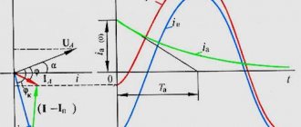
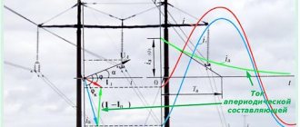
Changes in current during a short circuit
During the short circuit, the current undergoes various changes. At the very beginning it increases, then it fades to a certain value, and then the automatic excitation regulator brings it to a stable value.
The time period required to change the parameters of the short circuit current - TKZ - is called the transient process. At the end of this period and until the moment when the short circuit is turned off, a stable emergency mode is observed. The magnitude of the current at various periods of time is necessary when choosing settings for protective equipment, checking the dynamic and thermal stability of electrical equipment.
Short circuits in single-phase networks
When performing calculations of single-phase current power systems, calculations performed in a simplified form are allowed. Devices and equipment in such networks do not consume a large amount of electricity, so reliable protection can be provided by a conventional circuit breaker designed for an operating current of 25 amperes.
The single-phase short circuit current is calculated in the following order:
- Determination of the parameters of the transformer or reactor feeding the network, including its electromotive force.
- The technical characteristics of the conductors used in the network are established.
- The branched electrical circuit must be simplified, divided into separate sections.
- Calculation of impedance between phase and zero.
- Determination of the impedance of a transformer or other power supply devices, if such data is not available in the technical documentation.
- All obtained values are inserted into the formula.
Technical characteristics of current transformers TZLK-0.66 and TZLKR-0.66.
| Parameter name | Parameter value |
| Rated voltage, kV | 0,66 |
| Rated frequency, Hz | 50 or 60 |
| One-second thermal resistance current of the secondary winding, A | 140 |
| One-minute test voltage of industrial frequency, kV | 3 |
Zero sequence current transformers TZLK-0.66
| Relay type | Relay scale used, A | Setting the operating current, A | Protection sensitivity (primary current, A), no more | ||
| when working with one transformer | when connecting a transformer in series | when connecting two transformers in parallel | |||
| RT-140/0.2 | 0,1-0,2 | 0,1 | 8,5 | 10,2 | 12,5 |
| RT3-51 | 0,02-0,1 | 0,03 | 2,5 | 3,2 | 4,8 |
Zero sequence current transformers TZLKR-0.66.
| Relay type | Relay scale used, A | Setting the operating current, A | Protection sensitivity (primary current, A), no more | ||
| when working with one transformer | when connecting a transformer in series | when connecting two transformers in parallel | |||
| RT-140/0.2 | 0,1-0,2 | 0,1 | 25 | 30 | 45 |
| RT3-51 | 0,02-0,1 | 0,03 | 3 | 4 | 4,5 |
Calculation of short-circuit currents for three-phase networks
In order to determine the three-phase short circuit current in the corresponding networks, it is necessary to take into account the specifics of the occurrence and development of this process. First of all, this is the inductance that occurs in a closed conductor, due to which the current of a three-phase short circuit does not change instantly, but increases gradually in accordance with certain laws.
The accuracy of the calculations performed depends primarily on the calculations of the basic quantities inserted into the formula. For this purpose, additional formulas or special software are used that perform complex computational operations in a very short time.
If calculations in three-phase networks are performed manually, in such cases the necessary results of the short-circuit current flow, the formula given below allows you to determine with fairly accurate indicators:
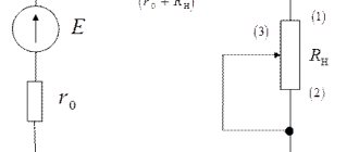
- Is = Uc/(√3*Hres) = Uc /(√3*(Xsyst + Hvn)), in which Hvn is the resistance between the busbars and the short-circuit point, Xsist is the resistance in the entire system relative to the voltage source buses, Uc is the voltage on tires in this system.
Break of one linear (phase) wire in a three-wire three-phase circuit
Asymmetrical mode of operation of a three-wire three-phase circuit
If the phase resistances are unequal z
A≠
z
B≠
z
C phase currents will also be unequal to each other
I
A≠
I
B≠
I
C.
The voltages on the phases are distributed in direct proportion to the phase resistances (the greater the resistance, the greater the voltage drop across it).
Point O can take any position in triangle ABC (Fig. 3.9),
U
A≠
U
B≠
U
C.i.e.
“phase imbalance” occurs.
Rice. 3.9. Topographic vector diagram for asymmetrical mode
loads when connecting consumers into a star
If one linear wire breaks, for example, wire A (Fig. 3.10, a), the circuit turns into a single-phase one, with receivers connected in series. If Z
B=
Z
C, then
U
B=
U
C= 0.5
U
BC (Fig. 3.10, b).
Point O moves down and divides vector U
BC into two equal parts.
If you measure the voltage between the receiver neutral and line wire A, it will be equal to 1.5 U
F.
Rice. 3.10. Scheme ( a
) and topographic vector diagram when a line wire breaks (
b
)
Your opinion is important to us! Was the published material useful? Yes | No
Source