Author: Evgeny Zhivoglyadov. Date of publication: January 29, 2013. Category: Articles.
The properties of generators are analyzed using characteristics that establish dependencies between the main quantities that determine the operation of generators. These basic quantities are: 1) terminal voltage U, 2) excitation current iв, 3) armature current Ia or load current I, 4) rotation speed n.
Typically generators operate at n = const. Therefore, the main characteristics of generators are determined at n = nn = const.
There are five main characteristics of generators: 1) no-load, 2) short circuit, 3) external, 4) regulation, 5) load.
All characteristics can be determined both experimentally and by calculation.
Let's consider the main characteristics of an independent excitation generator.
Idle characteristics
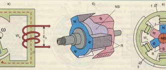
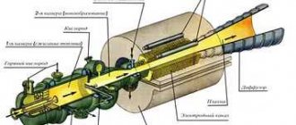
The no-load characteristic (x. x. x.) U = f (iв) at I = 0 and n = const determines the dependence of the voltage or electromotive force (emf) of the armature Ea on the excitation current during no-load (I = 0, P2 = 0). The characteristic is measured experimentally according to the diagram in Figure 1, and with the switch turned off.
Figure 1. Schemes of generators and motors of independent (a), parallel (b), series (c), mixed (d) excitation (solid arrows - current directions in generator mode, dashed - in motor mode)
| Figure 2. Idle characteristics of the independent excitation generator |
It is advisable to start taking the characteristics from the maximum value of the excitation current and the maximum voltage U = (1.15 – 1.25) Un (point a of the curve in Figure 2). As iв decreases, the voltage decreases along the descending branch of the ab characteristic, first slowly due to saturation of the magnetic circuit, and then faster. At iв = 0, the generator develops a certain voltage U00 = Vol (Figure 2), usually equal to 2 - 3% of Un, due to the residual magnetization of the poles and the yoke of the inductor. If you then change the excitation polarity and increase iв in the opposite direction, starting from iв = 0, then at some iв < 0 the voltage will drop to zero (point c, Figure 2), and then U will change sign and increase in absolute value along the вг branch X. X. X. When the current iв and voltage U reach the same absolute value at point g as at point a, we reduce the current iв to zero (point e), change its polarity and increase it again, starting from iв = 0. In this case, U changes along the branch dea x. X. X. As a result, let's return to point a characteristics. H. x. X. has the appearance of a narrow hysteresis loop due to the phenomenon of hysteresis in the magnetic circuit of the inductor.
When removing x. X. X. The current iв must be changed only in the direction indicated by the arrows in Figure 2, since otherwise the points will not fall on this hysteresis loop, but will be scattered.
Middle dashed x. X. X. in Figure 2 represents the calculated x. X. x., which on a certain scale repeats the magnetic characteristic of the generator, and from it the saturation coefficient of the machine kμ can be determined.
The idle speed characteristic makes it possible to judge the saturation of the machine’s magnetic circuit at rated voltage, to check the compliance of the calculated data with the experimental ones, and forms the basis for studying the operational properties of the machine.
§32. Generator circuits and their characteristics
The properties of a direct current generator are determined mainly by the method of switching on the field winding. Depending on this, generators are distinguished:
independently excited: the field winding is powered by an external DC source (a battery, a small auxiliary generator called an exciter, or a rectifier);
with parallel excitation: the excitation winding is connected in parallel to the armature winding and the load;
with series excitation: the excitation winding is connected in series with the armature winding and the load;
with mixed excitation: there are two excitation windings - parallel and serial; the first is connected in parallel to the armature winding, and the second is connected in series with it and the load.
Generators with parallel, series and mixed excitation are classified as self-excited machines, since their field windings are powered from the generator itself.
All of the listed generators have the same design and differ only in the design of the excitation windings. Windings of independent and parallel excitation are made of wire
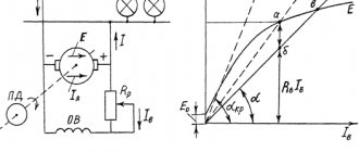
Rice. 120. Schematic diagram of a generator with independent excitation
small cross-section, they have a large number of turns, the series winding is made of large cross-section wire, it has a small number of turns.
The properties of DC generators are judged by their characteristics: idle, external and control. Below we will discuss these characteristics for generators of various types.
Generator with independent excitation. A characteristic feature of a generator with independent excitation (Fig. 120) is that its excitation current Iв does not depend on the armature current Iа, but is determined only by the voltage UB supplied to the excitation winding and the resistance RB of the excitation circuit. Typically, the excitation current is small and amounts to 2-5% of the rated armature current. To regulate the generator voltage, an adjusting rheostat Rрв is often included in the excitation winding circuit. On diesel locomotives, the current Iv is regulated by changing the voltage UB.
Characteristics of the idle speed of the generator (Fig. 121, a) - the dependence of the voltage U0 at idle on the excitation current Iв in the absence of load Rн, i.e. at In = Iа = 0 and at a constant speed n. At idle, when the load circuit is open, the generator voltage U0 is equal to its e. d.s. E0 = cEFn. Since when removing the idle speed characteristic, the rotation speed n is maintained unchanged, the voltage U0 depends only on the magnetic flux Ф. Therefore, the idle speed characteristic will be similar to the dependence of the flux Ф on the excitation current Iа (magnetic characteristic of the magnetic circuit of the generator). The no-load characteristic can be easily determined experimentally by gradually increasing the excitation current from zero to a value at which U0 ? 1.25 Unom, and then reducing the excitation current to zero. In this case, ascending 1 and descending 2 branches of the characteristic are obtained. The divergence of these branches is explained by the presence of hysteresis in the magnetic circuit of the machine. At Iв = 0, a residual e is induced in the armature winding by the flow of residual magnetism. d.s. Eost which is usually 2-4% of the rated voltage Unom.
At low excitation currents, the magnetic flux of the machine is small, therefore, in this region, the flux and voltage U0 change in direct proportion to the excitation current and the initial part of this characteristic is a straight line. As the excitation current increases, the magnetic circuit of the generator is saturated and the increase in voltage U0 slows down. The greater the excitation current becomes, the stronger the saturation of the machine’s magnetic circuit and the slower the voltage U0 increases. At very high excitation currents, the voltage U0 practically stops increasing.
The idle speed characteristic allows one to judge the value of the possible voltage and the magnetic properties of the machine. The rated voltage (indicated in the passport) for machines for general use corresponds to the saturated part of the characteristic (“knee” of this curve). In diesel locomotive generators that require voltage regulation over a wide range, both the curved and straight unsaturated part of the characteristic are used.
E.m.f. the machine changes in proportion to the rotation speed n, therefore, at n21, the idle speed characteristic lies below the curve for n1. When changing the direction of rotation of the generator, the direction of e changes. d.s. E induced in the armature winding, and therefore the polarity of the brushes.
The external characteristic of the generator (Fig. 121.6) is the dependence of the voltage U on the load current Iн = Iя at constant rotation speed n and excitation current Iв. The generator voltage U is always less than its e. d.s. E to the value of the voltage drop Iа? Rя in all windings connected in series to the armature circuit.
With an increase in the generator load (armature winding current Iа = Iн), the generator voltage decreases for two reasons: I) due to an increase in the voltage drop Iа? Rа in the armature winding circuit; 2) due to a decrease in e. d.s. E = cEFn as a result of the demagnetizing effect of the armature flux. As was established in § 29, the magnetic flux of the armature somewhat weakens the main magnetic flux F of the generator, which leads to a slight decrease in its e. d.s. E under load compared to e. d.s. E0 at idle.
The change in voltage during the transition from idle mode to rated load in the generator under consideration is 3-8% of U0.
If you close the external circuit to a very low resistance, that is, short-circuit the generator, then its voltage drops to zero. The current in the armature winding Ik during a short circuit will reach an unacceptable value, at which the armature winding may burn out. In low-power machines, the short-circuit current can be 10-15 times higher than the rated current; in high-power machines this ratio can reach 20-25.
Rice. 121. Characteristics of a generator with independent excitation: a - no-load; b - external; c - adjusting
Rice. 122. Schematic diagram of a generator with parallel excitation (a) and external characteristics of generators with independent and parallel excitation (b)
The regulating characteristic of the generator (Fig. 121, c) represents the dependence of the excitation current Iв on the load current Iн at a constant voltage U and rotation speed n. It shows how to regulate the excitation current in order to maintain a constant generator voltage when the load changes. Obviously, in this case, as the load increases, the excitation current must be increased.
The advantages of a generator with independent excitation are the ability to regulate voltage over a wide range from 0 to Umax by changing the excitation current and a small change in the generator voltage under load. However, it requires an external DC source to power the field winding.
Generator with parallel excitation. In this generator (Fig. 122, a) the armature winding current Iya branches into the external load circuit Rн (current Iн) and into the excitation winding (current Iв); current Iv for machines of medium and high power is 2-5% of the rated current value in the armature winding. The machine uses the principle of self-excitation, in which the excitation winding receives power directly from the armature winding of the generator. However, self-excitation of the generator is possible only if a number of conditions are met.
1. To begin the process of self-excitation of the generator, it is necessary to have a flow of residual magnetism in the magnetic circuit of the machine, which induces e in the armature winding. d.s. Erest. This e. d.s. ensures the flow of some initial current through the “armature winding - field winding” circuit.
2. The magnetic flux generated by the field winding must be directed in accordance with the magnetic flux of residual magnetism. In this case, during the process of self-excitation, the excitation current Iв and, consequently, the magnetic flux F of the machine e will increase. d.s. E. This will continue until, due to saturation of the magnetic circuit of the machine, the further increase in F, and therefore E and Iv, stops. Coincidence in the direction of the indicated flows is ensured by correctly connecting the field winding to the armature winding. If it is connected incorrectly, the machine demagnetizes (residual magnetism disappears) and e.g. d.s. E decreases to zero.
3. The excitation circuit resistance RB must be less than a certain limit value called critical resistance. Therefore, to quickly excite the generator, it is recommended that when the generator is put into operation, the adjusting rheostat Rрв, connected in series with the excitation winding, is completely removed (see Fig. 122, a). This condition also limits the possible range of regulation of the excitation current, and therefore the voltage of the generator with parallel excitation. Typically, it is possible to reduce the generator voltage by increasing the resistance of the field winding circuit only up to (0.6-0.7) Unom
It should be noted that for self-excitation of the generator it is necessary that the process of increasing its e. d.s. E and excitation current Iв occurred when the machine was operating in idle mode. Otherwise, due to the small value of Erest and the large internal voltage drop in the armature winding circuit, the voltage supplied to the field winding may decrease almost to zero and the field current will not be able to increase. Therefore, the load should be connected to the generator only after a voltage close to the rated voltage has been established at its terminals.
When the direction of rotation of the armature changes, the polarity of the brushes changes, and therefore the direction of the current in the field winding; in this case, the generator is demagnetized.
To avoid this, when changing the direction of rotation, it is necessary to switch the wires connecting the field winding to the armature winding.
The external characteristic of the generator (curve 1 in Fig. 122, b) is the dependence of the voltage U on the load current Iн at constant values of the rotation speed n and the excitation circuit resistance RB. It is located below the external characteristic of the generator with independent excitation (curve 2). This is explained by the fact that in addition to the same two reasons that cause a decrease in voltage with increasing load in a generator with independent excitation (voltage drop in the armature circuit and the demagnetizing effect of the armature reaction), in the generator under consideration there is a third reason - a decrease in the excitation current. Since the excitation current IB = U/RB, i.e., depends on the voltage U of the machine, then with a decrease in voltage for the above two reasons, the magnetic flux Ф and e decreases. d.s. generator E, which leads to an additional decrease in voltage. The maximum current Icr corresponding to point a is called critical. When the armature winding is short-circuited, the current Ik of the generator with parallel excitation is small (point b), since in this mode the voltage and excitation current are zero. Therefore, the short circuit current is created only by e. d.s. from residual magnetism and is (0.4 -0.8) Inom. The external characteristic by point a is divided into two parts: the upper - working and the lower - non-working. Usually, not the entire working part is used, but only a certain segment of it. Work on the section ab of the external characteristic is unstable; in this case, the machine goes into the mode corresponding to point b, i.e. into the short circuit mode.
The no-load characteristic of a generator with parallel excitation is taken with independent excitation (when the armature current Iа = 0), so it is no different from the corresponding characteristic for a generator with independent excitation (see Fig. 121, a). The regulating characteristic of a generator with parallel excitation has the same form as the characteristic for a generator with independent excitation (see Fig. 121, c).
Generators with parallel excitation are used to power electrical consumers in passenger cars, cars and airplanes, as control generators on electric locomotives, diesel locomotives and motor cars, and to charge batteries.
Generator with series excitation. For this generator (Fig. 123, a) the excitation current Iв is equal to the load current Iн = Iя and the voltage changes greatly when the load current changes. When idling, a small e is induced in the generator. d.s. Eost created by the flow of residual magnetism (Fig. 123, b). With increasing load current Iн = Iв = Iя, the magnetic flux, e, increases. d.s. and generator voltage; this increase, like that of other self-excited machines (generator with parallel excitation), continues to a certain limit due to the magnetic saturation of the machine. When the load current increases above Icr, the generator voltage begins to decrease, since the excitation magnetic flux almost stops increasing due to saturation, and the demagnetizing effect of the armature reaction and the voltage drop in the armature winding circuit Iа? Rа continue to increase. Typically, the current Icr is significantly greater than the rated current. The generator can operate stably only on part ab of the external characteristic, i.e. at load currents greater than the rated one.
Since in series-excited generators the voltage changes greatly when the load changes, and is close to zero at idle, they are unsuitable for powering most electrical consumers. They are used only for electrical (rheostatic) braking of engines with sequential excitation, which are then transferred to generator mode.
Generator with mixed excitation. In this generator (Fig. 124, a) most often the parallel excitation winding is the main one, and the series one is the auxiliary one. Both windings are located on the same poles and are connected so that the magnetic fluxes they create are added (with consonant switching) or subtracted (with counter switching).
A generator with mixed excitation, when its excitation windings are switched on accordingly, allows one to obtain an approximately constant voltage when the load changes. The external characteristic of the generator (Fig. 124, b) can be, to a first approximation, presented as the sum of the characteristics created by each
Rice. 123. Schematic diagram of a generator with sequential excitation (a) and its external characteristics (b)
Rice. 124. Schematic diagram of a generator with mixed excitation (a) and its external characteristics (b)
excitation winding. When only one parallel winding is turned on, through which the excitation current Iв1 passes, the generator voltage U gradually decreases with increasing load current Iн (curve 1). When one series winding is turned on, through which the excitation current Iв2 = Iн passes, the voltage U increases with increasing current Iн (curve 2). If you select the number of turns of the series winding so that, at a rated load, the voltage ΔUlast created by it compensates for the total voltage drop ΔU when the machine operates with only one parallel winding, then it is possible to achieve that the voltage U when the load current changes from zero to the rated value remains almost unchanged (curve 3). In practice, it varies within 2-3%. By increasing the number of turns of the series winding, it is possible to obtain a characteristic in which the voltage Unom will be greater than the voltage U0 at no-load (curve 4); This characteristic provides compensation for the voltage drop not only in the internal resistance of the generator armature circuit, but also in the line connecting it to the load. If the series winding is turned on so that the magnetic flux it creates is directed against the flow of the parallel winding (counter connection), then the external characteristic of the generator with a large number of turns of the series winding will drop steeply (curve 5).
Back-to-back connection of series and parallel excitation windings is used in welding generators operating under conditions of frequent short circuits. In such generators, during a short circuit, the series winding almost completely demagnetizes the machine and reduces the short-circuit current. to a value safe for the generator. Generators with back-to-back excitation windings are used on some diesel locomotives as exciters for traction generators; they ensure constant power output from the generator. Such exciters are also used on DC electric locomotives. They power the field windings of traction motors, which operate in generator mode during regenerative braking, and provide steep external characteristics (see § 37).
Short circuit characteristic
| Figure 3. Short circuit characteristics of the independent excitation generator |
The short circuit characteristic (short circuit) I = f (iв) at U = 0 and n = const is removed when the output terminals of the generator armature circuit are short-circuited. Since U = 0, then, according to the expression
(voltage equation U at the generator terminals), Ea = Ia × Ra and since Ra is small, then under the experimental conditions e. d.s. Ea should also be small. Therefore, it is necessary to exercise caution and begin removing x. k.z. from the minimum values of iв so that the armature current does not receive an unacceptably large value. Usually they remove x. k.z. up to I = (1.25 – 1.5) In. Since when removing x. k.z. the electromotive force is small and therefore the flow is small and the machine is not saturated, then the dependence I = f (iв) is almost linear (Figure 3). When iв = 0, due to the presence of residual magnetic flux, the current I is not equal to 0 and in large machines is close to the rated value and even greater than it. Therefore, before removing x. k.z. It is advisable to demagnetize such a machine by feeding the excitation winding at idle speed with such an excitation current in the opposite direction, at which U = 0. In a demagnetized machine x. k.z. starts from zero (dashed line in Figure 3) If x. k.z. removed without first demagnetizing the machine (solid line in Figure 3), then it is also advisable to move it parallel to itself to the origin of coordinates (dashed line in Figure 3).
Classification
There are two types of DC generators:
- with independent excitation of windings;
- with self-excitation.
To self-excite generators, they use electricity generated by the device itself. Based on the principle of connecting the armature windings, self-excited alternators are divided into types:
- devices with parallel excitation;
- alternators with series excitation;
- mixed type devices (composite generators).
Let us consider in more detail the features of each type of connection of armature windings.
With parallel excitation
To ensure normal operation of electrical appliances, a stable voltage is required at the generator terminals, independent of changes in the total load. The problem is solved by adjusting the excitation parameters. In alternators with parallel excitation, the coil leads are connected through a control rheostat in parallel to the armature winding.
Excitation rheostats can short-circuit the winding to themselves. If this is not done, then when the excitation circuit breaks, the self-induction EMF in the winding will sharply increase, which can break through the insulation. In a short circuit condition, energy is dissipated as heat, preventing destruction of the generator.
Electric machines with parallel excitation do not require an external power source. Due to the presence of residual magnetism, which is always present in the core of the electromagnet, self-excitation of parallel windings occurs. To increase residual magnetism in field coils, electromagnet cores are made of cast steel.
The self-excitation process continues until the current reaches its maximum value and the EMF reaches its nominal values at optimal rotation speed of the armature.
Advantage: generators with parallel excitation are weakly affected by short-circuit currents.
With independent excitation
Batteries or other external devices are often used as a power source for field windings. Models of low-power machines use permanent magnets, which ensure the presence of the main magnetic flux.
On the shaft of powerful generators there is an exciter generator that produces direct current to excite the main armature windings. For excitation, 1–3% of the rated armature current is sufficient and does not depend on it. The EMF is changed by a control rheostat.
The advantage of independent excitation is that the excitation current is not affected in any way by the terminal voltage. And this ensures good external characteristics of the alternator.
With sequential excitation
The series windings produce a current equal to the generator current. Since the load is zero at idle, the excitation is zero. This means that the idle speed characteristic cannot be removed, that is, there are no adjustment characteristics.
In generators with series excitation there is practically no current when the rotor rotates at idle speed. To start the excitation process, it is necessary to connect an external load to the generator terminals. This pronounced dependence of voltage on load is a disadvantage of series windings. Such devices can only be used to power electrical appliances with a constant load.
With mixed excitement
Useful characteristics combine the designs of generators with mixed excitation. Their features: the devices have two coils - the main one, connected in parallel to the armature windings, and the auxiliary one, which is connected in series. A rheostat is included in the parallel winding circuit, which is used to regulate the excitation current.
The process of self-excitation of an alternator with mixed excitation is similar to that of a generator with parallel windings (due to the absence of an initial current, the series winding does not participate in self-excitation). The no-load characteristic is the same as that of an alternator with parallel winding. This allows you to regulate the voltage at the generator terminals.
Mixed excitation smoothes out voltage ripple at rated load. This is the main advantage of such alternators over other types of generators. The disadvantage is the complexity of the design, which leads to an increase in the cost of these devices. Such generators do not tolerate short circuits.
Characteristic (reactive) triangle
The characteristic (reaction) triangle determines the reaction of the armature and the voltage drop in the armature circuit. It is constructed to find the armature reaction from experimental data and is also used to construct some characteristics of the machine if they cannot be determined experimentally. The characteristic triangle can be constructed from experimental data using x. X. X. and any other main characteristics of the machine, as well as according to calculated data. Let us consider here its construction using x. X. X. their. k.z., for which we turn to Figure 4, where x is shown. k.z. I = f (iв) (straight line 1) and the initial, straight-line part x. X. X. U = f (iв) (line 2), passing through the origin.
Let's construct a characteristic triangle for the rated current of the machine Ia = I = In, which is x. k.z. corresponds to point a and point b on the abscissa axis (Figure 4, a). Let's construct a segment bv on straight line ab, equal on the scale of line 2 to the voltage drop in the armature circuit Iн × Ra, and connect a point in the horizontal line with point r on x. X. X. Then triangle bvg will be a characteristic triangle. The horizontal leg rg of this triangle represents the magnetizing force of the armature reaction on the scale of the excitation current, which can be proven as follows.
| Figure 4. Construction of the characteristic triangle in the case of demagnetizing (a) and magnetizing (b) armature reaction |
Section 0b in Figure 4, a is equal to the current iв required to obtain current I = In during a short circuit. In this case, e must be induced in the armature. d.s. Ea = Iн × Ra, equal to the segment gd, which requires an excitation current 0d = iе at no-load. Thus, the difference 0b - 0d = db = iva between the actual current iv = 0b during a short circuit and the current iе = 0d during no-load can only be due to the influence of the current in the armature and should therefore express the magnetizing reaction force of the armature on the scale of the excitation current iв .
Figure 4, a corresponds to the case of a demagnetizing reaction of the armature (iа is greater than 0), and Figure 4, b – to the case of a magnetizing reaction of the armature (iа is less than 0). In the latter case x. the short circuit, naturally, should rise steeper. For other values of armature currents (I ≠ Iн), the legs of the triangle bvg change almost proportionally to the armature current, since the nonlinearity of the brush contact resistance has little effect.
Since under the conditions of removing x. k.z. Since the magnetic circuit of the machine is not saturated, the characteristic triangle constructed in this way takes into account only the longitudinal reaction of the armature, caused by a random or deliberate shift of the brushes from the geometric neutral and the deviation of the commutation from the rectilinear one. When installing brushes on a geometric neutral, the leg of the triangle iva = db is equal to the magnetizing force of the switching reaction of the armature (on a scale iv) and characterizes the quality of commutation (in Figure 4, a - slow commutation and in Figure 4, b - accelerated). When the brushes are in neutral and the commutation is rectilinear, iva = db = 0 and the triangle bvg degenerates into a vertical straight line.
To construct a characteristic triangle taking into account the influence of the transverse reaction of the armature, you can use x. X. X. and external, adjustment or load characteristics. Usually the load characteristic is used.
External characteristics of the generator
The external characteristic of the independent excitation generator U = f (I) with iв = const and n = const (Figure 5) determines the dependence of the generator voltage on its load under natural conditions, when the excitation current is not regulated. As I increases, the voltage U drops slightly for two reasons: due to the voltage drop in the armature circuit I × Ra and a decrease in e. d.s. Ea due to a decrease in flow under the influence of the transverse reaction of the armature (with brushes at the geometric neutral). With a further increase in I, the voltage will begin to fall faster, since under the influence of the armature reaction the flux decreases and the operating point shifts to a steeper falling section of the machine’s magnetization curve.
| Figure 5. External characteristics of the independent excitation generator |
It is recommended to take the external characteristic at such an excitation (iв = iвн), when at I = Iн also U = Un (nominal mode). When switching to idle (I = 0), in this case the voltage increases by a very specific amount ΔUn (Figure 5), which is called the nominal change in generator voltage . In independent excitation generators
The external characteristic (in the left quadrant of Figure 6) can also be constructed using x. X. X. (in the right quadrant of Figure 6) and the characteristic triangle. To do this, let us draw a vertical straight line ab in Figure 6, corresponding to the given current iв = const. Then ab =0b represents U at I = 0 and determines the starting point of the external characteristic.
Let us then place in Figure 6 the characteristic triangle where, constructed on the appropriate scales for I = In, so that its vertex r lies on x. X. x., and leg de – on straight ab. Then the segment ae = zhz will be equal to U for I = In, which can be proven as follows. If U = ae, then Ea = U + In × Ra = ae + ed = ad = ur and to create such an e. d.s. at idle, the excitation current required is ive = 0u. When under load, the excitation current must be increased by the amount iva = gd = ia to compensate for the demagnetizing reaction of the armature. The required total excitation current in this case iв = iе + iа = 0у + яа = 0а exactly corresponds to the given one, which was what needed to be proven.
If we accept that the legs, and therefore the hypotenuse of the characteristic triangle, change in proportion to I, then to obtain other points of the external characteristic it is enough to draw in Figure 6 between x. X. X. and straight line ab inclined segments of straight lines (hypotenuse of new characteristic triangles), parallel to the hypotenuse ge. Then the lower points of these segments (on straight line ab) will determine the value of U at currents
and so on.
By moving these points horizontally to the left quadrant of Figure 6 for the corresponding values of I and connecting them with a smooth curve, we obtain the desired external characteristic U = f (I).
| Figure 6. Construction of the external characteristic of an independent excitation generator using the no-load characteristic and the characteristic triangle |
In fact, the horizontal leg of the characteristic triangle does not grow in proportion to I as U decreases. Therefore, the real external characteristic deviates somewhat to the side from the constructed one, as shown in the left quadrant of Figure 6 by the dashed line.
The external characteristic point with U = 0 determines the value of the short circuit current of the machine when fully excited. Since Ra is small, this current is 5–15 times higher than In. Such a short circuit is very dangerous, as a circular fire occurs, as well as large mechanical forces and torques. Therefore, under operating conditions, generators and engines of medium and high power are protected by high-speed automatic switches in the armature circuit, which limit the duration of the short circuit and disconnect the machine from the network within 0.01 - 0.05 s after the start of a sudden short circuit. However, these switches do not protect the machine if there is a short circuit inside the machine.
If there are experienced x. X. X. and external characteristic and if Ra is known, then by constructing in Figure 6 in the reverse order, one can obtain characteristic triangles taking into account real saturation conditions for any values of U and Ea.
| DC Generator Equation |
| Generator characteristics |
| Parallel operation of DC generators |
Page 4 of 5
GENERATOR CHARACTERISTICS
The operating properties of electrical machines are determined by their characteristics. For DC generators, the main characteristics are the no-load characteristics; load, external and adjustment characteristics.
All specified characteristics are determined at a constant rated armature rotation speed. They can be obtained both experimentally and by calculation.
CHARACTERISTICS OF AN INDEPENDENTLY EXCITED GENERATOR
In Fig. 1a shows a diagram for an experimental study of an independent excitation generator. To make it possible to change the current I , the excitation winding is connected to an independent source through a variable resistor R in . The current in the armature circuit I a is regulated by a variable resistor R ng .
The measurement limits of the ammeter and voltmeter in the armature circuit should be selected based on the rated values of current I nom and voltage U nom , which are indicated on the machine plate attached to its frame. The ammeter in the field winding circuit is selected for a current equal to 1-5% I nom .
Characteristics of idle speed. The no-load characteristic represents the dependence of the EMF at the terminals of the generator E on the excitation current I in with the armature circuit open (switch QS is turned off, current I a = 0). In the general case, when the excitation current changes first in one direction and then in the other, this dependence, plotted in four quadrants, has the form of a loop shown in Fig. 3. The discrepancy between the curves obtained by increasing and decreasing the excitation current is explained by the presence of hysteresis in the steel from which the magnetic system of the machine is made. The average curve is taken as the calculated one (shown by the dashed line in Fig. 3). When I in = 0, EMF Erest is induced in the armature winding. This EMF is created by the residual magnetism field of the stator and is called the EMF of residual magnetism. The value of Erest is approximately equal to 1-3% of the rated voltage of the machine.
For practical purposes, we usually limit ourselves to removing part of the loop, which is obtained by reducing the current I in from the maximum value to zero (Fig. 4).
Continuing the resulting curve 1 until it intersects the x-axis at point A, and then moving it parallel to itself to the right at a distance OA, we obtain the calculated idle speed characteristic 2. When taking the idle speed characteristic, you should pay attention to the fact that the excitation current changes in one direction (or only increased, or only decreased), since otherwise there will be a large scatter of points due to the fact that they will fall on different hysteresis curves.
In the initial part of the no-load characteristics, the EMF changes in proportion to the excitation current, and then the growth of the EMF slows down, which is explained by the saturation of the steel sections of the magnetic circuit.
The practical significance of the idle speed characteristic is that it can be used to judge the degree of saturation of the machine’s magnetic circuit. In addition, this characteristic is necessary for constructing other characteristics of the machine.
Load characteristic. This characteristic represents the dependence of the voltage at the terminals of the machine U on the excitation current I in, provided that the current in the armature circuit I a is maintained constant. The practical significance of the load characteristic is that it allows one to quantify the demagnetizing effect of the armature reaction and study the dependence of this reaction on the saturation of the magnetic circuit of the machine and the armature current.
You can remove a number of load characteristics for different values of current Ia . If one load characteristic is taken, then it is most often assumed that I a = I nom . The excitation current is changed towards a decrease, starting from its maximum value.
For comparison and further construction, it is convenient to plot the load characteristic on the same graph with the descending idle characteristic (Fig. 5). The idle characteristic can be considered as a special case of the load characteristic at I a = 0 (curve 1 in Fig. 5).
The load characteristic is located below the no-load characteristic due to the voltage drop in the armature circuit and the demagnetizing effect of the armature reaction, which reduces the magnetic flux and emf of the machine (curve 2 in Fig. 5).
The component of the armature reaction that affects the magnetic flux and emf of the machine can be found as follows. By adding the voltage drop in the armature circuit IaRa , we obtain the dependence of the EMF induced in the armature winding under load on the excitation current (dashed curve in Fig. 5; current Ia is equal to the current at which the load characteristic was taken). This dependence is usually located below the idle speed characteristic.
To obtain the same EMF E' at idle, an excitation current I in1 is required, and at load - a current I in2. The difference in these currents goes to compensate for the demagnetizing effect of the armature reaction. The segment bd corresponds to a decrease in the magnetic flux and EMF induced in the armature winding.
In the general case, the difference I in2 - I in1 is proportional to the algebraic sum of the demagnetizing component of the transverse reaction of the armature F in, qd and the longitudinal MMF of the armature F d. If the brushes are located at the geometric neutral, then we can consider
| I in2 - I in1 ≈ F in,qd /ω in= I in,qd., |
where ω in is the number of turns of the field winding coil.
By connecting points a, b and c, we obtain a triangle called the characteristic triangle. The horizontal leg bc of this triangle is equal to I in,qd, and the vertical ab is equal to IaRa . The characteristic triangle is used to construct other characteristics of the machine. In this case, it is approximately assumed that both of its legs change in proportion to the current Ia .. A more accurate dependence I in, qd on the current Ia can be obtained by taking a series of load characteristics at different currents Ia , and then for each of them at I in = const determine I in,qd.
If you construct characteristic triangles at different currents Iv , then you can identify the effect of saturation of the magnetic circuit on the value of Iv ,qd. As saturation decreases (current Ia ), the demagnetizing effect of the transverse reaction of the armature (leg bc) decreases.
External characteristics. This characteristic is the main operating characteristic of the generator. It shows how the voltage at the terminals of the machine U I = I increases , if there is no effect on the excitation circuit. For an independent excitation generator, the external characteristic U = f ( I ) is removed at I ==const.
The starting point for taking the external characteristic is the point when, at the rated load current I = I U is set at the generator outputs (Fig. 6). The voltage is changed by adjusting the excitation current Iv , and the current I is changed by adjusting the resistance of the resistor R ng (Fig. 1, a).
The excitation current corresponding to U = U nom at I = I nom is called the rated excitation current I in nom. During the process of taking the external characteristic, this current is maintained constant. Starting from the starting point, the load current gradually decreases to zero. In this case, the generator voltage increases, since as the current Ia , the voltage drop in the armature circuit and the demagnetizing effect of the armature reaction decrease. At idle U=U0 (Fig. 6).
The external characteristic determines the change in voltage Δ U. Usually it is expressed as a percentage of the rated voltage:
| Δ U %= ( (U0.- U nom )/U nom )*100 , | (9) |
The change in voltage Δ U for independent excitation generators is 10-15%• In Fig. 7. The external characteristic of the independent excitation generator is shown when the load changes from idle mode to short circuit mode. The short circuit current I k for such generators is 5-10 I nom.
Regulating characteristic. As follows from considering the external characteristics of the independent excitation generator, when I V = const, the voltage at the generator terminals does not remain constant with a change in load. In order to keep the voltage constant, it is necessary to regulate the excitation current. The law for regulating the excitation current in order to maintain a constant voltage when the load changes is given by the regulation characteristic, which is the dependence I in = f ( I ) at U = U nom = const . The adjustment characteristic is shown in Fig. 8. They begin to remove it in idle mode, when I = 0. With an increase in the load current, the excitation current I in must be increased slightly to compensate for the decrease in voltage due to the voltage drop and the demagnetizing effect of the armature reaction.
CHARACTERISTICS OF PARALLEL EXCITATION GENERATOR
Self-excitation of the generator. In a parallel excitation generator, the excitation winding is powered by its own armature (Fig. 1,b). The electromotive force in the armature appears as a result of self-excitation of the machine, which occurs under the influence of residual magnetism in the poles and yoke of the stator. In order for a magnetic flux of residual magnetism to appear in a machine, it must be magnetized at least once by passing current through the excitation winding or an external source.
The self-excitation process proceeds as follows. The magnetic flux of residual magnetism in the winding of a rotating armature induces an emf. This EMF (EMF of residual magnetism E rest) is small and amounts to 1-3% of the rated voltage of the machine. Since the excitation winding is connected to the armature, the emf E ref creates a small current in it. This current, flowing through the field winding, increases the magnetic flux of the poles, which in turn increases the EMF in the armature. An increase in EMF causes an increase in the current in the field winding, which further increases the magnetic flux of the poles and the EMF induced in the armature, which causes a further increase in the field current, etc. The process of current increase in the excitation winding during idling of the machine ( I = 0 ) can be described by the differential equation
| e = i in Σ R in + d ( L in i in )/ dt , | (10) |
where L in is the inductance of the excitation winding; Σ R in is the total resistance of the circuit of this winding, including the resistance of the adjusting resistor.
The voltage drop in the armature circuit from current i in is negligible, therefore in (10) the voltage at the terminals of the excitation winding is taken to be equal to the EMF.
The self-excitation process will end when the current in the field winding reaches a steady value.
Then d(L in i in )/dt = 0;
| E = I in Σ R in. | (11) |
In Fig. Figure 9 shows the dependences E = f ( I in ) and I in Σ R in = f ( I in ) for n = const. The first dependence is the characteristic of the idle circuit (curve 1), and the second is the characteristic of the excitation circuit.
If we assume that Σ R in = const , then the characteristic of the excitation circuit is a straight line (2 in Fig. 9), going at an angle α to the abscissa axis, and tg α = I in Σ R in / I in = . Σ R c. The intersection point of the characteristics (point A) corresponds to equality (11), and the emf E corresponding to this point is the emf that will be established at a given resistance Σ R at the terminals of the machine. When Σ R E will change . If you increase the resistance Σ R in, then the slope angle of the excitation circuit characteristic a will increase, and point A will move to the left. At a certain excitation circuit resistance R in, kr, called critical, straight line I in R in, kr coincides with the straight-line part of the idle characteristics (straight 3). The critical resistance is the maximum resistance of the field winding circuit at which self-excitation of the machine is possible. With a further increase in resistance Σ R in, self-excitation will not occur, since straight line I in Σ R in = f ( I in ) in this case does not intersect the idle characteristic (straight 4).
If the generator operates with a variable rotation speed n, then each rotation speed will have its own idle characteristic E = f ( I in ) , since E is proportional to n (curves 1-3 in Fig. 10). In accordance with this, for each rotation speed there will be a different value of the critical resistance R in, cr. For each resistance Σ R in there is a critical value of the rotation speed, below which self-excitation is impossible (curve 2 in Fig. 10).
Self-excitation of the generator occurs if the current Iv flowing through the excitation winding creates a magnetic flux directed in accordance with the flow of residual magnetism. If the excitation winding is turned on incorrectly, these flows will be directed in the opposite direction and self-excitation will not occur. Then, to change the direction of current I in the field winding, the ends of the supply conductors connecting the field winding to the armature should be swapped.
From the above it follows that for self-excitation of the generator it is necessary that there is a residual magnetic flux, that the resistance of the field winding circuit is less than critical and that the field winding is correctly connected to the armature.
Idle and load characteristics. In contrast to the independent excitation generator, the parallel excitation generator has armature current I a not equal to load current I (see Fig. 1, b). When the load is disconnected ( I = 0 ), the armature current is not zero and will be equal to I V.
The idle and load characteristics are measured for the parallel excitation generator in the same way as for the independent excitation generator, and have the same character. the current I in is reduced using a variable resistor R in from the highest to the smallest possible value. The electromotive force of residual magnetism is determined when the field winding is disconnected.
Due to the small value of the excitation current Iv , the voltage drop it causes in the armature circuit is small and does not have a significant effect on the machine voltage under load. At idle, it can be assumed that the voltage at the terminals is almost equal to the armature EMF.
External characteristics. The external characteristic U = f ( I ) is removed provided that Σ R in = const . Using a variable resistor R , the resistance Σ R in is set so that at the rated load current I rated, the voltage at the terminals of the machine is rated. The load current is set with a variable resistor R ng. Then, by changing the current I , other points of the external characteristic are obtained (Fig. 11). As follows from Fig. 11, with increasing current I, voltage U decreases.
The decrease in voltage U at the terminals of the parallel excitation generator with increasing current I is more pronounced than at the terminals of the independent excitation generator operating at Iv = const . In a parallel excitation generator, the voltage decreases not only due to the demagnetizing effect of the armature reaction and the voltage drop in the armature circuit, but also due to a decrease in the excitation current Iv . The decrease in excitation current I in = U / Σ R at Σ R in = const is caused by a decrease in voltage U at the terminals of the machine to which the excitation winding circuit is connected.
In a parallel excitation generator, as the load resistance decreases, the current I will increase to a certain value, called the critical current I cr (Fig. 11). The critical current is 1.5-2.5 I nom. With a further decrease in load resistance, the current I begins to decrease. This nature of the external characteristic is explained by the fact that the parallel excitation generator demagnetizes itself, as the excitation current decreases. At first, this process proceeds slowly, since the steel of the machine is saturated and a decrease in the excitation current does not cause a strong decrease in the magnetic flux and emf of the machine. Then, when the excitation current corresponds to the linear (unsaturated) part of the no-load characteristic, demagnetization will occur more intensely, since a decrease in the current Iv will cause large changes in the magnetic flux and EMF. In the event of a short circuit, the machine will practically be demagnetized and the steady-state short circuit current I is determined only by the EMF of residual magnetism. Due to the smallness of this EMF, the current Ik in most cases is small and does not exceed the nominal value. However, despite this, in the transient mode, during a sudden short circuit due to a slow decrease in the magnetic flux and EMF, the short circuit current can exceed the rated value several times, which will cause strong sparking of the brushes, and in some cases the appearance of a circular fire. Therefore, these generators, like all other generators, must be equipped with fuses or high-speed circuit breakers to interrupt the short-circuited circuit before the armature current reaches large values. The change in voltage of the parallel excitation generator, determined by (9), is 15-20%.
Regulating characteristics of the parallel excitation generator. The control characteristic I in = f ( I ) of the parallel excitation generator at U = U nom = const has the same character as for the independent excitation generator. For the same generator, the adjustment characteristics obtained with independent power supply of the excitation winding and with its parallel connection will be the same.
CHARACTERISTICS OF SERIES EXCITATION GENERATOR
For series excitation generators, the excitation current Iv is equal to the armature current Ia . Therefore, at no-load, when I in = I a = I = 0 , the EMF induced in the armature winding is equal to E rest.
The no-load and load characteristics for such a generator can be measured when the winding is powered from an independent source. These characteristics have the same form as for the independent excitation generator (see Fig. 5).
Self-excitation of the generator occurs if the armature circuit resistance is less than critical. The external characteristics of the generator are shown in Fig. 12 (curve 2). The same figure shows the idle speed characteristic E = f ( I in ) (curve 1). At the same current Iv = I , the generator voltage is less than the EMF according to the no-load characteristic, due to the voltage drop in the armature circuit and the demagnetizing effect of the armature reaction.
At low loads, when the armature current and, consequently, the excitation current are small, the magnetic system of the machine is unsaturated and its EMF changes in proportion to the current I. effect of the armature reaction practically also change in proportion to the current I. Therefore, the voltage at the machine terminals increases in proportion to the current I. At high currents, the magnetic system of the machine becomes saturated, as a result of which the EMF will change little I Therefore, the voltage increases slightly with increasing load current, and at very high load currents, due to the voltage drop and the demagnetizing effect of the armature reaction, it begins to decrease.
Due to the strong dependence of voltage on load current, series excitation generators have not found wide practical application.
CHARACTERISTICS OF MIXED EXCITATION GENERATOR
The circuit of the mixed excitation generator is shown in Fig. 1, g. The parallel (shunt) excitation winding OVSh can be connected to the armature circuit before the serial (serial) winding OVS (as shown in the figure) or after it (the conductor of the OVSh winding is transferred from point D2 to point C2). The characteristics of the generator with both connection methods will be almost the same, since the series winding has low resistance and the voltage drop in it will be small. Iv through it is also negligible due to the small number of its turns and the relatively small current Iv .
Self-excitation of the generator occurs in the same way as a parallel excitation generator. The armature current is equal to I a = I + I v.
The greatest practical application is found in generators with matched excitation windings. The largest share of the excitation MMF is created by the parallel winding of the OVSh. The series winding is calculated so that its MMF is slightly higher than the MMF of the demagnetizing component of the armature reaction F in, qd In this case, the series winding will not only compensate for the demagnetizing component of the armature reaction, but will also create an excess MMF, which will increase the excitation magnetic flux and the armature EMF with increasing current loads. As a result of the biasing effect of the series winding, the generator voltage will increase with increasing I , as can be seen in the external characteristic U = f ( I ) at Σ R in = const , shown in Fig. 13. The level of increase in generator voltage with increasing current I depends on the number of turns of the series winding.
The winding can be designed so that the voltage increases by the amount necessary to compensate for the voltage drop in the wires running from the generator to the consumer. Then the consumer's voltage will be automatically maintained approximately constant under any load.
With a weak series winding, the external characteristic has a falling character. Note that the effectiveness of the series winding depends on the saturation of the magnetic circuit of the machine. The magnetomotive force of a series winding with strong saturation will give a slight increase in magnetic flux and EMF, therefore, even with a sufficiently strong winding or with heavy loads, the voltage at the machine terminals will decrease with increasing load current.
The idle characteristics and load characteristics of the mixed excitation generator are measured in the same way as for the parallel excitation generator and have the same character.
Depending on the relationship between the MMF of the series (serial) field winding F c and the demagnetizing component of the armature reaction F in, qd, the load characteristic can be located either above or below the no-load characteristic. With a sufficiently strong series winding, the load characteristic (curve 2) is higher than the no-load characteristic (curve 1) (Fig. 14). If we construct a characteristic triangle based on these characteristics, then its horizontal leg bс will be proportional to the resulting magnetizing MMF created by the armature current along the axis of the excitation winding. The value of this leg on the excitation current scale is equal to ( F c - F in, qd) / ω in.
The triangle thus obtained is used to construct characteristics.
Regulating characteristic. The characteristic I in = f ( I ) at U = const for a mixed excitation generator depends on the type of external characteristic. With a sufficiently strong series excitation winding, when the generator voltage increases with increasing load current, the adjustment characteristic has the form shown in Fig. 15.
Mixed excitation generators with windings connected in opposite directions are used relatively rarely. For these generators, the series winding will create an MMF directed in the same way as the MMF of the demagnetizing component of the armature reaction. Under their combined demagnetizing effect, the resulting magnetic excitation flux of the machine will decrease with increasing load current. As a result, the external characteristic of such a generator will have a sharp decline (Fig. 16). The adjustment characteristic is shown in Fig. 17.
COMPARISON OF GENERATOR CHARACTERISTICS
If the external and adjustment characteristics of the same generator are taken with different circuits for connecting its excitation windings, then the obtained characteristics will be located relative to each other as shown in Fig. 18 and 19.
The greatest change in voltage will be for mixed excitation generators when the windings are switched on in opposite directions, and the smallest for mixed excitation generators when the windings are switched on concordantly.
Mixed excitation generators with harmonious connection of windings and parallel excitation are used in converter installations as autonomous sources of direct current.
Mixed excitation generators are preferred to be used in cases where frequent and sudden changes in load occur, since they can provide automatic voltage maintenance. Independent excitation generators are used when it is necessary to vary the voltage within a wide range. In particular, they are used in electric drives to power single motors with a wide range of speed control.
« Prev. - Next. »
Regulating characteristic
The regulation characteristic iв = f (I) with U = const and n = const shows how the excitation current needs to be adjusted so that the generator voltage does not change when the load changes (Figure 7). With an increase in I, the current iв must be increased slightly in order to compensate for the influence of the voltage drop Ia × Ra and the armature reaction.
| Figure 7. Regulating characteristic of an independent excitation generator |
When moving from no-load with U = Un to the rated load I = In, the increase in excitation current is 15 - 25%.
The construction of the control characteristic (the lower quadrant of the figure according to x. x. x. (the upper quadrant of the figure and the characteristic triangle) is carried out as follows. For a given U = 0a = vb = const, the value of iв at I = 0 is determined by point b. The characteristic triangle where for the rated current Let us arrange it so that its vertices r and e are respectively on x.x.x. and straight line abe.Then the segment 0zh = ae determines the value of iв for I = In, which can be proven in the same way as was done in the case of constructing an external characteristic. To obtain other points of the characteristic, it is enough to draw line segments parallel to the hypotenuse r between the curve x. x. hypotenuse ge, as in the previous case. By moving these points vertically down, to the lower quadrant of Figure 8, to the level of the corresponding values of I, we obtain the points of the adjustment characteristic. Taking into account the changing saturation conditions, the actual experimental control characteristic will have the form shown in the lower quadrant of Figure 8 with a dashed line.
| Figure 8. Construction of the regulating characteristic of an independent excitation generator using the idle characteristic and the characteristic triangle |
By inverse construction, if x is given. X. X. and the adjustment characteristic, a characteristic triangle can be obtained.
Operating characteristics of the independent excitation generator.
External characteristics
—
U=f(I)
with
I
in = const and
n
= const.
To remove the external characteristic, it is necessary to rotate the generator at the rated speed and set the excitation current I
in such that at
I= IH= Os
(Fig. 4.13) there is a rated voltage at the generator terminals
UH= Ca = OB.
Then the generator is gradually unloaded to idle speed.
Voltage; at the generator terminals it increases and at I
= 0 reaches the value
Uo = OA.
Hence,
(4.11)
An external characteristic can be constructed using the idle characteristic and the short circuit triangle.
Rice. 4.12. External characteristics of the independent excitation generator
Rice. 4.13. Construction of an external characteristic of an independent excitation generator
Rice. 4.14. Regulating characteristics of the independent excitation generator
Let the generator excitation current I
c, which remains a constant value, is given by the segment
Oa
(Fig. 4.11).
From point a
we draw a straight line parallel to the ordinate until it intersects with the idle speed characteristic at point
b.
Then
ab
=
Eа0 = Uo,
where
Ea0 is
the EMF, and
Uo is
the voltage at the generator terminals at idle.
Let us construct from point a a
short-circuit triangle
aA'B',
corresponding to some current
I
, for example
I
=
I
nom.
direct leg aB' = IHRa
along line
ab
and force triangle A'B'a
to slide along it, parallel to itself, until point A
falls
A'B'a
takes the position of triangle ABC
,
The segment
Oa'
represents the resulting MMF of the machine, i.e.
MMF of the main poles Oa,
reduced by the value of the demagnetizing MMF of the armature
aa'.
The segment
a'A
=
AB
determines the emf of the generator at a given load, and the segment
aC = aB - BC
determines the voltage at the generator terminals
U
at
I
=
I
n.
To get the voltage U
for other currents, for example
I
= 0.5
I
nom, you need to do the same construction, reducing all sides of the short circuit triangle by 2 times.
For simplicity, you can divide the segment aa'
in half, move point
a" to
point
A
on the idle characteristic and then draw straight line
A1C1
parallel to the hypotenuse
AC.
The segment
Ac1
will give the desired voltage
U
at
I
= 0.5
I
nom.
I on a given scale
= 0, 0.5
Inom
,
Inom
, etc. to the left of the ordinate axis and move the corresponding points b1,
C1,
C to points
d0, d1, d.
Then the
dod1d
will represent the external characteristic of the generator.
Rice. 4.15. Construction of the regulating characteristic of an independent excitation generator
Regulating characteristic - I
в =
f
(
I
) with
U =
const and
n
= const.
Since the voltage at the generator terminals increases as the load decreases, in order to maintain it constant, it is necessary to reduce the excitation current Iv
.
An approximate adjustment characteristic is shown in Fig. 4.14. It can be constructed in the same way as the external characteristic, based on the idle characteristic and the short circuit triangle. To do this, draw the DC
parallel to the abscissa axis at a distance of 0
D
=
Unom
from the latter (Fig. 4.16).
Having constructed a short circuit triangle ABC
for some, for example rated, current, we position this triangle so that vertex
A
lies on the no-load characteristic, and vertex C lies on the straight line
DC;
the excitation current
I
required to create voltage
Un .
Moving point a
down from the x-axis according to the current
I
nom, we obtain point
N
of the control characteristic corresponding to the rated load.
Other points of the control characteristic are also constructed, for example, point
M
for
I
=
0.5
I
nom, while all sides of the short circuit triangle change in proportion to the current
I. For idle speed Iв0
=0a0. The adjustment characteristic is determined by the
NMa0 curve.
Rice. 4.16. Load characteristics of the independent excitation generator
1 - idle speed characteristics; 2-load characteristic
Load characteristics - U
=
f
(
I
in) with
I
= const and
n
= const.
The voltage at the generator terminals is always less than the EMF due to the voltage drop in the armature and the reaction of the armature. When I
= const, the action of these two factors is almost constant, therefore the load characteristic (curve
2
in Fig. 4.16) is located almost parallel to the idle characteristic.
Just like other stroke characteristics, load characteristics can be constructed based on the idle characteristic and the short circuit triangle. Since I =
const, when constructing it is necessary to move the short circuit triangle ABC
parallel to itself, sliding the vertex A
along
Characteristics of the parallel excitation generator. The parallel excitation generator (see Fig. 4.2) operates with self-excitation. To do this, it is necessary that the generator has a small (2...5% of the nominal) residual magnetization flux Fost. If, by closing the excitation circuit, the generator is rotated at a certain, for example, rated speed, then a small voltage will appear at its terminals and a current will flow through the excitation circuit, which will create an additional magnetization flux Fdob. Depending on the direction of the current in the excitation winding, the flow Fdob can be directed either counter to the flow Fost, or in accordance with it. The generator can self-excite only if the direction of both flows is consistent. In other words, the process of self-excitation of the generator can go in one direction, determined by the direction of the flow Fost.
When the direction of both flows is consistent, the resulting excitation flow increases; this leads to an increase in the EMF induced in the armature and, in turn, causes a further increase in the current and excitation flux.
Let us find out the limit to which the process of self-excitation goes. In this case, we will assume that the generator is running idle, i.e. I
= 0. During self-excitation, the EMF equation of the excitation circuit can be written in the following form:
, (4.11)
or
(4.12)
where u
0 - alternating voltage at the generator terminals and, consequently, at the excitation circuit terminals;
RB
—excitation circuit resistance;
LB
is the inductance of the excitation circuit.
If RB =
const, then the voltage drop
IBRB
changes in direct proportion to the current
Iv
.
Graphically it is depicted by straight line 1 in Fig.
4.17, going at an angle α to the abscissa axis, and tan α = IBRB/IB
=
R.B.
(4.14)
Therefore, for each value of RB
corresponds to a straight line emerging from the origin at an angle determined by formula (4.14).
In Fig. 4.17 the idle speed characteristic is reflected by curve 2.
The ordinate segments between curves
2
and
1
give the difference
u
0 -
IBRB
=
d(LBIB)/dt;
and serve as a measure of the intensity of the ongoing process of self-excitation.
Obviously, this process will end when the difference u
0 –
I
B
R
B becomes equal to zero, in other words, when characteristics 1 and 2 intersect.
Thus, the steady-state value of the current I
in is determined by the intersection point
A
of characteristics
1 and 2 .
Rice. 4.17. Graphic justification for self-excitation of a parallel excitation generator:
1,3,5 - dependences of U0 on Iв at different Rв; 2.4 - characteristics of idle speed at different n
Rice. 4.18 Parallel excitation generator no-load characteristics
1- with increasing current Iv; 2 – with a decrease in current Iv; 3 – average.
If you increase the resistance RB,
those.
angle α (curves 3
and
4)
, then point
A
will slide along the idle characteristic in the direction to point
O.
With a certain resistance
R
v.kr, which is called critical resistance, straight line
1
will be tangent to the initial part of the idle characteristic (Fig. 4.17 , straight
3).
Under these conditions, the generator is practically not excited.
Since at given voltage scales u0
and current
I
V, the slope of the no-load characteristic depends on the armature rotation frequency, it is obvious that each of them has its own critical resistance
Rv.cr.
So, for example, for idle speed characteristic
4,
corresponding to a higher rotation speed, the critical resistance is determined by straight line 5.
Idle characteristic - U0 = f(IB)
for
I
a = 0 and
n =
const. This characteristic is removed in the same way as with independent excitation. However, self-excitation of the parallel excitation generator is possible only in one direction. Therefore, the idle characteristics of this generator can also be taken only with one direction of the excitation current (Fig. 4.18).
Since when the parallel excitation generator is idling, current Ia
=
I
V, then an armature reaction appears in the generator and a voltage drop occurs.
But the current Iv
usually does not exceed 2... 3%
Inom
.
Therefore, the idle characteristic taken with self-excitation practically
coincides with the corresponding characteristic with independent excitation.
External characteristic - U=f(I)
with
RB =
const and
n =
const.
In Fig. 6.61, curve 1
represents the external characteristic of the parallel excitation generator, and curve
2
is the external characteristic of this generator when operating with independent excitation.
When operating with self-excitation, the voltage drop occurs faster with increasing load. This is explained by the fact that with an increase in the load of the parallel excitation generator, in addition to the armature reaction and the voltage drop in the armature, there is also a decrease in the excitation current I
V =
U/RB = U,
which entails a decrease in the flux and a corresponding decrease in the EMF and voltage at generator terminals.
Rice. 4.19 External characteristics of the generator:
1- parallel excitation; 2- independent excitation
In Fig. 4.19 it can be seen that if you increase the load above the rated load in the independent excitation generator, then the voltage change will go along line 2; short circuit ( UK
= 0) the current in the armature
Ik
will be unacceptably large and can damage the armature winding.
When working with self-excitation (see Fig. 4.19, curve 1)
load will increase only to a critical value
I
cr, usually not exceeding the rated current by more than 2-2.5 times, and then the current
I
begins to decrease.
During a short circuit, U =
0 and
Iv
= 0, and a current
I
cost flows through the armature, determined only by the flow Fost.
Usually Ik.ost
<
Inom.
Consequently, for a parallel excitation generator, a short circuit is dangerous mainly from the point of view of switching conditions when passing through the critical current, but it is still less dangerous than for an independent excitation generator.
Increasing voltage value ΔU
The nominal to open circuit voltage at the terminals of the parallel excitation generator is much greater than in the independent excitation generator and, depending on the degree of saturation of the machine, reaches 30...35% or more.
The construction of the external characteristic of the parallel excitation generator is carried out in the same way as for the independent excitation generator, with the only difference that in the independent excitation generator the excitation current is i
in does not depend on the voltage at the terminals of the generator
U,
and in the self-excitation generator the current
I
in changes proportionally to the voltage
U.
Accordingly, the dependence
I
in
= f (U)
is depicted in Fig.
4.13 straight line ab
parallel to the ordinate axis, and in Fig.
6.62 - straight line Ob
taken from the origin at angle α, and tan α =
RB.
Therefore, the short circuit triangle
ABC
in the first case is placed between the idle characteristic and the straight line
ab,
and in the second - between the same characteristic and the straight
Ob.
Rice. 4.20. Construction of an external characteristic of a parallel excitation generator
To the left of the y-axis in Fig. 4.20 the external characteristic is plotted point by point for I
= 0,
I
= 0.5
I
nom and
I
=
I
nom.
To obtain the critical current I
MN
parallel to the straight line
Ob
to the no-load characteristic and, at the point of tangency
Ap
, draw a straight
line ApSp
parallel to the hypotenuse
AC
of triangle ABC
Then
I
cr =
IH0M((ApSp)/AC).
The control characteristics for generators with independent and parallel excitation are the same. The same applies to load characteristics.
Sequential excitation generator. Since in a series excitation generator the excitation winding is connected in series with the armature (see Fig. 4.3), the excitation current of this generator is equal to the load current I
. Consequently, the idle characteristics of the generator and its load characteristics can only be measured using a circuit with independent excitation. To do this, you need to disconnect the field winding from the armature and power it from an external source of direct current. The characteristics are as shown in Fig. 4.9.
With independent excitation, the short circuit characteristic is also removed. Using it you can construct a short circuit triangle (see Fig. 6.53). Having the idle characteristic and the short circuit triangle, it is possible to construct an external characteristic, i.e., the dependence U
=
f
(
I
) for
n
= const.
Indeed, let curve 1
in Fig.
4.21 represents the idle speed characteristic.
a short circuit triangle
A'B'C'
from point C' for some load current, for example
I
=
I
nom, and move it parallel to the ordinate axis until it takes the position of triangle
ABC
with the vertex
And
on the idle speed characteristic.
Then point C will be the point of external characteristic.
will
assume that the sides of the triangle A'B'C'
change in proportion to the current
I. Then the geometric location of points A'
is determined by straight line
2.
We make a similar construction for other currents, for example
I
= 0.5
I
nom and 0.25
I
nom.
Connecting points C, C1
and
C2,
we obtain curve
3,
which represents the external characteristic of the series excitation generator.
Mixed excitation generator. Since the mixed excitation generator has parallel and series field windings, it combines the properties of generators of both types. Typically, both windings are switched on in accordance, with the parallel winding creating the rated voltage at the terminals of the mixed excitation generator when it is idling, and the series winding compensating for the MMF of the armature reaction and the voltage drop in the armature at a certain load. This achieves automatic regulation of the generator voltage within certain load limits.
Knowing the characteristics of parallel and series excitation generators, it is easy to explain the characteristics of a mixed excitation generator. So, for example, at idle, the load current, and therefore the current of the series winding, is zero. Therefore, the no-load characteristic of a mixed excitation generator is no different from the corresponding characteristic of a parallel excitation generator.
The load characteristics of a mixed excitation generator have the same form as the corresponding characteristics of a parallel excitation generator or an independent excitation generator, but they can be located above the idle characteristics, since the voltage in the mixed excitation generator is U
under load it may be greater (with overcompensation) than at idle.
Of greatest interest is the external characteristic of the mixed excitation generator, i.e. dependence U
=
f
(
I
) for
n =
const and
Rв =
const.
Let us calculate the series winding of the generator so that it can compensate for the reaction of the armature and the voltage drop in the armature at I
=
I
nom.
In this case, the generator is called normally compensated; its external characteristic has the form of curve 2, shown in Fig. 6.64. However, more often it is necessary to maintain a constant voltage not at the terminals of the generator, but at the power receivers, for which it is necessary to additionally compensate for the voltage drop in the line. In this case, the generator is called overcompensated and its external characteristic takes the form of curve 2
shown in Fig.
4.22. For comparison, in Fig. Figure 4.22 also shows the external characteristic of the parallel excitation generator (curve 3)
and the external characteristic of the mixed excitation generator with counter-connection, i.e.
counter-connection of both excitation windings (curve 4).
Rice. 4.22 External characteristics of the mixed excitation generator:
1-normally compensated; 2-overcompensated; 3- external characteristic of the parallel excitation generator; 4 – external characteristic of a mixed excitation generator with back-switching
Rice. 4.23 Regulating characteristics of the mixed excitation generator:
1-normally compensated; 2-overcompensated.
According to external characteristics 1 and 2 shown in Fig. 4.22, the adjustment characteristics of the mixed excitation generator have the form of curves 7 and 2,
presented in Fig. 4.22.
Mixed excitation generators are used in cases where it is necessary to maintain a constant voltage U
under sharply variable load.
Load characteristic
The load characteristic U = f (iв) with I = const and n = const (curve 2 in Figure 9) is similar in appearance to x. X. X. (curve 1 in Figure 9) and passes slightly below x. X. X. due to the voltage drop in the armature circuit and the influence of the armature reaction. H. x. X. represents the limiting case of the load characteristic when I = 0. Usually the load characteristic is taken at I = In.
Let us explain how, using characteristics 1 and 2 of Figure 9, you can construct a characteristic triangle. Let 0a correspond to the value U for which it is desirable to construct a triangle (for example, U = Un). Then we draw a horizontal line ab and from point b on the load characteristic we plot upward the segment bv = I × Ra, where I is the current at which the load characteristic is removed. Drawing from a point to a horizontal segment of a straight line until it intersects at point z with x. X. x., we obtain the horizontal leg gv of the desired triangle gvb. The proof of the validity of such a construction can be developed by analogy with the proof of the construction of an external characteristic (see Figure 6).
| Figure 9. Load characteristic of the independent excitation generator |
If the characteristic triangle constructed in this or that way is moved in Figure 9 parallel to itself so that its vertex r slides along x. X. x., then its vertex b will outline the load characteristic (dashed curve in Figure 9). This characteristic will diverge somewhat from experimental characteristic 2, since the size of the core leg will change due to changes in saturation conditions.
Point d in Figure 9 corresponds to a generator short circuit.
All characteristics of generators can be depicted both in absolute values and in relative units. In the latter case, the characteristics of machines of the same type, even if of different power, built in relative units, differ little from each other.
| Figure 10. Shift of brushes from neutral in the presence of additional poles |
Technical characteristics of the DC generator
The operation of the generator is characterized by dependencies between the main quantities, which are called its characteristics. The main characteristics include:
- dependencies between values when idling;
- characteristics of external parameters;
- adjusting values.
We partially disclosed some adjustment characteristics and idle speed dependencies in the “Classification” section. Let us dwell briefly on the external characteristics that correspond to the operation of the generator in nominal mode. The external characteristic is very important, since it shows the dependence of voltage on load, and is taken at a stable armature speed.
The external characteristic of a direct current generator with independent excitation is as follows: this is a curve of voltage versus load (see Fig. 5). As can be seen in the graph, a voltage drop is observed, but it does not greatly depend on the load current (while maintaining the speed of the engine rotating the armature).
Rice. 5. External characteristics of the GPT
In generators with parallel excitation, the dependence of voltage on load is more pronounced (see Fig. 6). This is due to a drop in the excitation current in the windings. The higher the load current, the faster the voltage at the generator terminals will drop. In particular, with a gradual drop in resistance to the short-circuit level, the voltage will drop to zero. But a sudden short circuit in the circuit causes a backlash from the generator and can be fatal for an electric machine of this type.
Rice. 6. Characteristics of GST with parallel excitation
An increase in load current with series excitation leads to an increase in EMF. (see top curve in Fig. 7). However, the voltage (lower curve) lags behind the emf because some of the energy is wasted in electrical losses from the eddy currents present.
Rice. 7. External characteristics of a generator with series excitation
Please note that when it reaches its maximum, the voltage begins to drop sharply with increasing load, although the EMF curve continues to tend upward. This behavior is a disadvantage that limits the use of this type of alternator.
In generators with mixed excitation, counter-connections of both coils are provided - serial and parallel. The resulting magnetizing force with consonant switching is equal to the vector sum of the magnetizing forces of these windings, and with counter switching - the difference of these forces.
During the process of smoothly increasing the load from idle to the nominal level, the voltage at the terminals will be almost constant (curve 2 in Fig. 8). An increase in voltage is observed if the number of conductors in the series winding exceeds the number of turns corresponding to the nominal armature excitation (curve 1).
The change in voltage for the case with a smaller number of turns in a series winding is depicted by curve 3. The counter-connection of windings is illustrated by curve 4.
Rice. 8. External characteristics of GST with mixed excitation
Generators with counter-connection are used when it is necessary to limit short-circuit currents, for example, when connecting welding machines.
In normally excited mixed-type devices, the excitation current is constant and almost independent of the load.
Anchor reaction
When an external load is connected to the generator, the currents in its winding form their own magnetic field. Magnetic resistance of the stator and rotor fields appears. The resulting field is stronger at those points where the armature approaches the poles of the magnet, and weaker where it runs away from them. In other words, the armature reacts to the magnetic saturation of the steel in the coil cores. The intensity of the armature reaction depends on the saturation in the magnetic circuits. The result of this reaction is the sparking of the brushes on the commutator plates.
The armature reaction can be reduced by using compensating additional magnetic poles or by shifting the brushes from the center line of the geometric neutral.
EMF
The average value of the electromotive force is proportional to the magnetic flux, the number of active conductors in the windings and the frequency of rotation of the armature. By increasing or decreasing these parameters, you can control the magnitude of the EMF, and therefore the voltage. The easiest way is to achieve the desired result by adjusting the armature rotation speed.
Power
A distinction is made between the total and useful power of the generator. At constant EMF, the total power is proportional to the current: P = EIa. The useful power supplied to the circuit is P1 = UI.
Efficiency
An important characteristic of an alternator is its efficiency - the ratio of useful power to total power. Let us denote this quantity by the symbol ηe. Then: ηe=P1/P.
At idle speed ηe = 0. The maximum efficiency value is at rated loads. The efficiency of powerful generators approaches 90%.
Effect of brush shift
The shift of the brushes from the geometric neutral affects the fact that a longitudinal reaction of the armature occurs, changing the flux of the poles. The flux of additional poles will induce e. d.s. not in the switched sections, but in the working sections of the parallel armature branches. When turning the brushes against the direction of rotation of the armature (Figure 10), this will cause an increase in e. d.s. anchor, and with a shift in the direction of rotation - a decrease in e. d.s. In the first case, the external characteristic (see Figure 5) will fall more steeply with increasing I. In the presence of additional poles, a commutation disorder occurs in both cases.
The effect of brush displacement on other characteristics can easily be analyzed in a similar way.
Source: Woldek A.I., “Electrical machines. Textbook for technical schools" - 3rd edition, revised - Leningrad: Energy, 1978 - 832 p.