Difficulties often arise when connecting an electric motor after repair. Not all repair organizations mark the beginning and end of the windings of a 3-phase motor. The manufacturer marks the contacts in the terminal block with the letters C1-C6. This marking is accepted in our country. According to the international standard, letters of the Latin alphabet are used. Lack of markings may cause engine failure when connected to the network. To prevent this from happening, you need to know how to determine the beginning and end of the motor windings. We will now tell readers of the Sam Electric website about this.
It should be noted that in this case the electric motor can be represented as a transformer. This means that it does not matter which side the winding begins or ends. The main thing is that they should not turn on counter.
There are several recognition methods. For this you need the following equipment:
- multimeter or tester;
- a step-down transformer;
- control light.
Determination method using a tester
Before you start work, you need to prepare your workplace. Follow all electrical safety rules and do not forget that working with electricity requires extreme concentration and accuracy. Let's do the work using the transformation method.
The work is performed in the following sequence:
- Using the tester, we find the terminals of the windings and mark them with cambrics, signing, for example, the first winding is marked C1-C4, the second C2-C5, the third C3-C6.
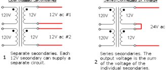
- We connect two windings in series. They are supplied with reduced voltage from the transformer.
- On the third, we will measure the voltage. When switched on, the tester will show some voltage. The value depends on the voltage level coming from the transformer. When turned on oppositely, the tester will show the minimum voltage value.
- We mark both windings accordingly.
- We disassemble the circuit and connect the third winding to any other. We supply voltage from the transformer and take measurements. The diagram is shown in the figure below. However, the circuit supplies a dangerous voltage of 220 volts. In our case, we supply reduced voltage from the transformer.
- By analogy with previous measurements, we determine the beginning and end of the third winding. Labeling.
- Once the wires have been identified and labeled, the motor can be connected in star or delta and connected to the network. In this case, the engine should not make increased noise and heat up. If this happens, you have made a mistake in determining the beginning and end of the windings. If everything is connected correctly, the engine runs smoothly and does not heat up.
A step-down transformer is needed to limit the current in the windings. You can do without it, but to limit the current, a low-power pilot light is turned on in series with the coils.
You should not take risks by supplying 220 volts to the windings without current limitation. In this case, there is a high probability of engine failure. Simply put, you can “burn” the windings.
The beginning and end of the motor windings
Well, let's get started. Before you begin the procedure, you need to prepare. For this you will need:
- multimeter or incandescent lamp (preferably, of course, a multimeter)
- wire markers
- knowledge of safety precautions as you will be working with dangerous voltage
- regular power plug with wire
- something you will use to connect the wires when you start looking for the winding leads
- Well, the material of this article.
As markers, you can use cambrics, paper with erasers, colored electrical tape and regular permanent markers, in general, anything that will allow you to mark the conclusions. You will need six markers on which you will write the beginning and end of the windings.
Expanded triangle method
There is a simpler method for identifying windings in the absence of markings. When connected in a triangle. This is the so-called expanded triangle method. To determine this, you will need the devices used in the first case.
The work is performed in the following sequence:
- Use a multimeter to find the windings.
- Labeled in random order.
- Connect all three coils in series.
- Reduced voltage is supplied.
- Measure the voltage on the windings. If connected correctly, the voltages on the windings should match. Those. U1=U2=U If the value on one of them is different, the ends of this winding should be swapped.
- This is where the check ends. The engine can be mounted on a workplace.
The figure shows a measurement diagram using the triangle method.
If you don't have a multimeter, you can check the voltage using a lamp. The level of luminescence should be the same in all cases. If it is different on one of the windings, then the coil wires are swapped.
Why do you need to consider phase order?
The sequence of alternations plays a significant role in such situations:
- When connected in parallel, a number of devices (transformers, generators and other electrical machines) can be connected in parallel operation to increase the reliability of the system or to provide a greater power reserve. But, in case of incorrect connection, a short circuit will occur due to the connection of opposite phases.
- When connecting a three-phase meter - since its operation is based on the coincidence of phases with the corresponding terminals of the device, then if the connection is not correct, a failure and spontaneous movement may occur in the absence of any load. Because of this, such a connection of the electric meter will lead to the need for the consumer to pay for kilowatts that he did not consume.
- When the engine is turned on, the sequence of phases in the network determines the direction of rotation of the engine for the electric machine. In the absence of correct phasing, the direction of movement of the elements mechanically connected to the rotor will also change. This could result in a disruption of the technological process or a threat to the lives of personnel.
In order to prevent negative consequences from phase imbalance and other mismatches, in practice, they check the alternation and install protection.
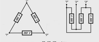
Star connection
This method is used in exceptional cases. After the windings have been found, they are connected in a star and briefly connected to the network. If the wires are connected incorrectly, the engine begins to hum and get hot.
After disconnecting, switch one of the windings and connect it to the network again. There can be no more than three such switches. Remember, turn on the engine briefly, no more than 2 seconds. If left on for longer, the engine will most likely fail.
Protection against alternation violation
To protect electrical equipment from incorrect rotation, a phase control relay is used in practice. This relay is configured to operate the engine or other device when it is connected directly. If due to some malfunction or incorrect connection the alternation is disrupted, the three-phase relay will immediately turn off the device. His work is based on the analysis of three-phase currents and voltages and subsequent monitoring of these parameters.
The connection can be made through current transformers or directly, depending on the model and voltage class of the network. Such protection has found wide application when connecting induction-type meters, electrical machines and other high-precision equipment.
Battery detection
This method requires a tester and a battery. This is the easiest way. The search method using a battery is as follows:
- Using a tester, we find the coils on an asynchronous motor.
- The device is connected to one of them.
- We briefly connect the battery to the terminals of the other one several times. If at the moment the voltage is applied, the tester shows a negative value, this indicates that the windings are switched on oppositely.
- We check all the coils one by one and mark them accordingly.
The measurement diagram is shown in the figure below.
You can check in the same way using the battery. The difference is that a battery is used instead of a battery.
Determination of the working and starting windings of a 220 Volt motor
Often there is a need to determine the working and starting windings in a single-phase motor. This happens due to the loss of the inscription or after repairs.
The motor has four wires. The verification method is as follows:
- Visually inspect the wires. If the wires have different cross-sections, then the starting one will have a smaller cross-section;
- However, it's worth double-checking. We measure the resistance. The winding with a lower value will be working, and the second will be starting.
- We mark conductors.
The measurement diagram is shown in the figure below.
If there are windings with the same resistance, any winding can be used as a working or starting winding. The direction of rotation is changed by swapping the windings.
Single-phase electric motors with three wires are often found. In this case, the tester measures the resistance. We get values, for example, 52 Ohms, 18 Ohms and 34 Ohms. This means that the winding with a lower value (18 Ohms) is the working one, and the second one, 34 Ohms, is the starting one. 52 Ohms is the total resistance of both coils.
The figure below shows a motor diagram with three terminals:
Contents Previous § Next
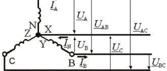
4.4. Pin designation
machine windings
alternating current
The designation of the terminals of the windings of asynchronous and synchronous machines, depending on the purpose of the winding, its placement in the machine (on the stator or on the rotor), the number of ends removed from the machine for connection to the external circuit, and the type of machine is established by GOST 26772-85, which was introduced from January 1 .1987 instead of the corresponding paragraphs (clauses 5.1-5.9) GOST 183-74. GOST 26772-85 provides for two designation systems: for previously developed and modernized machines and for newly developed electrical machines.
For previously developed and modernized machines, the designation system established by GOST 183-74 is retained, according to which the terminals of the windings of synchronous and asynchronous machines are designated by letters of the Russian alphabet (stator windings - with the letter C, rotor - with the letter P, excitation windings of synchronous machines - with the letter I) and numbers. The designation of the terminals of three-phase asynchronous and synchronous machines is given in table. 4.2. The stator winding terminals of single-phase synchronous machines are designated: C/ - phase start, C2 -
end of phase;
excitation windings: I1
- beginning,
I2
- end.
The terminals of the windings of single-phase asynchronous motors are designated: the beginning of the main winding - C1,
end -
C2;
the beginning of the auxiliary winding is
B1,
the end is
B2.
The ends of the windings, connected to each other inside the machine and not brought out to the terminal board of the terminal box or to the slip rings, are not marked. For example, in the stator winding of a three-phase machine, connected in a star inside the machine, only the beginnings of phases C1, C2
and
SZ,
and if there are four terminals, the terminal of the zero point (star point) O. In phase-phase rotors of asynchronous motors, designations are applied only to the winding terminals connected to the slip rings.
The output of the first phase P1
must be connected to the slip ring furthest from the rotor winding;
pin P2
- to the middle one, pin
RZ
- to the ring closest to the winding. The designation of the rings themselves is not necessary.
In drawings of winding circuits, all the beginnings and all ends of the phases are usually designated, and the ends of the phases of the rotor winding are designated similarly to the ends of the phases of the stator winding, i.e. P4, P5, P6.
The beginnings and ends of the phases of the sectioned windings of the machine are indicated by the same letters and numbers as simple windings, but with the addition of numbers before the capital letters that identify each of the windings. So, with two windings in a machine, the terminals of the first of them are designated 1 Cl, 1C2, 1СЗ -
the beginnings of the phases and
1С4, 1С5, 1С6
- the ends of the phases; conclusions of the second winding - corresponding
Table 4.2. Designations of three-phase asynchronous and synchronous winding terminals
machines (according to GOST 183-74)
Winding name
| Connection diagram | Number of pins | Pin name | Letter designation of terminals | ||
| Start | End | ||||
| Stator winding of asynchronous and synchronous three-phase machines | Open circuit | 6 | First phase Second phase Third phase | C1 C2 NW | C4 C5 C6 |
| Star | 3 or 4 | First phase Second phase Third phase Zero point | C1 C2 NW 0 | III | |
| Triangle | 3 | First clamp Second clamp Third clamp | C1 C2 NW | — | |
| Winding of a phase rotor of an asynchronous machine | Star or triangle | 3 | First phase Second phase Third phase | P1 P2 RZ | — |
| Star | 4 | First phase Second phase Third phase Zero point | P1 P2 RZ 0 | 1 III | |
| Excitation winding (inductor) of a synchronous machine | 2 | I1 | AND 2 | ||
| Stator winding of a single-phase machine | — | 2 | — | C1 | C2 |
| Stator winding of a single-phase (two-phase) asynchronous motor | — | 4 | Main winding Auxiliary winding | C1 B1 | C2 B2 |
| 3 | Main winding Auxiliary winding Common point | C1 B1 0 | — | ||
specifically 2S1, 2S2, 2SZ
and
2S4, 2S5, 2S6.
In multi-speed machines, the terminals of individual and pole-switching windings are designated in the same way as the terminals of simple windings, but with additional numbers in front of the capital letters indicating the number of winding poles when connected to the network of these terminals. For example, the terminals of a pole-switching winding of a machine at 2p =
4 and 6 are designated
4С1, 4С2, 4СЗ
and
6С1, 6С2, 6СЗ, respectively.
For winding terminals, newly developed
for machines being built, GOST 26772-85 establishes designations corresponding to ST SEV 3170-81 and IEC Publications. 34-8 (Table 4.3). The conclusions are designated by the letters of the Latin alphabet U, V, W,
Moreover, the beginnings and ends of each phase are additionally marked with numbers after the letters: the beginning is with the number /, the end is with the number 2, for example
Ul, U2, VI, V2;
Wl, W2, and intermediate terminals - letters and subsequent numbers 3, 4, etc. If there are windings with the same letter designations, additional
Table 4.3. Designation of terminals of three-phase asynchronous and synchronous machines
(according to GOST 26772-85)
| Designation | ||||
| Name. Scheme | Number | Phase name | conclusions | |
| winding connections | conclusions | and output | ||
| Start | End | |||
| Stator winding. Open circuit | 6 | First phase | U1 | U2 |
| ma | Second phase | VI | V2 | |
| Third phase | W1 | W2 | ||
| Stator winding. Star | 3 or 4 | First phase | 1 | J |
| Second phase | V | |||
| Third phase | W | |||
| Star point | N | |||
| Stator winding. Triangle | 3 | First conclusion | And | |
| Second conclusion | \ | |||
| Third conclusion | W | |||
| Sectional winding | 12 | First phase | VI | U2 |
| Torah | Conclusions from the first phase | from | U4 | |
| Second phase | VI | V2 | ||
| Conclusions from the second phase | V3 | V4 | ||
| Third phase | (VI | W2 | ||
| Conclusions from the third phase | W3 | W4 | ||
| Split stator windings, | __ | First phase | U1 | U2 |
| intended for consistent | U5 | U6 | ||
| telny or parallel | Second phase | VI | V2 | |
| inclusion | V5 | V6 | ||
| Third phase | W1 | W2 | ||
| W5 | W6 | |||
| Separate stator windings, | First phase | 1U1 | 1U2 | |
| intended for consistent | 2U1 | 2U2 | ||
| telny or parallel | Second phase | IV 1 | 1V2 | |
| inclusion | 2 VI | 2V2 | ||
| Third phase | 1W1 | 1W2 | ||
| 2W1 | 2W2 | |||
| Multi-speed stator windings | 6 | Conclusions of the first phase | 1U-2N | 2U |
| ny asynchronous motors. | Conclusions of the second phase | 1V-2N | 2V | |
| Closed circuit | Conclusions of the third phase | 1W-2N | 2W | |
| 9 | Conclusions of the first phase | 1U-3N | 2U; 3U | |
| Conclusions of the second phase | 1V-3N | 2V; 3V | ||
| Conclusions of the third phase | 1W-3N | 2W; 3W | ||
| 12 | Conclusions of the first phase | 1U-2N | 2U | |
| 3U-4N | 4U | |||
| Conclusions of the second phase | 1V-2N | 2V | ||
| 3V-4N | 4V | |||
| Conclusions of the third phase | 1W-2N | 2W | ||
| 3W-4N | 4W | |||
| Asynchronous phase rotor winding | First phase | K1 | K2 | |
| chronic engine, open | 6 | Second phase | L1 | L2 |
| scheme | Third phase | Ml | M2 | |
Continuation of the table. 4.3
| Name. Winding diagram/connections | Number of pins | Name of phase and output | Pin designation | |
| Start | End | |||
| Winding of the phase rotor of an asynchronous motor. Star | 3 or 4 | First phase Second phase Third phase Star point | To L M Q | |
| Winding of the phase rotor of an asynchronous motor. Triangle | 3 | First output Second output Third output | To L M | |
| Excitation winding of synchronous machines | — | — | F1 | F2 |
extra numbers before letters, for example 1U1, 2U1
etc.
In the designation of separate motor windings switched to a different number of poles, the smaller number in front of the terminal letter designation corresponds to a lower rotation speed, and the larger number corresponds to a higher rotation speed.
Double designation, for example IV - 2N, IV - 3N
etc., is used for terminals that are connected to the network at one speed of multi-speed motors, and short-circuited to each other at another. If there is no place on the terminal board for applying a double designation, it is allowed not to indicate the second half of the double designation, but in this case a winding connection diagram must be attached to the machine.
In the drawings of winding circuits with six output ends, when connecting the phases in a triangle, it is allowed to use double designations (U1W2, V1U2, W1V2) in the free field of the drawing,
and when connecting the phases into a star - the designations of the beginnings of the phases
(U1, VI, W1)
and the triple designation of the star point
(V2, V2, W2).
When using designations for the internal connection terminals of the windings, they should be indicated in parentheses, for example, the point of connection of the windings of a phase-wound rotor of an asynchronous motor in a star is designated
(Q).
The designations of the winding terminals of two-phase AC machines are formed from the designations of three-phase machines (see Table 4.3) without the letters W
and
M.
The terminals of single-phase synchronous and asynchronous machines are designated in accordance with table. 4.4.
Temperature sensor leads
Table 4.4. Designations of winding terminals
single-phase asynchronous and synchronous machines
(according to GOST 26772-85)
| Designations | ||
| Winding name | conclusions | |
| or conclusions | ||
| Start | End | |
| Stator windings: | ||
| main winding | VI | U2 |
| auxiliary | Z1 | Z2 |
| winding | ||
| Field winding | F1 | F2 |
| synchronous machines | ||
| Winding terminals for re- | R1 | R2 |
| le rotation speed | ||
| Additional findings | XI | X2 |
| (capacitor, disconnect- | ||
| nitel, etc.) | ||
shields of newly developed machines that respond only to temperature should be designated: 77 - beginning, 72 - end, and sensors that respond to temperature and current: beginning - P1,
end -
P2.
All terminal designations are applied directly to the ends of the windings (on cable lugs, on bus ends or on special crimps tightly fixed to the wires). Attaching tags with designations to the ends of the windings is not allowed.
For all machines developed previously, modernized and newly developed with a body diameter of no more than 40 mm, in which the letter designation of the output ends is difficult due to lack of space, it is allowed to use color coded designations of the outputs - wires with multi-colored insulation, paint, etc. Color designations
The values of the output ends of the windings are given in Table. 4.5 and 4.6.
The terminals of the stator windings of two-phase asynchronous motors can have alphanumeric, digital or color codes (Table 4.7).
Designations of the terminals of stepper motors and information machines (tachogenerators, synchronizers, induction sensors
Table 4.5. Color designation
stator winding terminals of three-phase machines
alternating current
| Winding connection diagram | Number CONCLUSIONS | Name of phase or output | Pin color code | |
| Start | End | |||
| Open circuit | 6 | First phase Second phase Third phase | Yellow Green Red | Yellow with black Green with black Red with black |
| Star | 3 or 4 | First phase Second phase Third phase Zero point | Yellow Green Red Black | 1111 |
| Triangle | 3 | First output Second output Third output | Yellow Green Red | — |
Table 4.6. Color designation of stator winding terminals of single-phase motors
| Number of pins | Name of winding or terminals | Pin color code | |
| Start | End | ||
| 4 | Main winding Auxiliary winding | Red Blue | Red with black Blue with black |
| 3 | Main winding Auxiliary winding Common point | Red Blue Black | — |
angle, etc.) are given in the second volume of the Handbook.
The relative position along the slots of the stator or rotor of the beginnings of the distributed phases
Table 4.7. Designations of the winding terminals of two-phase asynchronous motors (according to GOST 183-74)
| Winding name | Alphanumeric code | Digital code | Color code |
| Excitement | Bl, B2 | 1, 2 | Red Blue |
| Management | U1, U2 UZ, U4 | 3, 4 5, 6 | White, black White, black |
windings must obey the following rule: the electrical angle between the beginnings of the winding phases must be equal to the angle between the supply voltage vectors or an integer number of times greater than it. Thus, the electrical angle between the beginnings of the phases of a three-phase winding should be equal to 120 °k,
where
k
is any integer not a multiple of 3. The electrical angle between the beginnings of the phases of a two-phase winding must be equal to 90
“k,
where
k is
any integer not a multiple of 2.
In stators, they try to arrange the winding terminals as compactly as possible, so in most cases they take k = 1.
In this case, in three-phase windings the beginnings of the phases are located at 120° intervals, i.e. through
2q
tooth divisions, and in two-phase windings at 90°, i.e. through
q
tooth divisions.
The beginnings of the phases of the windings of the phase rotors of asynchronous motors tend to be located symmetrically around the circumference of the rotor in order to avoid an imbalance that will appear when the beginnings of the phases and jumpers in the phases are unevenly located around the circumference. In three-phase machines, both conditions are compatible when k = p.
In machines with
p
divisible by 3, it is not possible to achieve complete geometric symmetry in the location of the output ends of the rotor winding.
Contents Previous § Next
DC motors
DC motors usually have two wires. Therefore, when voltage is applied, it begins to rotate in a certain direction. If the rotation does not match, in this case the polarity is changed.
You can connect a stepper motor in a similar way. For example, there are four pins. The coils of such an engine have the same resistance, and the wires, as a rule, are colored.
We connect it to the driver in random order and see in which direction the rotation occurs. If it is necessary to change the direction of rotation, the wires are swapped.
For example, connected - white, blue, red, black. To change the direction, connect - black, red, blue, white.
So we looked at how to determine the beginning and end of the electric motor windings. If you have any questions about this topic, ask them in the comments below the article!