20/03/19
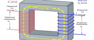
A transformer is needed to increase or decrease the AC current values. Its main parts are input and output (sometimes 1) coils located on a magnetic core. The operation of the device consists of a 2-way change in the magnetic field induced by alternating current. When using DC current, it must first be converted. Alternating voltage is supplied from outside to the primary winding. An alternating voltage is generated on the secondary coils following it. Transformers come in different types and are made from different materials. The shape is determined by the ease of placement of the transducer in the device body. Rated power depends on the type and material of the core. Depending on the characteristics of the core and differences in the number of turns, the transmission coefficient varies.
Possible faults
Common transformer failures include:
- burnout of the cable in the reel;
- insulation damage causing turn-to-turn short circuit or electrical contact between the coil and the housing;
- core defect;
- natural wear of winding terminals or contacts.
A visual inspection of the transformer can reveal damaged or missing insulation, faulty terminals and bolts, swelling or leaking. Also, during inspection, you need to pay attention to the presence of blackness, charring of the paper, and a burning smell. If there is no visible damage, the functionality of the device will be checked using measuring instruments.
Transformer types
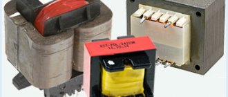
There are different types of step-down TN. The usual and most common is single-phase for a 220 V network. There are also two- and three-phase for 380 V. The most standard composition: two windings and a laminated core made of electrical steel.
Certain types of VTs are equipped with 1 winding - these are autotransformers, they can also step down / step up. In this case, there are at least 3 conclusions. A 220 V connection is made to one pair of contacts, and the output value is taken from one of the input pairs of terminals and from the other that remains free. But autotransformers cannot be used in wet rooms, since the coils in them are connected, that is, the consumer is also connected to 220 V.
Why is comprehensive diagnostics of transformers needed?
To assess the technical condition of electrical equipment, engineering specialists perform comprehensive diagnostics of transformers. With its help, you can identify potential threats and defects that could lead to an accident at a power facility. Based on the data obtained, a concept is being developed to extend the service life of equipment by replacing worn-out working units. A comprehensive examination of transformers is performed in the following cases:
- there is an urgent need for a major overhaul of electrical equipment;
- it is necessary to draw up an expert technical report in case of emergency shutdown of equipment;
- for technical substantiation of identified defects during various types of inspections;
- to determine the conditions and standards for the operation of equipment in accordance with State Industry Standard 11677.
Timely inspection of power transformers reduces the risk of downtime due to emergency stops and increases the reliability of operation of the entire energy facility.
Methods for diagnosing power transformers
The list of diagnostic procedures includes the following work:
- checking the condition of the winding and its insulators;
- checking the characteristics of transformer oil;
- switch diagnostics;
- checking the ventilation system.
Inspection and testing of power voltage transformers begins with examining the condition of the winding.
| Power and voltage class of the high voltage winding (HV) | Temperature in C | |||||
| 10 | 20. | 30 | 40 | 50 | |||
| Up to 35 kV inclusive with a power of less than 10 MVA | D S/S ratio at the end of the audit in % | 13 | 20 | 30 | 45 | 75 |
| The difference between the value of A C/C at the end and beginning of the audit in % | 4 | 6 | 9 | 13,5 | 22 | |
| Transformer power and voltage class of HV winding | in % AT winding temperature in e C | ||||||
| 10 | 20 | 30 | 40 | 50 | 60 | | 70 | |
| Up to 35 kV inclusive with a power of less than 2,500 kVA | 1,5 | 2 | 2,6 | 3,4 | 4,6 | 6 | 8 |
| Up to 35 kV inclusive with a power of less than 10,000 kVA | 1,2 | 1,5 | 2 | 2,6 | 3,4 | 4,5 | 6 |
Diagnostic procedures can detect radiological interference as well as the presence of moisture in transformer oil. After turning off the equipment, engineering experts measure current resistance, insulation resistance and determine loss coefficients. Checking the secondary circuits of voltage transformers is carried out according to the manufacturer's instructions.
| Transformer insulation type | Test voltage in V at rated winding voltage in kV | ||||||
| up to 0.525 | 3 | 6 | 10 | 15 | 20 | 30 | |
| Normal. | 5 | 18 | 25 | 35 | 45 | 55 | 85 |
| Lightweight. | 3 | 10 | 16 | 24 | 37 | ||
The next step is to examine the performance characteristics of transformer oil: color, viscosity, tension, density, insulation resistance, the presence of impurities (moisture, gases) in it. During diagnostics, insulation indicators and grounding quality are measured. The technicians also pay attention to checking the stability of the contact in the switch, measuring its temperature and the number of kV of the electric motor. The parameters that are studied in the ventilation system are the following:
- air flow quality;
- vibrations in bearings;
- indicators of current in the winding;
- cleanliness of surfaces.
To determine the degree of wear of the insulating material, methods such as identifying the degree of concentration of furfural derivatives, carbon oxide and carbon dioxide, and measuring the degree of polymerization are used. Based on the data, the maximum permissible time for further operation of the insulating material is determined. The frequency of inspections of transformers depends on their purposes: the current one is carried out at least once a month. A comprehensive check with measuring instruments for the purpose of subsequent major repairs of technical equipment is carried out every 3-4 years.
How to check the operation of a transformer with a multimeter
You can diagnose the serviceability of the converter with a multimeter. The diagnostic sequence is as follows: 1. Determination of windings. The converter usually has markings indicating the numbers and type of pins. Using the designations, you can obtain additional information from reference books. For converters installed in electronic devices, you can use device diagrams and detailed specifications. 2. Using a tester. It allows you to identify 2 typical problems - a broken winding and a short to a nearby winding or housing. 3. If there is a suspicion of a winding break, ring all of them one by one with an ohmmeter. The break is confirmed by a resistance equal to infinity. For measurements, it is better to use an analog ohmmeter, since a digital one can distort the readings due to significant induction values. This is most relevant for coils with many turns. 4. Monitoring a short circuit to the housing - 1 probe contacts the winding terminal, and the 2nd probe rings the terminals of the remaining windings and the housing. The contact area on the body is cleared of paintwork in advance.
Varieties
Depending on the design features, the following types of pulse transformers are distinguished:
- rod;
- armored;
- toroidal, with wire wound on an insulated core, which does not require the use of coils;
- armored rods.
Types of magnetic cores The cross-section of the core in most devices is in the shape of a circle or rectangle, by analogy with power devices.
Also read: KTPN - outdoor complete transformer substation
The main characteristics of the devices are marked on the case, so from the symbol you can glean information about the main parameters of the equipment.
Detection of inter-turn short circuit
To identify such a defect in a pulse transformer, a multimeter is not enough. At a minimum, you will also need good eyesight and attentiveness. To insulate the wire, only its varnish coating is used. In the event of an insulation breakdown, resistance remains between adjacent turns, and the contact area heats up. Therefore, you need to make sure there are no leaks, swelling, burning smell, blackness, or burning. After determining the type of converter, you can see the resistance value of its coils in the reference book. After this, you should use a tester in the megohmmeter functionality to measure the insulation resistance - between pairs of windings and separately between each of them and the housing. Measurements are carried out at the voltage indicated in the technical documentation for the converter. The measured values are compared with the reference values, and if there is a discrepancy of 50% or higher, a winding fault is diagnosed.
What functions does a transformer perform?
Transformers are widely used in battery chargers.
The main function of transformers is to reduce or increase the voltage of the current supplied to them. These devices are widely used in high-voltage networks that deliver electricity from the point of generation to the end consumer.
In a modern household it is difficult to do without a current transformer. These devices are used in all types of equipment, from refrigerators to computers.
Until recently, the size and weight of household appliances were often determined precisely by the parameters of the transformer, because the basic rule was that the higher the power of the current converter, the larger and heavier it is. To see this, just compare the two types of chargers. Transformers from an old mobile phone and a modern smartphone or tablet. In the first case, we will have a small but weighty charging device, which gets noticeably hot and often breaks down. Pulse transformers are characterized by silent operation, compactness and high reliability. The principle of their operation is that the alternating voltage is first supplied to the rectifier and converted into high-frequency pulses, which are fed to a small transformer.
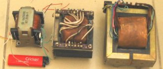
When repairing equipment at home, there is often a need to independently wind the transformer coil. For this purpose, prefabricated cores are used, which consist of individual plates. The parts are connected to each other by means of a lock, forming a rigid structure. Winding with wire is done using a homemade device that works on the principle of a rotator.
When creating such a transformer, you should remember: the tighter and more neatly the wire is wound, the fewer problems will arise with the operation of such a device.
The turns are separated from each other by a single layer of paper coated with glue, and the primary winding is separated from the secondary by a gap of 4-5 layers of paper. Such insulation will provide protection against breakdowns and short circuits. A correctly assembled transformer guarantees stable operation of the equipment, the absence of annoying hum and overheating.
Diagnostics of household step-down transformers
Such elements are contained in power supplies that reduce the voltage at the 220 V input to a value of 5–30 V at the output. Before checking the operation of a step-down transformer, you must first make sure that its primary winding is in good condition. If a burning smell, smoke or crackling occurs, measurements must be stopped. If the described defects are not identified, measurements are performed on secondary coils. During the measurement process, it is permissible to touch them only with the probes of the tester. Measurement data is compared with control data. If the discrepancy is 20% or more, a winding fault is confirmed. But it will be possible to test such a block only if there is a 100% identical working block, which is necessary to assemble the control data. When working with a resistance of about 10 Ohms, the results may be distorted (typical of some testers).
Questions about the transformer design
How to properly install the mass switch on a car
-Why is the gap between the coils kept to a minimum? This is done for better contact of magnetic fields. If the gap is large, then the efficiency of the transformer will be low.
-Is it possible to make a transformer without a core with the same power as one with a core? Yes, but then you will have to increase the number of turns to increase the magnetic flux. For example, with a core, the windings can have several thousand turns. And without a core, you will have to increase the magnetic flux due to turns. And the number of turns will be several tens of thousands. This not only increases the size of the coils, but also reduces their efficiency and increases the chances of overheating.
-Is it possible to connect a step-down transformer as a step-up transformer? If you have a transformer that lowers the mains voltage from 220 V to 12 V, then it can be connected as a step-up one. That is, you can apply an alternating voltage of 12 V to the secondary winding and get an increased voltage of 220 V on the primary.
-What will happen if mains voltage is applied to the secondary winding of the step-down transformer? Then the winding will burn out. Its resistance, number of turns and wire cross-section are not designed for such voltages.
-Is it possible to make a transformer yourself with your own hands at home? Yes, this is quite possible. And many radio amateurs and electronics engineers do this. And some also earn money. selling finished products. But it is worth remembering that this is long, complex and not easy work. We need quality materials. This includes transformer iron, enameled copper wires of various sections, and insulating materials.
All materials must be of high quality. If the copper wire is poorly insulated, then an interturn short circuit is possible, which will inevitably lead to overheating. First you need to calculate all the parameters of the future transformer. This can be done using various programs that are available online.
Next, there are long hours of assembly. Especially if you decide to wind a toroidal transformer. You need to wind the turns tightly and evenly, write down every ten so as not to get confused and not change the characteristics of the future converter or power supply.
-What happens if you turn on a transformer without a core? Since the transformer was initially designed with a core, it will not be able to completely convert the voltage. That is, there will be something on the secondary, but obviously not the same parameters. And if you connect a load to windings without a core, they will quickly heat up and burn out.
Transformer faults
The main malfunctions of transformers include:
- Corrosion and rust on the core;
- Overheating and insulation failure;
- Interturn short circuit;
- Deformation of the housing, windings and core
- Water getting into the winding.
How to check for integrity
The transformer can be checked with a conventional multimeter. Set the device to resistance measurement mode and check the windings.
They shouldn't be on edge, ever. If there are no breaks anywhere, then you can find the primary and secondary windings by measuring resistance. The primary winding of a step-down transformer will have a higher resistance than the secondary winding. This is all due to the number of turns. The more turns and the smaller the diameter of the wire, the greater the winding resistance.
You can also find a passport for your transformer. It indicates the resistance of the windings and their parameters, which will need to be checked with a multimeter.
Safely test transformer operation
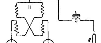
If you decide to wind your transformer or test the old one, then be sure to connect the light bulb to the open circuit (in series!). If something wrong happens, the light bulb will light up and take over the current and be able to save the faulty transformer.
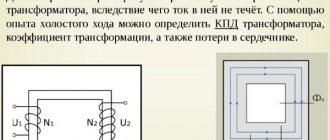
Determination of no-load current
If the previous test work does not reveal a malfunction, it is recommended to perform diagnostics on the idle current. Often it is 0.1-0.15 of the nominal value. To perform diagnostics, the measuring device is used in ammeter mode. The multimeter is connected to the device being diagnosed with a short circuit. This condition is important because when current is supplied to the coil, its value increases hundreds of times compared to the nominal value. After opening the tester terminals, the display shows the current value without load, i.e. current XX. Its values are measured identically on the secondary coils. A rheostat is usually used to determine voltage. An alternative to it can be a tungsten spiral or a set of lamps. To increase the load, the number of spiral turns is reduced or the number of bulbs is increased.
Formula for calculating transformer turns
P=U2*I2 (transformer power)
Sheart(cm2)= √ P(va) N=50/S
I1(a)=P/220 (primary winding current)
W1=220*N (number of turns of the primary winding)
W2=U*N (number of turns of the secondary winding)
D1=0.02*√i1(ma) D2=0.02*√i2(ma) K=Swindow/(W1*s1+W2*s2)
50/S is an empirical formula where S is the area of the transformer core in cm2 (width x thickness), and is believed to be valid up to a power of about 1kW. Having measured the area of the core, we estimate how many turns need to be wound at 10 volts; if this is not very difficult, without disassembling the transformer we wind the control winding through the free space (slot).
We connect the laboratory autotransformer to the primary winding and apply voltage to it, turn on the control ammeter in series, gradually increase the voltage with the LATR until the no-load current begins to appear.
If you plan to wind a transformer with a fairly “hard” characteristic, for example, it could be a transmitter power amplifier in SSB, telegraph mode, where rather sharp load current surges occur at high voltage (2500 -3000 V), for example, then the no-load current The transformer is set to about 10% of the maximum current, at the maximum load of the transformer. Having measured the resulting voltage of the wound secondary control winding, we calculate the number of turns per volt.
Monitoring the circuit under load - direct method
This method is used to check the operating parameters of the converter. Its essence is to determine the currents in the windings under load. A load is connected to the secondary winding such that the currents flowing in the windings are at least 20% of the rated values. If there are several secondary windings, those not connected to the load must be short-circuited. This is for safety reasons to avoid high voltage in the open secondary coil. The obtained values are divided among themselves, and the transformation coefficient is determined. If it corresponds to the rated value, the serviceability of the device is confirmed; if it does not, the defect must be determined.
Ready-made solutions - nuclear fuel technology boxes
YaTP is a step-down transformer immediately ready for connection, a module. No need to deal with pins, inputs, windings. The product has appropriately marked sockets for the required load, 36V or otherwise. It is enough to plug its cable into a 220 V network and connect it to the socket on the consumer’s body.
Nuclear fuel transformers can produce any low voltage - 24, 36, 42 V. They are often used for temporary repair work. There are models that allow you to adjust the output voltage.
