A contactor is an electromagnetic device designed for switching, that is, turning on and off electrical equipment. It is a two-position mechanism that is used for frequent switching. The main elements of its design are:
- Power contact group, which can be two or three-pole depending on the voltage required for the operation of the actuator.
- Arc suppression chambers, which are aimed at reducing the arc that occurs when an electric current breaks;
- Electromagnetic drive. It is designed to move the moving part of the power contact. Depending on the design, it can be designed for different voltages, both direct and alternating current. Made from a U-shaped or W-shaped core;
- A system of block contacts required for signaling and controlling the operational circuits of the contactor. Using them, you can connect a sound or light alarm indicating the position of the contactor, as well as for the self-retaining circuit.
A distinctive feature of the design of an electromagnet operating with alternating current is the presence of a short-circuited coil, which prevents its iron from humming during operation. If the electromagnet operates on direct current, then between its disconnected parts there must be a non-metallic gasket that prevents the core from sticking. A contactor differs from a magnetic starter or relay, only in working with a more powerful load; the dimensions of the device itself depend on its size. It is very important to choose the right contactor corresponding to the current that it will switch.
Modern devices of the KMI series have good reliability indicators and are intended for general industrial use. Due to their design, they have an easy method of fastening and small dimensions.
What is a contactor?
In a general sense, this is a remote switch/switch in the electrical network.
Unlike many other switching devices, the contactor has a large safety margin, breaking the electrical network in several places at once, allowing frequent switching on and off of significant loads of powerful electric motors, reactive power compensation systems and other electrical consumers. The operating principle of a contactor is to move an electromechanical coil or relay. When control voltage is applied, the magnetic armature is attracted to the core, closing the power electrical circuit. Since the contactor can have up to 5 groups of contacts, switching occurs in accordance with preliminary settings, or under the guidance of a microprocessor. Each contact can be switched to a normally closed or normally open state.
Modern models have the ability to connect additional external equipment: additional contact attachments, time relays, thermal relays, blocking devices. Thanks to this, the contactor differs from any other switching equipment in its significantly greater versatility and flexibility in setting its operation. For example, a contactor with a thermal relay performs the functions of a magnetic starter, and when setting a delay, it acts as a time relay.
Design and principle of operation
A standard contactor design includes several basic parts. The device consists of a housing (1), a control coil output terminal (2), a power contact terminal (3), a fixed magnetic core (4), a moving part - a core (5), a control coil (6), a short-circuited magnetic circuit ring (7), fixed and moving contacts (8 and 9), on-off indicator lever (10).
The coil is the main element that creates the magnetic current. If it is also used as a throttle, then with its help a driving force is generated that ensures the operation of the devices. The tension of the contacts is fixed using a contact spring. During docking, the moving and fixed contacts are connected to each other. They are constantly in motion and perform certain actions. Fixed contacts are fixed to the body, and movable contacts are connected to the core.
The contactor works as follows:
- After applying voltage to the control coil, the armature is attracted to the core. As a result, the contact group closes or opens, in accordance with the initial position of a particular contact.
- After turning off the power, all actions occur in the reverse order. The electric arc that occurs at the moment of opening is extinguished using an arc extinguishing system.
- After the voltage supply is stopped, the electromagnetic field disappears and ceases to hold the armature or core.
- The return spring moves the contacts to their original position, completely opening the circuit. Thus, the modular contactor performs its main work during periods of supply and shutdown of voltage.
Why do you need a contactor?
Just like the subtypes, the original contactor is needed to control the electrical circuit. But it has several operating features:
the ability to fully automate the switching on and off of the circuit;
high speed of operation, allowing the circuit to be closed and opened up to several thousand times per hour.
Thanks to these features, contactors are used in areas where electrical circuits need to be activated regularly and frequently. Doing this manually is not only inconvenient, but even ineffective. So it is better to entrust the work to an automated system.
Where are contactors used?
What are contactors used for? The areas of application of these devices are varied:
- utilities: management of lighting, elevators, ventilation and heat and water supply systems;
- in industry and construction, contactors are found in almost all electrical devices;
- for electric transport: in trams and trolleybuses, these devices are responsible for the operation of the traction motor;
- in domestic conditions, with the help of contactors, they automate the operation of intra-house electrical networks.
Depending on the functions, there are also highly specialized contactors designed to work, for example, only with motors or construction electrical equipment. Before you buy a device of this type, you need to decide exactly where and under what conditions it will work.
Types of contactors and applications
Such devices differ depending on the type of connection break into dual models, which are characterized by increased operational safety, and single analogues, used for hydroelectric power plants, railway cars, and induction furnaces. Based on the type of control, switching devices are divided into models with manual or remote control.
Depending on the type of installation, frameless and framed contactors are distinguished. Depending on the type of electric current, there are DC and AC voltage models. These mechanisms are also classified according to the number of poles, rated current and voltage, as well as operating frequency.
For anyone who does not understand why a contactor is installed, it is recommended to imagine how difficult it would be for people to get along without such devices. Thanks to such inventions, the danger of short circuits and fires in production is minimal. Since these two-position devices control the flow of current in certain circuits, their scope of application is quite wide:
- automation of lighting systems;
- household spheres and public transport (trams, trolleybuses, electric locomotives, elevators);
- industrial production;
- automotive systems;
- organizing the operation of various systems and equipment (heated floors, fans, heating pumps, compressors, etc.);
- prompt load switching at different facilities.
Conventional modular contactor
Using a conventional modular contactor, remote control of electrical consumers is organized via radio or Wi-Fi communication channel. The smart home system is capable of taking into account many specified parameters.
For example, through a “smart” thermometer it is possible to organize control of electric heaters without human intervention. When the air temperature in the room decreases, the thermometer will give the contactor a command to turn on the outlet to which the heater is connected. When the set temperature is reached, the outlet will automatically turn off power. In this case, the contactor will be installed in the electrical panel, that is, externally such a system is no different from a conventional one.
If necessary, a gas boiler is connected via a remote contactor. This will save money, because a gas boiler with GSM control costs much more than a conventional one. If necessary, the contactor can be turned on from any geographical point, the gas boiler will start working, and the house will warm up well by the time the owner arrives.
We recommend reading: DIY DC voltage multiplier
The modular contactor has a number of advantages over other models:
- Silence. Switching occurs through a small relay that produces a quiet click. More expensive models are equipped with solid-state relays that do not make sounds at all.
- Easy installation. Most contactors can be mounted on a DIN rail, which is equipped with all electrical panels.
- High versatility. Contactors are available for sale with any rated current, voltage and number of contacts. Some of them have a diode bridge, which allows you to connect DC consumers to the contactor.
- High reliability. Contactors have a large safety margin, and many models are equipped with noise suppression systems, protecting expensive equipment connected to it.
Electromagnetic contactor
A simple electromagnetic contactor differs from a modular one in the way of switching, namely, it has an electromagnetic coil. To organize power supply for consumers, block contacts are used. When the contactor is turned on, all contacts operate simultaneously.
The use of such contactors is advisable for switching powerful or three-phase electrical consumers: water pumps, a lathe in a workshop, and so on.
An electromagnetic contactor can also be installed in a home's electrical panel and controlled remotely or via signals from various relays.
Most often, such contactors can be found in a water supply system with a hydraulic accumulator. The block contacts are set to a normally closed state; when the contactor is turned on, the well pump supplies water to the hydraulic accumulator. When the required pressure inside the accumulator is reached, the pressure switch sends a command to turn off the contactor. The process is repeated as water is consumed by the residents of the house.
Depending on the power, when the consumer is disconnected, sparking of the contacts may occur, which has a detrimental effect on their service life. Electromagnetic contactors are equipped with arc-extinguishing chambers, making it possible to disconnect consumers under load without the risk of high-temperature electric arc formation.
Where and why is it used?
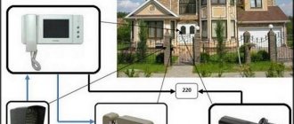
Most often, a modular contactor is used to control and switch a heating pump and other various devices (for example, in ventilation systems). They have become popular and in demand when assembling panels in apartments and various automation systems. For example, control of light, well pump, automatic reserve switching circuit, and so on. Why? Because the contactor fits perfectly with other modular devices, without disturbing the ergonomics of the switchboard. You can verify this by looking at the visual example in the photo:
It is worth remembering that the mains voltage should be no more than 380 Volts at a frequency of 50 Hz. But despite this, the contactor can operate at high powers. There are several other advantages of this device. Such as the almost complete absence of noise and vibration, which has a rather positive effect when used not only in a home panel, but also in public places (hospital, apartment, schools, institutes, etc.), since other switching devices are too susceptible to strong vibration.
By the way, size matters. After all, the small size of the modular contactor allows it to be installed on a DIN rail. The design includes arc-extinguishing chambers to extinguish the arc that occurs when the current load changes. In addition, there are single-phase and two-phase contactors, which allows you to connect to any network.
You can learn more about modular contactors by watching this video:
Pros of using a contactor
Using a contactor offers several advantages:
- You can turn on the lighting remotely, including via the Internet or Wi-Fi.
- Can switch a higher level of currents compared to a conventional wall switch.
- The voltage of the contactor coil may differ from the supply voltage of the lamps both in the type of current and in level. Therefore, if necessary, it is possible to decouple power and control circuits, and thereby increase safety during operation.
- Contactors can be used to implement any lighting switching scenarios. For example, use switching on from a controller or sensor, and when divided into groups, sequential switching on of groups to reduce the inrush current or partial switching on to save energy.
- You can turn off all lighting groups at the same time by pressing one button.
If we talked about the advantages of contactors, let’s also talk about the disadvantages. The main disadvantage of this solution is that due to the complexity of the scheme, its price increases. However, in some cases, the use of contactors is the only way out. And the price of a contactor and its control circuits is often negligible compared to the price of lamps and the cost of their installation.
Basic faults
Possible breakdowns of contactors include failure of the magnetic control coil, as well as burning and failure of the switching contacts themselves. In the first case, the only possible way out is to replace the coil with a new, working sample. If the contacts burn, you can try to restore them by lightly cleaning the damaged areas, first with a file and then with fine sandpaper. However, such a “cosmetic” operation is not a solution. Sooner or later, the user will have to replace the burnt contacts with new (backup) or samples taken from another device.
How to choose a contactor
The larger the device, the more powerful the load it can handle. It is important to pay attention to the fact that the coil voltage is equal to the control voltage, and the contacts can withstand the load when connecting all consumers. There are 3 classes of switching wear resistance of such devices (A, B and C). It is better to choose a product with a small supply of this parameter.
Before selecting a contactor, it is important to have an understanding of the operating conditions. Based on this, the optimal degree of protection is selected. For example, if the equipment will be located in an electrical cabinet, then it is enough to purchase a model with a degree of protection IP20. For dusty rooms or objects with high humidity, you should choose more protected enclosures (IP45 or 65). A protection module equipped with a thermal relay can save you from overloads.
Characteristics of contactors
To choose the right device for your needs, you need to know what characteristics this type of device has and how they differ. Typically, electromagnetic contactors have the following important characteristics:
- Limit and rated voltage;
- Correlation of work with various circuit breakers (protecting against short circuits);
- Parameters and types of acceleration regulators of automatic circuit breakers;
- Characteristics and type of resistances;
- Type and nature of relays and releases and other elements in its composition.
Review of modular contactor manufacturers
The modern market is replete with many different switching devices, including electromagnetic ones. Modular contactors are especially popular, and therefore are represented by a variety of models from both domestic and foreign manufacturers. All of them are of high quality and reliability. However, prices for products vary markedly.
For comparison, the table summarizes some products from different companies:
| Brand name | A country | product name | Number of poles | U nom., Volt | price, rub. |
| Schneider Electric | France | Acti 9 ICT 63A 4NO | 4 | 400 | 10780 |
| IEK | China | KM63-40 4R 63A | // | // | 2000 |
| ABB | Switzerland | ESB-63-40 (63A) | // | // | 5600 |
| TDM | Russia | KM63/4 4AR 63A | // | // | 1600 |
| EKF | Russia | KM 3R 63A | 3 | // | 2500 |
The technical parameters of the products indicated in the table are similar, however, the prices for each are different. The brand name has a lot to do with it, but the choice is always up to the user. Many believe that famous manufacturers monitor product quality better and, accordingly, deserve more trust. The main thing is not to purchase goods of dubious origin.
What is the difference between a contactor and a magnetic starter
Very often contactors are confused with magnetic starters and this is justified, since in essence they are the same thing. These types of devices are structurally almost identical. The difference between these devices is in their purpose: if the contactor is a monoblock device, is a switch and mainly serves for switching circuits, then the electromagnetic relay (starter) also performs a protective function, for example, by emergency opening the circuit in case of overheating, and has several contactors, protective devices and control elements.
We recommend reading: How to make a tube headphone amplifier with your own hands
There is such a type of switching device as an intermediate relay - this is a low-power device that is used for switching in low-current circuits and can withstand many more opening cycles than a contactor.
Purpose and device
Magnetic starters are built into electrical circuits for remote starting, stopping and providing protection for electrical equipment and electric motors. The operation is based on the use of the principle of electromagnetic induction.
The basis of the design is a thermal relay and a contactor combined into one device. Such a device can also operate in a three-phase network.
Such devices are gradually being replaced from the market by contactors. In terms of their design and technical characteristics, they are no different from starters, and they can only be distinguished by their name.
They differ from each other in the supply voltage of the magnetic coil. It comes in 24, 36, 42, 110, 220, 380 W AC. The devices are produced with a coil for direct current. Their use in an alternating current network is also possible, for which a rectifier is needed.
The starter design is usually divided into upper and lower parts. In the upper part there is a movable contact system combined with an arc extinguishing chamber. Also located here is the moving part of the electromagnet, mechanically connected to the power contacts. All this makes up a moving contact circuit.
At the bottom there is a coil, the second half of the electromagnet and a return spring. The return spring returns the upper half to its original state after de-energizing the coil. This is how the starter contacts break.
Contactors are:
- Normally closed. The contacts are closed and power is supplied constantly; shutdown occurs only after the starter is triggered.
- Normally open. The contacts are closed and power is supplied while the starter is running.
The second option is the most common.
Watch this video on YouTube
Preparing for connection
The connection diagram of the contactor is directly dependent on the equipment with which it will operate. In addition to engines, all kinds of fans and pumps, compressors, heating elements and other devices act in this capacity. It is necessary to take into account the specifics of the contactor apparatus, which, in comparison with automatic machines, is not equipped with any protection. Therefore, when developing networks used to connect equipment, factors affecting current performance and the degree of heating must be taken into account.
Additionally, it is necessary to consider protective measures in case of short circuits and loads many times greater than the contactor rating. This problem can be solved by installing fuses. This category includes a circuit breaker, as well as thermal relays that protect equipment from prolonged excess current ratings and overheating.
Before connecting, you need to find out which contacts are the main ones and which of them perform an auxiliary function. Each switching coil has its own rated currents and voltages indicated in the marking.
Certain features exist when installing and connecting a modular device, which is a type of ordinary switching device. Such a contactor in the diagram is used to switch on and off at a distance equipment installed in distribution panels, including ABB. It follows that when a modular contactor is put into operation, power is supplied to a certain group of machines connected to certain circuits. Devices of this type operate successfully with all types of currents.
Features of the circuits
From the illustrations showing how the contactor is constructed, it is obvious that it does not have any protection. But it is unacceptable to operate circuits that do not have at least fuses. Especially in the presence of unwelded and unsoldered connections of wires and cables. In connections made using hardware, when the contacts are loosened, the contact resistance increases like an avalanche. And, as a consequence of this, heating of the current-carrying conductor, melting of the insulation, short circuit and, possibly, ignition of something.
Contactor connection
Before connecting, it is sometimes useful to make sure the product is working. To make it clear how to check the contactor, it is necessary to find out what algorithm is used to carry out this procedure:
- assessment of condition by visual inspection;
- setting up the magnetic system;
- checking the integrity and insulation resistance of current-carrying elements;
- adjustment of the contact system.
Ease of movement can be checked using a short circuit. If a strong hum is noted, the screws that hold the core and armature are tightened. If frozen metal particles or deposits are found on the contacts, it is necessary to remove them with a file, without using any lubricant.
Before starting the process, it is strongly recommended that you familiarize yourself with the detailed connection diagram.
As a rule, you should first route the incoming cables and secure them with special fasteners. Then the output wires are connected and secured. A thermal relay or a start button may be located in front of the contactor (a rectifier will be required if the button station will use alternating current).
The contact and connection diagram does not depend on the manufacturer and standard sizes of the product. Special marking of contacts allows you to understand the purpose of each of them. You can get a lot of information from the network on how to connect a contactor, but it is not recommended to do such work yourself without having the necessary skills and knowledge.
A large assortment of modular devices designed to work with electrical wiring, as well as other analogues for working with various motor starters, is available on the official website. Photographic materials will help you get an idea of what the contactor looks like, and the characteristics and descriptions will allow you to quickly select the appropriate model.
Modular contactor connection diagram.
Below is a wiring diagram for the modular contactor. The main point of the connection is to supply power to the coil (contacts A1-A2), which will open or close the power contacts NO and NC of the contactor.
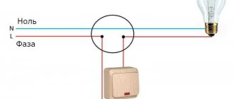
Connection to 220 V network
Connecting a magnetic starter to a 220 V network is the simplest, so it makes sense to start familiarizing yourself with these circuits, of which there may be several.
A voltage of 220 V is supplied directly to the coil of the magnetic starter, which are designated as A1 and A2, which are located in the upper part of the housing, as can be seen from the photo.
Connecting a contactor with a 220 V coil
When a regular 220 V plug with a wire is connected to these contacts, the device will start working after the plug is plugged into a 220 V socket.
We recommend reading: Voltage rectifier: operating principle and types
Using power contacts, it is permissible to turn on/off an electrical circuit for any voltage, as long as it does not exceed the permissible parameters indicated in the product passport. For example, you can apply battery voltage (12 V) to the contacts, with which a load with an operating voltage of 12 V will be controlled.
It should be noted that it does not matter which contacts the single-phase control voltage is supplied to, in the form of “zero” and “phase”. In this case, the wires from contacts A1 and A2 can be swapped, which will not affect the operation of the entire device. It is quite natural that such a connection circuit is used extremely rarely, since it requires direct voltage supply to the coil of the magnetic starter
In this case, there are many options for switching on, using a time relay or a twilight sensor, connecting, for example, street lighting to power contacts. The main thing is that the “phase” and “zero” are nearby
It is quite natural that such a switching circuit is used extremely rarely, since it requires direct voltage supply to the coil of the magnetic starter. In this case, there are many options for switching on, using a time relay or a twilight sensor, connecting, for example, street lighting to power contacts. The main thing is that the “phase” and “zero” are nearby.
380 V connection
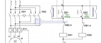
Connecting a contactor operating with 380 volt networks is almost no different from the previous circuit. The only difference lies in the supply of electricity to the coil. In the original version, this problem was solved by using phase (L3) and zero (N), and in the 3-phase version, the connection is made to two phases L2 and L3.
The completed diagram clearly shows the power supply to the starter coil (KM1), connected to phases L2 and L3. The first is routed through a thermal relay (P), and the second through a push-button element for starting (SB2) and braking (SB1) and an auxiliary contact (KM 1), connected to each other in a series circuit.
The action of this scheme is carried out in a certain sequence. When the starting push-button device is pressed, electricity from one of the phases approaches the coil. Under the influence of a field with magnetic properties, the core is retracted, which causes the entire contact group to short-circuit to the connected load. The current voltage, in this case, is 380 V. The released START button does not interrupt the power supply to the circuit, which is provided by an additional movable contact closed at the moment the core is retracted.
In the event of an emergency, the thermal relay is activated. A phase break occurs, the power is turned off and the coil is de-energized. Under the action of springs, the magnetic core returns to its original position. After opening the contacts, the voltage in the emergency area is removed.
Two main types of contactors
Contactors are divided into two types and can be single or double.
A single contactor contains in its design an electromagnetic device that serves to effectively extinguish the electric arc. It is recommended for DC circuits and severe operating conditions such as railway equipment, hydroelectric power plants, induction furnaces, etc.
The contactor must extinguish the arc that occurs when the electrical circuit breaks. In this case, the arc should not be too short (fast) so as not to cause overvoltage in the network and not long so as not to contribute to the destruction of the materials that make up the contactor. The resistance of the arc is directly dependent on the number of free electrons present in the plasma. Ferromagnetic elements that make up the arc suppression chambers and placed in the arc area are necessarily present in the design of the poles. They must turn the arc in the desired direction, this is the so-called magnetic explosion, so they will help cool the environment and the contact connection after the arc is extinguished. To protect against overload, contactors are combined with electronic or thermal overload relays.
Rice. No. 2. Contactor device.
Coil
The contactor coil creates an electromagnetic field in which the moving part of the contactor moves, completing the electrical circuit. Power to the coil comes from AC and DC mains.
Coil AC power supply
In the case of AC power, its value is determined by the impedance of the coil. If the magnetic gap when the coil is turned on is large, the inductance of the coil has a small value, the total resistance will be minimal. The current passing through the coil is maximum and is limited by the resistance value. The amount of load current dictates the pulling force required to turn on the contactor.
When a magnetic circuit closes, its magnetic resistance drops, at the same time its total resistance increases many times, and the current decreases by at least 10 times. The current in the coil decreases with increasing total resistance value, which is caused by decreasing the gap in the contactor, but at the same time it should be enough to keep the electromagnetic coil in the closed state.
DC coil power supply
For DC networks, additional resistance (usually a resistor) is included in the coil supply circuit.
Automation systems use specially designed contactors with electromagnets with low power consumption. They allow direct connection of equipment; these devices are controlled from a discrete output in a direct way. To perform this function, the contactor is equipped with a special electromagnet.
Rice. No. 3. Low power electromagnet circuit.
Additional contact system
The main function of the auxiliary contacts is self-blocking, mutual blocking and interlocking of contacts, as well as indicating the status of the contactor.
Basic modifications of additional contacts
There are three types:
- NO (NO) – normally open contacts (the open state corresponds to an open contact), the closed state – corresponds to the supply of supply voltage to the electromagnet.
- NC (NC) – normally closed contacts: the closed state corresponds to the open position of the contactor, the open contact – power supply to the electromagnet.
- Changeover contacts NO/NC. If the contactor is not receiving power, its contacts will be in the open or closed state. After voltage is applied, their state switches to the opposite.
The additional contact system is equipped with a time delay that can be used after opening or closing the contactor. Time is adjustable.