Electrician 5.8 (download) Intuitive and useful program. The program allows you to: -calculate power using 1ph/3ph current. -calculate current based on 1ph/3ph power. - using the given cross-section and laying conditions, determine the current and power. -calculate voltage losses -calculate short circuit currents -determine the diameter of the wire, cable, cord and special cable. - determine the cross-section of the wire, cable, cord and special cable - check the selected cross-section for: - heating - economic current density - voltage loss - corona - select the cross-section of the wire, cable, cord and special cable for a certain installation and voltage loss for conductors up to 1000 V for a certain length - determine the melting current of the conductor material. - determine resistance. -determine heating. - determine the energy of the electrical circuit. - determine the amount of heat released in the circuit (work). -calculate grounding, both single and office. -calculate soil freezing for grounding and cable laying work -select circuit breakers -calculate the work and select equipment related to electrification. -calculate the price for n number of days m number of kW. - by connected power - by meter 220/380 V (with saving meter values) - the program has a built-in price list for electrical equipment. -It is possible to edit the price list. - basics of electrical safety. -note: documents and tables. -detailed contextual help. -working with price lists in Excel format using a special program CU_prs and much more.
Detailed HELP in the program.
Illumination calculation program
DIALux 4.1 (Russian) (Download 123MB) - requires installation. Allows you to very quickly calculate the degree of illumination and the number of lamps for different conditions. Not everyone will understand it (learn lighting engineering and this program will really make your life easier).
Program for calculating street and road lighting LiN 3.0
Light-in-Night Road (archive) (rar.2007 16.7 Mb) - requires installation. Allows you to calculate street and road lighting. The program is promoted by the Svetotekhnika Trade House
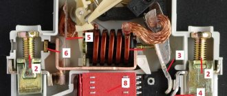
Configurator program for OEZ circuit breakers (Modeon)
Configurator program VA OEZ (Russian) (zip.2008 4.25Mb) - requires installation. The program is very helpful in selecting circuit breakers produced by OEZ - though only the MODEON series.
What is selectivity of relay protection?
Selectivity is one of the four main requirements for relay protection. This requirement is that when a short circuit occurs, only the damaged section must be switched off, while the rest of the circuit continues to operate.
The figure shows that during a short circuit, the current flows through two protections, each of which is started. However, only the protection located closest to the short circuit should operate. If such a condition is met for any network modes, then the protection data is said to be selective.
Main functions
The key objectives of selective protection are to ensure uninterrupted functioning of the electrical system and prevent mechanisms from burning out when threats arise. The only condition for the correct operation of this type of protection is the consistency of the protective units with each other.
As soon as an emergency occurs, the damaged area is instantly identified and switched off using selective protection. At the same time, the working places continue to work, and the disabled ones do not interfere with them in any way. Selectivity significantly reduces the load on electrical installations.
The basic principle of arranging this type of protection lies in the equipment of circuit breakers with a rated current that is less than that of the device at the input. In total, they can exceed the nominal value of the group machine, but individually - never. For example, when installing a 50 A input device, the next device should not have a rating higher than 40 A. The unit located as close as possible to the emergency site will always operate first.
Thus, the main functions of selective protection include:
- ensuring the safety of electrical devices and workers;
- quick identification and shutdown of the area of the electrical system where the breakdown occurred (at the same time, the working areas do not stop functioning);
- reduction of negative consequences for the working parts of electrical mechanisms;
- reducing the load on component mechanisms, preventing breakdowns in the faulty area;
- guarantee of continuous work process and constant high-level power supply.
- support for optimal operation of a particular installation.
What is the time-current characteristic of protection?
Each current protection has its own characteristic, which reflects how quickly the protection operates at a certain current. This characteristic is called time-current.
Typically, overcurrent protection contains several stages, each of which is responsible for its own task.
Overload protection eliminates overload currents that arise due to mechanical faults of motors, the presence of a load above the rated load on their shaft, as well as a decrease in network voltage. This protection senses the smallest emergency currents, but operates with the longest time delays.
Maximum current protection (MCP) protects the connection from all types of short circuits. For most connections 0.4-6(10) kV overcurrent protection is the main protection. The MTZ exposure time ranges from 0 to several seconds.
Current cut-off (TO) protects part of the connection from large short circuit currents. It usually works without a time delay.
The set of stages forms protection characteristic . In the figure above, the protection has a three-stage characteristic.
Household devices
The feasibility of purchasing a reverse power generator for your home remains highly questionable. Manufacturers of such devices simply cannot know what equipment you have at home, when and how long a vacuum cleaner or fan works, what power your refrigerator has, and how many electronics with capacitors and power supplies are in your house. Typically, such devices are calculated, as they say, “by eye” and there can be no talk of 5% savings. The maximum that can be achieved is 0.5 or at most 1%. Considering the price of devices sold on the Internet, with such efficiency, their return on investment is almost zero. So is it worth it?
It is much more effective to apply this principle individually and, based on measurements of the deflection angle, select the required capacity for each more or less powerful equipment with an electric motor.
How to build a selectivity map?
Protective devices are installed sequentially in the network and each has its own characteristics. If we take any protection and consider the circuit in relation to it, then the protections located next to the one under consideration will be called adjacent.
Translating the requirement for selectivity of relay protections into the language of characteristics, we get:
The time-current characteristics of adjacent protections should not intersect and between them there should always be a reserve along the time axis, which is called the selectivity stage
. How to make sure that the protections are selective among themselves?
It is necessary, according to the calculated settings, to plot all the characteristics of adjacent protections on one graph and analyze the graph for intersections of protective characteristics. If there are no intersections and there is always a gap between the curves along the time axis equal to 0.25-0.3 s (selectivity level for modern protections), then the protections are selective among themselves.
This graph is called a selectivity map
It is worth noting that the current cutoffs of adjacent protections on the graph may intersect because their selectivity is ensured by a special choice of operation current (current selectivity).
The characteristics of overload protection and overcurrent protection of adjacent protections should not overlap since their selectivity is ensured by different response time delays (time selectivity)
The analysis of the selectivity map is carried out visually, or, if the construction is carried out in a program, automatically.
Design of networks up to 1000V.
Intrashop electrical networks with voltages up to 1 kV differ from each other in many design features. Network designs depend on the conductor material, insulation methods, environmental conditions, the degree of responsibility of the electrical installation, the distance of the power source to the consumer, the nature of the load (quiet, shock) and other factors.
Based on the methods of insulation, networks with voltages up to 1 kV can be divided into two large groups: those made from busbars and non-insulated conductors and cables. Networks with voltages up to 1 kV, carried out with bare wires, include overhead lines, which have extremely limited use in industrial enterprises. Busbar trunking is made from non-insulated and insulated busbars. Electrical wiring and cable lines refer to networks made of insulated conductors.
When is a selectivity map needed?
Typically, a selectivity map is built for maximum current protection , namely for overload protection, overcurrent protection and current cut-off (TO).
Despite the fact that distance protections are also protections with relative selectivity, a selectivity map is not usually built for them. This is due to the fact that the selectivity of these protections is quite simple to analyze by calculation.
Overcurrent protection is used mainly for connections with voltage class up to 110 kV inclusive.
Thus, we find that the selectivity map should be built for protecting networks of 0.4-110 kV, namely:
- All network protection 0.4 kV (selectivity of circuit breakers and fuse links)
- All protection of 6-10 kV networks (except for differential protection of generators and motors)
- Most of the 35 kV networks (where there are no distance protections)
- Backup protection of step-down transformers with a higher voltage of 110 kV (last element of the selectivity map)
Today, in many projects, especially at 0.4 kV, there is no selectivity map. This is a violation of design standards, leading to non-selective outages of consumers.
Always build a protection selectivity map to avoid such cases!
Comparison of NSAIDs
Some NSAIDs have quite serious side effects, while others do not. This is due to the peculiarities of the mechanism of action: how drugs affect certain types of COX - COX 1, COX 2, COX 3.
In healthy people, COX 1 is found in almost all tissues and organs (for example, in the kidneys and gastrointestinal tract), where it performs its most important function. With the help of COX-synthesized prostaglandins, the integrity of the intestinal and gastric mucosa and adequate blood flow in it are maintained, the secretion of hydrochloric acid is reduced, the pH is increased, the secretion of mucus and phospholipids is ensured, and cell proliferation (reproduction) is stimulated.
NSAID drugs that inhibit COX 1 help reduce the concentration of prostaglandins not only in the inflammatory focus, but throughout the human body, resulting in the development of negative consequences.
In healthy tissues, COX 2 is usually found in small quantities or is completely absent. An increase in its level is observed directly during inflammation or in the inflammatory focus itself. NSAID drugs that selectively inhibit COX 2 are most often taken systemically, but their action is directed specifically at the site of inflammation, helping to reduce the inflammatory process there.
Despite its contribution to the development of fever and pain, COX 3 does not participate in inflammatory processes. The action of certain NSAIDs is aimed at this type of enzyme, but at the same time they have a weak effect on COX 1 and COX 2. According to some experts, COX 3 is not an independent isoform of the enzyme, but is a variant of COX 1, but this statement is not currently true confirmed by additional studies.
Basic rules for constructing a selectivity map
- All protection settings must be reduced to the same voltage
- Choose the construction scale correctly so that all boundary points are visible. To fulfill this condition, a logarithmic scale is often used.
- The selectivity map displays not only the protective characteristics, but also the boundary (minimum and maximum) short circuit currents at the design points of the circuit.
Advice
Avoid using colors to differentiate curves because most modern designs are printed on black and white laser printers. Better use geometric marks (circles, triangles, crosses, etc.)
Next time we will build a selectivity map to protect a 10/0.4 kV power transformer and its adjacent protections using the Greedis-KS program
Principle of logic
To implement circuits using this principle, digital relays are needed. The relays are connected to each other by a twisted pair line, a fiber optic cable, or via a telephone line (using a modem). With the help of such lines, information is received (transmitted) to the dispatch console from different objects and between the relays themselves.
The principle of logic in a radial network
The given Picture 9 explains the principle of operation of the logic. Each of the 4 digital relays uses a current setting equal to the most recent sensitive stage. This stage has an operating time of 0.2 s. Logical selectivity implies the possibility of blocking the relay with a LO (logical standby) signal. This signal is supplied through the channel from the previous protection relay. Each of the relays can transmit such signals in transit.
As can be seen from the figure, during a short circuit at point K1, all other relays, from the LO signal supplied by relay K1, will be on hold. Relay K1 will operate and shut down. In the event of a short circuit at point 2, relay K4 will operate in the same way.
Such schemes for constructing logical control are demanding on the reliability of communication lines between elements.
Methods of construction and types of selective protection systems
Based on the listed principles, the main methods and types of design of selective protection systems are identified.
Current selectivity
Circuit breakers with different current thresholds are sequentially installed in the network.
The principle of constructing current selectivity
An example would be the network of an ordinary apartment or private house, when a 25A input circuit breaker is installed in the distribution board, followed by an intermediate 16A circuit breaker. Automatic devices with an operating limit of 10A are installed on socket lighting groups or household appliances with a separate line. At the same time, the temporary and other response thresholds for these protective switches may be the same or vary depending on the nature of the load.
Current selective protection circuit
Selectivity by time interval of protection operation
In this case, the construction of protection is carried out according to the same principle as with current protection, only the determining parameter for selectivity is the operation time of the circuit breakers when the threshold current value is reached.
Time selective protection circuit
The input circuit breaker in the distribution board is set to an operating interval of 1 second, the intermediate switch has an interval of 0.5 seconds, and before the load itself there are circuit breakers with an operating interval of 0.1 seconds.
- Time-current protection is a set of elements taking into account threshold trip values for current and time, practically a combined option for selecting the parameters listed above;
- Zone protection - when the selective principle of protection is applied to a separate section of the circuit;
An example of constructing a zonal defense scheme
The logical principle of constructing selective protection provides for the presence of a processor that receives signals from all protection elements connected in series in the circuit. Based on this data, the device makes a decision and sends a signal to disable the protection element in the area where the threshold of one of the monitored parameters is exceeded;
Selective protection circuit built on a logical principle
Directional selectivity - when protection elements are installed sequentially in the direction of the current, the voltage vector direction point is formed by a phase shift in voltage. Thus, the relay reacts to changes in voltage and direction of current not only in the area where the protection is installed, but also along the entire circuit line from the power source.
If there is a short circuit on the first line, it will be turned off, while the second line will continue to work and, conversely, if a fault occurs on the second line, the first line will not turn off. The disadvantage of this method is that, in addition to circuit breakers, it is necessary to install voltage transformers on each phase of the line.
Differential principle of construction of selective protection
This method is used in circuits where a load that consumes large electrical power is connected. Current control is carried out by voltage transformers only in the A-B section. In fact, processes are controlled on a short section of the network where the load is connected; when threshold values are exceeded, specific equipment is turned off without affecting other areas.
Differential protection circuit
The advantage of this method is its high speed and sensitivity to changes in parameters, but the disadvantage is the high cost of the equipment.
All of the listed methods of the selective principle of constructing protection make it possible to solve a number of problems during the operation of electrical circuits:
- Maintain the operability of serviceable areas during the occurrence of a malfunction in adjacent areas;
- Automatic detection of the fault location and disconnecting it from the working network;
- Ensuring the safety of electrical installation personnel.
When constructing selective protection, it is necessary to comply with the basic principles: all elements are set to the same voltage, and at control points the smallest and largest values of the parameters during a short circuit must be taken into account.