When arranging a home electrical network or doing electrical repairs yourself, you need to figure out how to connect the lamp through a switch, the order of which depends on a variety of factors. In this case, not only the type of switch must be taken into account, but also the class of the lighting device connected to the household system. To understand the features of these electrical procedures, you should understand how to properly connect the device in each specific case. The following options are possible:
- Using a single-key device.
- Option for connecting to a two-key switch.
- The same thing, but only concerning a different type of device (with three keys, for example).
- Power supply to the lamp from any outlet available in the room, implemented by laying a separate line from it.
But it is also important to familiarize yourself with the methods of connecting several light bulbs to one switch, as well as the options when LED or spotlights are connected to them.
Connection via one-key switch
The connection diagram for a luminaire via a single-key switch is the simplest of the considered range of possible load switching methods. To implement it, you will have to perform the following sequence of mandatory operations:
- First of all, you will need to remove the supply voltage of 220 volts from this line (this is easiest to do using an input or linear machine).
- After this, you need to make sure that it is absent using an indicator screwdriver or a special measuring device - a multimeter (it is switched on in the mode of measuring alternating voltages at a limit of up to 750 volts).
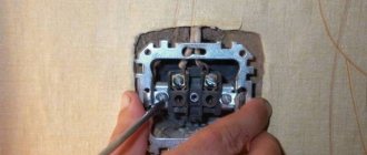
- Then you need to remove the key from the switch by prying it from the side with a thin-bladed screwdriver.
- Next, you need to fix the switch body in a niche prepared in advance in the wall and carefully bring the two wires connected to it out.
- Inside the open base, you need to find two contacts, to one of which (the bottom) the wire suitable from below is connected, and to the second (top) the end that goes directly to the lighting device is connected.
Important! The procedure for connecting wires to the switch is strictly regulated by the requirements of the PUE.
As a result of these manipulations, a switch with one key will be connected to a phase wire break.
Thanks to this circuit, it will be possible to supply 220 volt power directly to the lamp.
Nuances of twist formation
When twisting two wires, their exposed ends are folded in an “X” shape so that the intersection is at the beginning of the insulation. Then the ends of the veins are pinched with your fingers and twisted as much as possible. Next, the process is helped with pliers.
Three or more wires are connected in the same way. If the connection comes out both long and flexible, fold it in half, pressing it with pliers. A shorter twist requires less electrical tape.
The longer the cleaned tails of the wires are, the easier it will be to make twists, and the more reliable the contact will be - and the excess can always be trimmed
The insulating tape begins to be applied from the factory insulation of the twisted wires to the width of the tape. After passing in one layer until the end of the bare tails, a couple more turns are made, as if wrapping up the air. This “void” is bent back into a twist - a protected end is obtained, and the second row is wound up with the obligatory approach to the main insulation of the cores.
Connecting luminaires to a double switch
A double switch is a device of a special design, in which instead of one changeover contact, two are built in at once.
Additional information: In terms of their design, they are completely identical, but each is used for its own purpose.
Before connecting the double switch, you will need to pay attention to the following detail. In this case, the connection principle and the procedure for carrying out operations remain the same as discussed in the previous section. The only difference is the number of wires connected to the upper terminals. When making connections, the following points must be taken into account:
- The phase wire must be located at the bottom and connected to the double switch from the bottom terminal.
- On the body of a typical device - a double switch - there are two contacts on top.
- A wire from a separate group of illuminators (light bulbs) is connected to each of them.
Once you have managed to connect a two-key switch, you can use it to turn on either one group of illuminators or another. If necessary, by pressing both keys at once, you can light all the lamps at the same time.
Application of junction box
Cables and wires do not go directly from the panel to electrical appliances, from switches to light bulbs. All outgoing and incoming lines of electrical equipment are found in specific installation units called branch boxes. There they communicate in a certain way.
Most often, boxes have empty space inside. The wires of different lines are then connected to each other using twists. To ensure reliability, it is recommended to treat the tails of the connections with special welding. Copper conductors can simply be soldered.
Before laying inside, open contacts are insulated from each other with cotton tape. You can screw special insulating clamps onto the twisted wires. Here, insulating tape is no longer needed.
Do not use PVC-type electrical tape to insulate twists - over time it will stick to the contacts so that it will be difficult to remove if necessary.
If the box is equipped with screw terminals, the contacts are then made using them. Such devices allow you to connect aluminum and copper conductors. Clamp terminals can be used, but this is only if there is sufficient space for laying the ends of the wires connected by them.
Connecting the illuminator from an outlet
In a situation where the switch is installed in a new place (in the absence of a special niche), it can be mounted directly on the wall and powered from a nearby outlet. In this case, before connecting the lamp through the switch, it is necessary to extend the phase and zero from it, as shown in the photo below. In certain conditions, one phase is sufficient for this, since the neutral wire is already connected to the wall lights from the junction box.
Before connecting lamps with a switch from the nearest outlet, you need to familiarize yourself with the features of this procedure. The order of its execution looks like this:
- First, an indicator screwdriver is taken, with which the phase wire is determined and remembered, from which the wire is subsequently routed to the switch (it can be located either on the right or on the left).
- After this, the dangerous voltage of 220 volts is removed from the line, in which a switch is installed along with sockets, using an automatic machine.
- To be sure of its absence, it is advisable to check it with an indicator screwdriver.
- Before connecting the lamp through the switch from the socket, you need to remove the decorative cover from it, under which there are two contacts.
- A conductor of the required length is connected to one of them (phase) and routed to a single switch.
Upon completion of the preparatory procedures, the wire coming from the outlet is supplied to the switch mounted on the wall with the cover removed (it is connected to its lower terminal). Another conductor is pulled from the top contact towards the lamp, which is placed in a cable channel or tubular corrugation for aesthetics. In the same way, you can close the wire in the area from the outlet to the switch.
Connection diagram for a luminaire via a switch in a combined socket-switch unit in one housing:
Connection using an electrical junction box
Work begins after the power supply cable is de-energized. Only this will guarantee that the master will not suffer from electric shock if he touches a bare wire or uninsulated contact. It is important to define the “phase”.
Mechanical rupture of the “zero” core will lead to injury. If you touch it and the cable under load at the same time, the body becomes a conductor. The result is electric shock.
An indicator or tester will indicate which core has voltage. It should be disconnected at the entrance to the premises (house, apartment, office, workshop). Judging by the diagram, the switch is located between the input and the lamp. Moreover, the connection is made in such a way that in the “Off” position the current supply wire is broken, while the “neutral wire” remains intact. The diode on the indicator will light up if you touch it with a metal tip.
The functional significance of the distribution box is to distribute the current between the socket group, lighting, and other adjacent rooms. One of the branches is the input of power electrical cables stretched from the switchboard, an electric meter with “plugs” or “automatic machines”. In most cases, the developer is responsible for this, and residents, when carrying out repairs, have the right only to change the wiring, lay new branches, and change the wiring diagram for lamps and sockets.
Connecting spotlights
If it is necessary to use spotlights in an apartment, it is assumed that they can be supplied with either a standard mains voltage of 220 volts or reduced to a safe level of 12 volts.
The specific connection diagram for spotlights is selected taking into account the type of illuminators used, designed for the appropriate voltage.
Before connecting spotlights, you should pay attention to the fact that the order of their switching does not differ from the standard method.
Connection without power supply
Modern LED light bulbs are now produced at a voltage of 220 volts, since an electronic converter is installed inside the lamp, providing power to the LEDs at a reduced voltage. You can familiarize yourself with the design of an LED lamp in this article. The connection diagram for spotlights with 220-volt LED lamps is exactly the same as with conventional lamps.
Connection with power supply
When installing spotlights or LED strips, a transformer is additionally introduced into the circuit, reducing the voltage from 220 to 12 Volts. Now these devices are called power supplies , produced for various voltages and load power.
Please note: When connecting two or more points, the power supply is installed immediately after the switch (see diagram below).
Connection diagram for a group of spotlights with one step-down transformer:
Connection diagram for a group of spotlights with a transformer for each light:
Usually, to connect spotlights, an electronic converter (aka power supply) is selected, which compares favorably with other devices with the following advantages:
- Small size and light weight.
- Built-in short circuit protection.
- Smooth increase in voltage when turned on, extending the life of the bulbs.
- Ability to regulate and maintain stable power supply.
In addition, these devices are characterized by extremely low noise levels generated during operation of auxiliary equipment.
We invite you to watch a training video on the topic: “How to properly install spotlights.”
Tool for getting the job done
In the process of performing electrical work, a home handyman will need a set of the following installation tools:
- Sharp knife.
- Pliers (pliers).
- Side cutters.
- Slotted screwdrivers, thin and medium, possibly Phillips medium.
Electrical tape may be required to insulate the wire connections inside the junction box or light housing. In these cases, it is recommended to use CB tape. Over time, it does not melt or stick to the constantly heating contacts it insulates, but only dries out. If necessary, crumble well with pliers.
Before you begin the simplest installation, draw a diagram for connecting electrical appliances in a way that will be clear to you, and think over the procedure
It’s great if you have a special wire stripping tool - a stripper or wire cutters with slots for stripping insulation. In the absence of such devices and a large amount of work, you can get by with a folk remedy by modifying the side cutters.
To do this, use a file to make opposite cuts in the cutting edges closer to the hinge, which together should form a hole slightly larger than the diameter of the exposed wire strand.
Connecting LED strips and lamps
The connection diagram for LED-based illuminators is no different from the previously discussed options. The only thing you should pay attention to before connecting an LED strip or lamp is the use of a voltage converter (power supply) or driver.
As in the case of spotlights, in this situation the power supply is installed immediately after a single-key, two-key or three-key switch (photo below).
Each individual strip or LED device is connected through its own converter, which allows you to control its operation independently of the others. Several lighting strips can be connected to “powerful” adapters at once.
Installation of LED lamps for 220V AC circuits
LED light bulbs consist of the following components:
- Base (E27, E14, E40 and so on) for screwing into the socket of a lamp, sconce or chandelier;
- Dielectric gasket between the base and the housing;
- A driver on which a circuit is assembled to convert alternating voltage into a constant voltage of the required value;
- A radiator that serves to remove heat from the LEDs;
- A printed circuit board onto which LEDs are soldered (sizes SMD5050, SMD3528, and so on);
- Resistors (chips) to protect LEDs from pulsating current;
- Light diffuser to create a uniform light flux.
Safety conditions
Installation of such a circuit is not particularly difficult. However, for successful work, a number of safety requirements must be observed. How to do the job right:
- Be sure to turn off the power to the apartment/building/floor before starting work.
- Only by the position of the control keys on one of the switches, it will not be possible to determine whether the lighting device is on or off. If you decide to change a light bulb, be sure to turn off the light supply at the switchboard before doing so. Otherwise, you risk your health. The lamp may explode right in front of your eyes.
- If you have to twist the ends of the wires, for reliability they should be soldered and secured with electrical tape.
- The fittings and branch block must be secured as firmly as possible.
- The cable cross-section must be selected based on the power of the incoming electricity and the lamp itself.
Schemes of serial and parallel connections of light bulbs
For parallel and serial connections of light bulbs, special circuits are used. To make it easier to understand, similar images of elements are used. For example, inputs and outputs are indicated by a vertical bar and a "+" or "-". Electrical elements (light bulbs, lamps) - a crossed out circle, resistors - an empty rectangle.
Symbolic images on electrical diagrams are of the same type, so it is more familiar and convenient to read the order in which the elements are connected
Connecting a light bulb is one of the easiest tasks for an electrician. Another question is organizing a common circuit in a living room or assembling a chandelier with several incandescent lamps. To avoid difficulties during operation, to prevent breakdowns as much as possible and to simplify future network repairs, it is necessary to familiarize yourself in advance with possible connection diagrams and take into account their advantages and disadvantages.
How to phasing inputs with incandescent light bulbs
Let's say you need to connect two three-phase inputs (380V) in parallel from one power source. You don't have a voltmeter, multimeter or tester at hand. What to do?
After all, if you mix the phases, you can easily create an interphase short circuit! And here, too, the sequential assembly of two light bulbs at once will help.
Assemble them according to the very first diagram given and connect one end of the power cord to input No. 1. 1, the other end alternately touches the wires of input n. 2.
For phases of the same name, the lamps do not turn on (for example, input fA n. 1 - input fA n. 2).
And with several (fA input No. 1 - PV input No. 2) - they light up.
You will never succeed in such an experiment with only one lamp, since it will instantly explode from a voltage above 380V for it. And when assembled in series with two products of the same power, the voltage will be supplied within the normal range. But the best and most practical application is to use this circuit not for lighting, but for heating. That is, your light sources will primarily work not as lamps, but as heaters.
Read about how to make such a simple and uncomplicated infrared heater in the article at the link below.
Something similar is often used in incubators.
