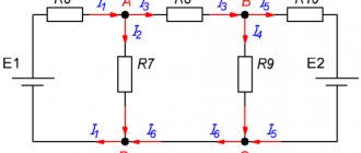
Symmetrical
Symmetrical AC circuits involve connecting 3 phases from a source (generator) to three receivers.
This creates completely independent three-phase circuits. In this case, a star connection of the three phases of the generator is used. For symmetrical circuits the following requirements must be met:
- The amplitude must be the same for all phases.
- The emf must have a shear angle of 120 degrees.
- The angular frequencies must be equal.
The principle of alternating EMF in time is also taken into account. If the generator rotor rotates clockwise (right rotation), then direct type alternation occurs (A, B, C). Such a system is considered symmetrical.
If the rotor rotates counterclockwise (left rotation), the alternation is considered reverse (A, C, B), but the overall EMF system remains symmetrical.
For symmetrical circuits, the vector histogram calculation below is used.
Ohm's law - the basis of electrical engineering
This basic equation, used to study electrical circuits, was obtained experimentally by Georg Simon Ohm. He was born in Erlangen Germany in 1787 and entered the university of that city in 1805, where he received his doctorate. Georg taught mathematics in schools and conducted physics experiments in the school physics laboratory, trying to understand the principles of electromagnetism.
In 1827, he published papers describing a mathematical model of how circuits conduct heat in the works of Fourier. Ohm obtained experimental data on the basis of which he was able to formulate his law for the first time on January 8, 1826. He established that the potential difference between two points in a circuit is equal to the product of the current between them and the total resistance of all electrical devices. The greater the battery's voltage, or its total electrical potential difference, the greater its current will be. Likewise, with more resistance it will be less.
But his research did not find proper understanding and Georg left his work in Cologne. Only in 1833 did he receive a professorship in Nuremberg. Ohm's findings served as a catalyst for the latest research in electricity. In 1841, the scientist was awarded the Copley Medal, and in 1872, the "Ohm" was adopted as a unit of resistance in electrical circuits.
Ohm's Law for a complete electrical circuit describes the flow of current through conductive metals when different voltage levels are applied. Some materials, such as electrical wires, have little resistance to current flow—this type of material is called a conductor.
Important! In other cases, the material may prevent current flow but still allow it to be used. In electrical circuits, these components are often called resistors. There are materials that practically do not allow current to pass through, they are called insulators.
Asymmetrical
Asymmetrical circuits imply a difference in resistance on each phase. A similar difference can occur if one conductor or neutral breaks, its poor contact, or short circuit. For example, when the neutral wire breaks, the following occurs:
- Increasing neutral resistance.
- Complete absence of conductivity.
- Increase in voltage.
- Maximum phase voltage distortion.
When calculating an asymmetrical circuit, the calculation of the connection between the source and receivers according to the star circuit is also taken into account. The difference lies in the additional calculation of displacements, phase shifts and resistance values of each conductor.
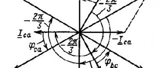
Below is a phasor diagram of an unbalanced circuit.
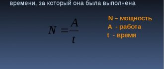
Power measurement
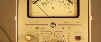
Active power in networks is measured using a wattmeter
Digital wattmeter Analog wattmeter
Depending on the load connection diagram and its nature (symmetrical or asymmetrical), the connection diagrams of the devices may vary. Consider the case with a symmetrical load:
Scheme for connecting a wattmeter with a symmetrical load
Here the measurement is carried out in only one phase and then multiplied by three according to the formula. This method allows you to save on instruments and reduce the dimensions of the measuring setup. It is used when greater measurement accuracy in each phase is not needed.
Measurement with unbalanced load:
Scheme for connecting a wattmeter with an asymmetric load
This method is more accurate, since it allows you to measure the power of each phase, but it requires three instruments, large overall dimensions of the installation and processing of readings from three instruments.
Measuring in a circuit without a neutral conductor:
Scheme for connecting a wattmeter in the absence of a neutral wire
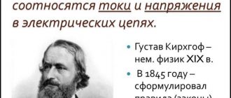
This circuit requires two devices. This method is based on Kirchhoff's first law
IA+IB+IC=0. It follows from this that the sum of the readings of two wattmeters is equal to the three-phase power of this circuit. The vector diagram for this case is shown below:
Vector diagram for switching on two wattmeters for different types of load
We can conclude that instrument readings depend not only on the magnitude, but also on the nature of the load.
From the diagram it follows that we can determine the instrument readings analytically:
Having analyzed the obtained result, we can conclude that, with a predominance of active load (φ=0), the measurement results of wattmeters are identical (W1=W2). With active and inductive (RL), the readings of W1 are less than W2 (W12); with φ>600, the readings of W1 are generally negative (W1<0).
With active and capacitive (RC) and W1>W2, and with φ<-600 readings W2 <0.
With the modern development of technology, digital wattmeters have appeared. Unlike analog ones, they are smaller in size, much lighter and less bulky. Moreover, digital wattmeters can record current, voltage, measure cosφ in the network, and more. They allow you to monitor various quantities in real time and issue warnings when they deviate. This is very convenient and there is no need to measure current, voltage, and then calculate it all mathematically. The digital wattmeter is enclosed in a housing and is connected (for household consumers) in the most usual way - like a regular consumer - by plugging a plug into a socket.
Building a chart
The vector diagram basically assumes the following values:
- Reference point N for all three separate phases.
- Vector direction of ABC as individual conductors of a voltage source (generator). Each vector has a given length equal to its voltage.
- The end of the vectors AB, BC, CA, as voltage receivers.
These values are supplemented by a unit of time during which the current, at a certain voltage and strength, reaches the receivers. Based on the construction, we get the result: UAB=UBC=UCA.
This means that if the phase voltage system is symmetrical, then the linear system is also symmetrical and equal, and in addition has a shift of 120 degrees. This is a simple definition of the vector of a three-phase circuit.
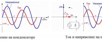
Alternating current is a sine wave that can be graphically superimposed on a coordinate axis. In this case, the vector has an angular rotation speed, which is equal to the angular frequencies of the current. When constructing, it is also necessary to take into account the fact that the vector is a graphical representation of the vibration amplitude, in which the vibration angle is equal to the initial reference point.
For example, the coordinate axis is set to 0. The offset angle is also known. Next, it is worth drawing the vector “Im”, which determines the direction of current movement. When constructing a vector using these values, the lead, lag, or phase shift parameters will become visible. This way you can visually see the difference in values on each conductor of the circuit.
A three-phase circuit is a special case of multiphase electrical systems, which are a set of electrical circuits in which EMFs of the same frequency operate, shifted in phase relative to each other by a certain angle. Note that usually these EMFs, primarily in power engineering, are sinusoidal. However, in modern electromechanical systems, where frequency converters are used to control actuator motors, the voltage system is generally non-sinusoidal. Each part of a multiphase system characterized by the same current is called a phase,
those. phase is a section of the circuit related to the corresponding winding of the generator or transformer, line and load.
Thus, the concept of “phase” has two different meanings in electrical engineering:
- phase as an argument of a sinusoidally varying quantity;
- phase as an integral part of a multiphase electrical system.
The development of multiphase systems was driven by history. Research in this area was driven by the requirements of developing production, and advances in the development of multiphase systems were facilitated by discoveries in the physics of electrical and magnetic phenomena.
The most important prerequisite for the development of multiphase electrical systems was the discovery of the phenomenon of a rotating magnetic field (G. Ferraris and N. Tesla, 1888). The first electric motors were two-phase, but they had poor performance. The three-phase system turned out to be the most rational and promising, the main advantages of which will be discussed below. A great contribution to the development of three-phase systems was made by the outstanding Russian electrical engineer M.O. Dolivo-Dobrovolsky, who created three-phase asynchronous motors, transformers, proposed three- and four-wire circuits, and therefore is rightfully considered the founder of three-phase systems.
The source of three-phase voltage is a three-phase generator, on the stator of which (see Fig. 1) a three-phase winding is placed. The phases of this winding are arranged in such a way that their magnetic axes are shifted in space relative to each other by an electric amount. glad. In Fig. 1, each stator phase is conventionally shown as one turn. The beginnings of the windings are usually designated by capital letters A, B, C, and the ends by capital letters x, y, z, respectively. The EMF in the stationary stator windings is induced as a result of the intersection of their turns by the magnetic field created by the field winding current of the rotating rotor (in Fig. 1, the rotor is conventionally depicted as a permanent magnet, which is used in practice at relatively low powers). When the rotor rotates at a uniform speed, periodically changing sinusoidal EMFs of the same frequency and amplitude are induced in the windings of the stator phases, but differ due to a spatial phase shift of rad. (see Fig. 2).
Three-phase systems are currently most widespread. All large power plants and consumers operate on three-phase current, which is associated with a number of advantages of three-phase circuits over single-phase ones, the most important of which are:
— economical transmission of electricity over long distances;
— the most reliable and economical electric drive that meets the requirements of an industrial electric drive is an asynchronous motor with a squirrel-cage rotor;
— the possibility of obtaining a rotating magnetic field using stationary windings, on which the operation of synchronous and asynchronous motors, as well as a number of other electrical devices, is based;
— balance of symmetrical three-phase systems.
To consider the most important property of balance
three-phase system, which will be proven later, we introduce the concept of symmetry of a multiphase system.
The EMF system (voltages, currents, etc.) is called symmetrical,
if it consists of m EMF vectors (voltages, currents, etc.) of equal magnitude, shifted in phase relative to each other by the same angle. In particular, the vector diagram for a symmetrical EMF system corresponding to a three-phase sinusoidal system in Fig. 2, is shown in Fig. 3.
| Fig.3 | Fig.4 |
Of the asymmetrical systems, the two-phase system with a 90-degree phase shift is of greatest practical interest (see Fig. 4).
All symmetrical three- and m-phase (m>3) systems, as well as a two-phase system, are balanced.
This means that although in individual phases the instantaneous power pulsates (see Fig. 5, a), changing during one period not only the magnitude, but in the general case also the sign, the total instantaneous power of all phases remains constant throughout the entire period of the sinusoidal EMF (see Fig. 5,b).
Balance is of utmost practical importance. If the total instantaneous power pulsated, then a pulsating torque would act on the shaft between the turbine and the generator. Such variable mechanical load would have a detrimental effect on the power generating plant, shortening its service life. The same considerations apply to multiphase electric motors.
If symmetry is broken (Tesla's two-phase system, due to its specificity, is not taken into account), then balance is also broken. Therefore, in the energy industry they strictly ensure that the generator load remains symmetrical.
Connection diagrams for three-phase systems
A three-phase generator (transformer) has three output windings, identical in the number of turns, but developing an EMF shifted in phase by 120°. It would be possible to use a system in which the generator winding phases were not galvanically connected to each other. This is the so-called disconnected system.
In this case, each phase of the generator must be connected to the receiver with two wires, i.e. there will be a six-wire line, which is uneconomical. In this regard, such systems are not widely used in practice.
To reduce the number of wires in the line, the generator phases are galvanically connected to each other. There are two types of connections: in a star
and
into a triangle.
In turn, when connected in a star, the system can be
three-
or
four-wire.
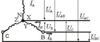
Star connection
In Fig. Figure 6 shows a three-phase system when the generator and load phases are connected in a star. Here wires AA', BB' and CC' are linear wires.
Linear
called the wire connecting the beginning of the phases of the generator and receiver windings.
The point at which the ends of the phases are connected into a common node is called neutral
(in Fig. 6 N and N' are the neutral points of the generator and load, respectively).
The wire connecting the neutral points of the generator and receiver is called neutral
(shown in dotted line in Fig. 6).
A three-phase system when connected in a star without a neutral wire is called three-wire,
with a neutral wire -
four-wire.
All quantities related to phases are called phase variables,
to the line -
linear.
As can be seen from the diagram in Fig. 6, when connected in a star, the linear currents and are equal to the corresponding phase currents. If there is a neutral wire, current flows in the neutral wire. If the system of phase currents is symmetrical, then. Consequently, if the symmetry of the currents were guaranteed, then the neutral wire would not be needed. As will be shown below, the neutral wire ensures the maintenance of symmetry of voltages across the load when the load itself is unbalanced.
Since the voltage at the source is opposite to the direction of its EMF, the phase voltages of the generator (see Fig. 6) act from points A, B and C to the neutral point N; — phase load voltages.
Line voltages act between line wires. In accordance with Kirchhoff's second law for linear voltages, we can write
| ; | (1) |
| ; | (2) |
| . | (3) |
Note that it is always the sum of voltages along a closed loop.
In Fig. Figure 7 shows a vector diagram for a symmetrical voltage system. As its analysis shows (the rays of phase voltages form the sides of isosceles triangles with base angles equal to 300), in this case
| (4) |
Usually in calculations it is taken. Then for the case of direct phase rotation
, (with
reverse phase alternation,
the phase shifts y and change places). Taking this into account, based on relations (1) ... (3), complexes of linear voltages can be determined. However, with voltage symmetry, these quantities are easily determined directly from the vector diagram in Fig. 7. Directing the real axis of the coordinate system along the vector (its initial phase is zero), we count the phase shifts of linear voltages with respect to this axis, and determine their modules in accordance with (4). So for linear voltages we get: ; .
Triangle connection
Due to the fact that a significant part of the receivers included in three-phase circuits are asymmetrical, it is very important in practice, for example, in circuits with lighting devices, to ensure the independence of the operating modes of individual phases. In addition to the four-wire circuit, three-wire circuits also have similar properties when the receiver phases are connected in a triangle. But the generator phases can also be connected into a triangle (see Fig. 8).
For a symmetric EMF system we have
.
Thus, in the absence of load in the generator phases in the circuit in Fig. 8 currents will be zero. However, if you swap the beginning and end of any of the phases, then a short circuit current will flow in the triangle. Therefore, for a triangle, the order of connecting the phases must be strictly observed: the beginning of one phase is connected to the end of another.
The diagram for connecting the phases of the generator and receiver into a triangle is shown in Fig. 9.
It is obvious that when connected in a triangle, the line voltages are equal to the corresponding phase voltages. According to Kirchhoff's first law, the connection between the linear and phase currents of the receiver is determined by the relations
Similarly, line currents can be expressed through the phase currents of the generator.
In Fig. Figure 10 shows a vector diagram of a symmetrical system of linear and phase currents. Its analysis shows that with current symmetry
| . | (5) |
In conclusion, we note that in addition to the considered star-star and delta-delta connections, star-delta and delta-star circuits are also used in practice.
Literature
- Fundamentals
of circuit theory: Textbook. for universities / G.V. Zeveke, P.A. Ionkin, A.V. Netushil, S.V. Strakhov. –5th ed., revised. –M.: Energoatomizdat, 1989. -528 p. - Bessonov L.A.
Theoretical foundations of electrical engineering: Electric circuits. Textbook for students of electrical engineering, energy and instrument engineering specialties of universities. –7th ed., revised. and additional –M.: Higher. school, 1978. –528 p.
Test questions and tasks
- What is the operating principle of a three-phase generator?
- What are the main advantages of three-phase systems?
- What systems have the property of balance, how is it expressed?
- What connection diagrams exist in three-phase circuits?
- What relationships between phase and linear quantities take place when connected in a star and in a triangle?
- What happens if you swap the beginning and end of one of the generator phases when connected in a triangle, and why?
- Determine the linear voltage complexes if, when connecting the generator phases into a star, the beginning and end of the phase C winding are swapped.
- In the diagram in Fig. 10 (three-phase current system is symmetrical). Determine the complexes of the remaining phase and linear currents.
- What connection schemes ensure autonomous operation of load phases?