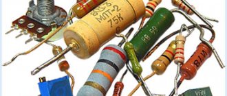
is a passive element of an electrical circuit that has a certain or variable value of electrical resistance. Unlike active elements, passive elements do not have the ability to control the flow of electrons.
Resistors are popularly called “resistors” or simply “resistance”. Resistors are responsible for linearly converting current into voltage and vice versa, as well as for limiting current and absorbing electrical energy.
Resistor is one of the most popular components and is used in most electronic devices.
Why is a resistor needed in an electrical circuit?
A clear example of how a resistor works
Using a resistor in an electrical circuit, the current is limited, obtaining its desired value. According to Ohm's law, the greater the resistance at a stable voltage, the less the current.
Ohm's law is expressed by the formula U = I*R, in which:
- U – voltage, V;
- I – current strength, A;
- R – resistance, Ohm.
Also resistors work as:
- current to voltage converters and vice versa;
- voltage dividers, this property is used in measuring devices;
- elements to reduce or completely remove radio interference.
Principle of operation
When purchasing a part, you need to understand exactly how a resistor works. Any conductor component has certain characteristics due to its internal structure. When an electric current flows through a conductor, charged particles passing through its structure lose their energy reserve, releasing it outward and heating the substance. It is known that the voltage value is equal to the product of the current passing through the conductor and the resistance of the material from which it is made. What does a resistor do? Since it contains a component with a very high resistance to current, when the latter passes through the element, the voltage decreases and some of the power is released in the form of heat.
Main characteristics of resistors
The parameters that need to be taken into account when choosing a resistor depend on the nature of the circuit in which it will be used. The main characteristics include:
- Nominal resistance.
This value is measured in Ohms, 1 kOhm (1000 Ohms), 1 MOhm (1000 kOhms), 1 GOhm (1000 MOhms). - Maximum power dissipation
is the maximum power that an element is capable of dissipating during long-term use. In the diagrams, the rated dissipation power is indicated only for powerful rechargers. The higher the power, the larger the part size. - Accuracy class.
Determines how much the actual resistance value may differ from the declared value.
If necessary, take into account the maximum operating voltage, excess noise, resistance to temperature and moisture, and voltage factor. If the part is planned to be installed in a device operating at high and ultra-high frequencies, parasitic capacitance and parasitic inductance must be taken into account. These values should be minimal.
Scope of application of resistors
The resistor plays a vital function in the operation of electrical systems. For example, it is able to control the distribution, power and other characteristics of electricity in a car. A resistor of any size located in the heating system allows you to precisely regulate the amount of heat supplied.
An element located in the LEDs allows you to adjust the lighting intensity. Consequently, this mechanism allows us to more accurately regulate the operating parameters of the equipment. Otherwise, we would have to use a pre-established mode of operation of the equipment without the possibility of changing it.
Installation method
According to installation technology, resistors are divided into output and SMD.
Output resistors
Radial output resistor
Axial output resistor
Designed for installation through a printed circuit board. The leads can be located axially or radially. Such parts were used in old audio and video equipment. Now they are used in simple devices and in cases where the use of SMD resistors is impossible for some reason.
The design of output resistors can be made of wire, metal film or composite.
What does a wirewound resistor consist of?
In wirewound resistors, the resistive component is a wire wound around a core. Bifilar winding (two parallel wires insulated from each other, or a regular two-core wire) reduces parasitic inductance. Leads made of stranded copper or brass plates are connected to the ends of the winding. To protect against moisture, mechanical damage and contamination, wire cuts are coated with inorganic enamel that is resistant to elevated temperatures.
What is the difference between a metal film resistor and a wirewound resistor?
In a metal film resistor, the resistive element is not a wire, but a film made of a metal alloy. The resistive components (wire or film) in the resistor are made of alloys with high resistivity: manganin, constantan, nichrome, nickel.
SMD resistors
SMD resistors (or chip resistors) are designed for surface mounting and do not have pins. These miniature parts of low thickness are made in rectangular or oval shapes. They have small contacts soldered into the surface. Their advantages are saving space on the board, simplifying and speeding up the board assembly process, and the ability to use them for automated installation.
SMD resistors are manufactured using film technology. They can be thin- or thick-film. A resistive thick or thin film is applied to an insulating substrate. The substrate performs two functions: a base and a heat-removing component.
What are chip resistors made of?
Thin-film elements, which have special requirements for moisture resistance, are made of nichrome. In the production of thick-film models, ruthenium dioxide, lead and bismuth ruthenites are used.
Types of resistors according to the nature of resistance changes
Resistors can be fixed or variable.
Constants have two terminals and a stable resistance shown in the marking. In variable (regulating and tuning) resistors, this parameter varies within acceptable limits, depending on the operating mode.
There are three conclusions in the variable summaries. The diagram indicates the nominal value between the extreme terminals. The resistance value between the middle and outer terminals is adjusted by moving the sliding contact (slider) along the resistive layer. In this case, the resistance between the middle and one of the extreme terminals increases, and between the middle and the other extreme terminals it decreases. When the “runner” moves in the other direction, the effect is reversed.
What do trim resistors do?
They are designed for periodic adjustment, so the moving system is designed for a small number of movement cycles - up to 1000.
Adjustment resistors are designed for repeated use - more than 5 thousand cycles.
Variable adjustment resistors
Variable (regulating) resistors are designed for intensive adjustment, as is done when changing the volume in audio amplifiers.
The main characteristic of such resistors is the type of dependence of the resistance on the regulatory action (angle of rotation of the shaft or movement of the engine). Three types of dependence are implemented (shown in Figure 1.8): A – linear, B – logarithmic and C – inverse logarithmic.
Variable resistors have different design solutions. But all of them must ensure that the control rod (shaft) is brought out through the device body. The design principle of variable resistors and the functional prototype (rheostat) are presented in Figures 1.9a, 1.9b.
a) – the principle of design of variable resistors;
b) – functional prototype (rheostat);
c) – i) – differences between variable resistors according to the method of fastening in the device using a nut and thread on the device body;
j) – n) – differences between variable resistors according to the method of soldering into the printed circuit board and additional fastening also using a union nut;
n) – a variable resistor as a constructive imitation of a rheostat when soldered into a board.
Figure 1.9 – Design types of variable resistors
Design differences are related to the method of mounting variable resistors in the device:
- some are fastened with a nut and thread on the device body, connection with the electrical circuit is realized using hanging conductors (shown in Figures 1.9c ... 1.9i);
- others are soldered into the printed circuit board and additionally secured using a union nut (shown in Figures 1.9k ... 1.9n);
- still others are soldered into the board and structurally imitate a rheostat (shown in Figure 1.9p), in which the change in resistance is carried out not by rotation of the shaft, but by the translational movement of the engine, brought out.
Other possible differences are the type of resistive material: wire or layer of wear-resistant conductor.
Note - Typically, resistance adjustment is carried out according to a linear law: uniform movement of the armature (engine) leads to a uniform change in resistance.
To adjust the volume in audio amplifiers, adjustment is carried out according to the logarithmic law. In our devices, the second method is not used.
Characteristics of variable resistors.
The characteristics are similar to those of fixed resistors:
- rated resistance, rated power, maximum operating voltage, TKS, design features and overall dimensions. But there are also specific parameters:
- range of change (regulation) and minimum set value;
- accuracy of resistance setting;
- guaranteed number of full revolutions without changing characteristics, etc.
As an example, let's look at the general view and main characteristics of an adjustment resistor of type PTD901-2015K-B103, which are shown in Figure 1.10.
Variable resistor connection diagrams
There are two ways to connect variable resistors: rheostatic and potentiometric (shown in Figure 1.11).
Types of resistors according to the nature of the current-voltage characteristic
According to the current-voltage characteristics, resistors are divided into linear and nonlinear. The resistance of linear elements does not depend on voltage and current, but the resistance of nonlinear elements varies depending on these (or other) quantities. Small-sized linear parts of the MLT type (metalized varnished heat-resistant) are used in communication equipment - tape recorders and radio receivers.
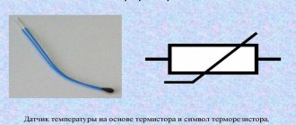
An example of nonlinear resistors is an ordinary light bulb, whose resistance in the off state is much lower than in the lighting mode. In photoresistors, the resistance changes under the influence of light, in thermistors - temperature, strain gauges - deformation of the resistor layer, magnetoresistors - magnetic field.
Resistor assembly
A resistor array is a combination of resistances that give the same values for all pins. These resistors are manufactured in single and double stacks. Resistor arrays are widely used in circuits such as ADC (Analog to Digital Converters) and DAC (Digital to Analog Converter) as pull-up resistors.
Types of resistors by purpose
Resistors according to their purpose are divided into two main types - general purpose and special. In turn, special resistances are divided as follows:
- High frequency.
Why are such resistors needed in electrical circuits: due to their low intrinsic capacitances and inductances, high-frequency resistors can be used in circuits in which the frequency reaches hundreds of megahertz; they act as ballast or termination loads in them. - High resistance.
The resistance value is in the range from several tens of MOhms to TOhm, the voltage value is small - up to 400 V. High-resistance elements operate in an unloaded state, so they do not need high power. Their dissipation power does not exceed 0.5 W. High-resistance resistors are used to limit current in dosimeters, night vision devices and other devices with low currents. - Precision and ultra-precision.
These devices have a high accuracy class: the permissible resistance value is 1% of the nominal value or less. For comparison: for conventional resistors, the permissible range is 5% or more. Precision devices are mainly used in high precision measuring instruments.
The principle of operation of a resistor in simple terms
All electronic devices consist of radio components, which are divided into two large types: active and passive.
Active ones amplify electrical signals. A weak signal at the input controls a strong one at the output. In this case, the gain is greater than unity.
The resistor is a passive type of part whose gain is less than unity.
In Soviet times, resistors were called resistances. These days these parts are called resistors. This was done because all parts used in electronics have resistance. To avoid confusion, active resistances are called resistors.
All conductors have resistance, which is considered harmful, since it leads to heating of the element through which the current flows. In addition, electrical power is lost. The value of the resistor is useful. It heats up and produces heat. Heating stoves and lamps used in everyday life operate on this principle.
Resistor noise and ways to reduce it
The intrinsic noise of resistive elements consists of thermal and current noise. Thermal noise caused by the movement of electrons in the conductive layer increases with increasing heating temperature of the part and the ambient temperature. When current flows, current noise is generated. Current noise, the value of which is significantly higher than thermal noise, is mainly characteristic of non-wire resistors.
Ways to deal with noise:
- The use in the circuit of types of resistors in which the noise is low due to manufacturing technology.
- Variable resistors are noisier than constant ones, so in the circuit they try to use elements with a variable resistance of a minimum value or not use them at all.
- Using retractors with more power than required by the technology.
- Forced cooling of the element by installing a nearby fan.
Resistor structure from the inside
The simplest resistor is a rheostat. A wire with high resistance is wound around the frame and connected to a power source. Based on this, we can conclude: the first requirement for this element is a high-resistance conductor. To produce this element use:
- wire;
- metal film, metal foil;
- composite material;
- semiconductor.
Metal foil made of high-resistivity material is wound onto the frame. If it is necessary to increase the resistance, it is cut into a track, thereby increasing the length and, accordingly, the resistance. A metal film resistor is produced by sputtering metal onto a base.
Graphite with organic or inorganic additives is used as a composite material. The resistor may consist entirely of such material or of a track on which this material is applied.
With the beginning of the production of microcircuits, new resistors appeared, which are called integrated. Manufacturing is done at the molecular level. A thin layer of high-resistivity metal is sprayed onto a highly doped semiconductor, which acts as a resistor.
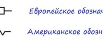
Designation of resistors in the diagram
| Fixed resistor without specified power dissipation rating |
| Fixed resistor with rated power dissipation 0.05 W |
| Fixed resistor with rated power dissipation of 0.125 W |
| Fixed resistor with rated power dissipation of 0.25 W |
| Fixed resistor with rated power dissipation 0.5 W |
| Fixed resistor with rated power dissipation 1 W |
| Fixed resistor with rated power dissipation of 2 W |
| Fixed resistor with rated power dissipation 5 W |
Designation of variable, trimmer and nonlinear resistors in the diagrams:
| Designation according to GOST 2.728-74 | Description |
| Variable resistor (rheostat). | |
| A variable resistor connected as a rheostat (the slider is connected to one of the outer terminals). | |
| Trimmer resistor. | |
| A trimmer resistor connected as a rheostat (the slider is connected to one of the outer terminals). | |
| Varistor (resistance depends on applied voltage). | |
| Thermistor (resistance depends on temperature). | |
| Photoresistor (resistance depends on illumination). |
The symbol for a resistor in the diagram is a rectangle measuring 4x10 mm. On the diagrams, the value of the constant resistance of less than a kOhm is indicated next to its symbol with a number without a unit of measurement. With a rating from one kOhm to 999 kOhm, the letter “K” is placed next to the number, from one MOhm – the letter “M”. The characteristics of resistors are indicated on their surfaces, for which an alphanumeric code or a group of colored stripes is used.
Examples of alphanumeric notation for resistance expressed as an integer:
- 25 Ohm – 25 R;
- 25 kOhm – 25 K;
- 25 MOhm – 25 M.
If a decimal fraction is used to express the value of resistance, then the order of numbers and letters will be different, for example:
- 0.25 Ohm – R 25;
- 0.25 kOhm – K 25;
- 0.25 MOhm – M 25.
If the resistance is expressed as a number other than zero and with a decimal fraction, then the letter in the designation plays the role of a comma, for example:
- 2.5 Ohm – 2R5;
- 2.5 kOhm – 2K5;
- 2.5 MOhm – 2M5.
Manufacturers, due to imperfect production technology, are not able to 100% guarantee that the declared resistance value corresponds to the actual one. The permissible error is indicated in % and is indicated after the nominal value, for example ±5%, ±10%, ±20%. The accuracy class can be determined by a letter, depending on the manufacturer - Russian or Latin.
| Permissible error, ±% | 20 | 10 | 5 | 2 | 1 | 0,5 | 0,2 | 0,1 |
| Letter | ||||||||
| Russian | IN | WITH | AND | L | R | D | U | AND |
| Latin | M | K | J | G | F | D | C | B |
Marking
The size of the resistive element is directly related to its dissipation power; the higher it is, the larger the dimensions of the part. If it is easy to indicate any numerical value on the diagrams, then marking products can be difficult. The miniaturization trend in electronics production necessitates the use of ever smaller elements, which increases the complexity of both applying information to the case and reading it.
To facilitate the identification of resistors, alphanumeric markings are used in Russian industry. Resistance is designated as follows: the numbers indicate the value, and the letter is placed either behind the numbers (in the case of decimal values) or in front of them (for hundreds). If the value is less than 999 Ohms, then the number is written without a letter (or the letters R or E may appear). If the value is indicated in kOhm, then the letter K is placed after the number, and the letter M corresponds to the value in MOhm.
American resistor values are indicated by three numbers. The first two of them involve the denomination, the third - the number of zeros (tens) added to the value.
In the robotic production of electronic components, the printed symbols often end up on the side of the part that faces the board, making the information impossible to read.
Color coding of wirewound resistors
For resistors, color coding is used, which is applied in 3, 4, 5, 6 color rings. If the rings are shifted to one of the terminals, then the ring closest to the terminal is considered to be the first (where decoding of the code begins). If the rings are located approximately evenly, then it should be remembered that the first ring is not made silver or golden. In some models, code reading begins on the side where the paired rings are located; a separate ring is usually located at the end of the cipher.
Color ring decoding table
| Color | Number | Decimal multiplier | Accuracy class, % | Temperature coefficient of resistance | % failure |
| Black | 0 | 1*100 | — | — | — |
| Brown | 1 | 1*101 | 1 | 100 | 1 |
| Red | 2 | 1*102 | 2 | 50 | 0,1 |
| Orange | 3 | 1*103 | — | 15 | 0,01 |
| Yellow | 4 | 1*104 | — | 25 | 0,001 |
| Green | 5 | 1*105 | 0,5 | — | — |
| Blue | 6 | 1*106 | 0,25 | 10 | — |
| Violet | 7 | 1*107 | 0,1 | 5 | — |
| Grey | 8 | 1*108 | 0,05 | — | — |
| White | 9 | 1*109 | — | 1 | — |
| Silver | — | 1*10-2 | 10 | — | — |
| Gold | — | 1*10-1 | 5 | — | — |
In a four-band code, the first two stripes indicate two denomination signs, the third strip is the decimal factor, that is, this is the power to which the number denoting the denomination must be raised. The fourth bar indicates the accuracy class of the element. In a five-line cipher, the third line represents the denomination sign, the fourth the decimal factor, and the fifth the accuracy class. If a sixth band is present, it indicates the temperature coefficient. If this ring is one and a half times wider than the others, then it characterizes the percentage of failures.
Convenient online programs will help you decipher the codes of wirewound resistors. Moreover, it makes sense to turn to them when deciphering the SMD resistor code, since there are several marking options that will be very difficult to figure out on your own.
Types of connection of resistors in an electrical circuit
The effective operation of electrical circuit elements with a resistor depends on the correct choice of not only the resistance itself, but also the method of its connection in the circuit, which can be series, parallel or mixed.
Serial connection
Series connection of resistors
In such a circuit, each subsequent resistor is connected to the previous one, forming an unbranched circuit. The current in series-connected circuits is the same, but the voltage is different. The total resistance of several serially located "rezyuks" is determined very simply - by summing their values.
Formula: Rtot. = R1 + R2 +…+ Rn
The more elements in a series circuit, the greater the total resistance.
Parallel connection
Parallel connection of resistors
In a parallel connection, resistors are connected to each other by inputs and outputs. The voltage across these elements is the same, and the current is distributed between them. The more branches are formed, the more options for current flow and the lower the overall resistance.
Formula: Rtot. = 1/R1 + 1/R2 +…+ 1/Rn
Mixed compound
Mixed connection of resistors
With this method, options for connecting elements are combined. The resistance of each section with a certain type of connection is calculated according to the above rules.
Connecting several resistors in one circuit
If you don’t have the resistance of the required value on hand, you can get it by correctly connecting several resistors. So, if you need a resistance of 100 kOhm, and there are two resistive parts of 50 kOhm each, then you can connect them in series and get the desired result. A resistance of 100 kOhm can be obtained by parallel connection of 200 kOhm elements.
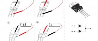
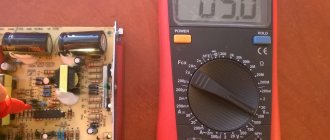
How to test a resistor
Almost any multimeter is suitable for testing a resistor. With a fixed resistor, only two things can happen:
- The resistor breaks - its resistance tends to infinity;
- Strong change in resistance.
In the electrical circuit, it is easy to notice a burnt resistor - in this case, it should have been tested using a multimeter. It should be noted that a resistor break can occur without changing its appearance (without “burning”).
The resistor testing process is as follows:
- Determine resistance by digital or color markings;
- Set the multimeter to resistance measurement mode based on the resistor value;
- Check that the resistance matches that indicated on the housing.
If the resistor resistance is within acceptable limits (for carbon domestic resistors C1-4, permissible deviations from the nominal value can reach ±10%), then the resistor is in good condition. Otherwise, it needs to be replaced.
The process of testing fixed resistors using a digital multimeter is demonstrated in the video below.
Testing variable resistors is a little more complicated. It is necessary to check the quality of contact of the brush with the conductive element. In some cases, a faulty variable resistor can be repaired.