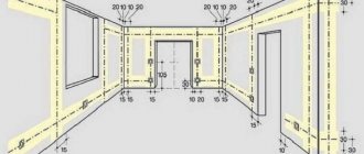
Installation of a shield for a suburban building
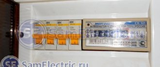
- Using self-tapping screws, we install the Din rails on which all the equipment will be attached. They must be 35 mm in size.
- We begin to install the equipment according to a pre-made diagram and calculations, install automatic machines, RCDs and two separate buses to which ground and zero are connected, and install a metering device.
- We connect the phase wires and connect the machines using a special bus. According to the general rules for connecting such devices, the input should be at the top and the output at the bottom.
- We install protective covers and sign all machines for convenience.
- Then we connect them with a special comb or make jumpers from wire. If you are going to use a comb, then remember that the cross-section of its core must be at least 10 mm/sq.
- We run wires from consumers into the machines.
Learn from this video how to properly assemble a 220 V electrical panel in a private house:
From the following video you will learn how to make a 380 V three-phase electrical panel in a private house:
After you have assembled the shield, without closing it, turn it on for a few hours, and then check the temperature of all elements. Do not allow the insulation to melt, otherwise a short circuit will occur in the future.
With a careful sequential approach and compliance with electrical safety rules, anyone can assemble an ASU on their own, although they will have to tinker. Having completed the installation, all you have to do is wait for representatives of the electrical network company, who will check your circuit and arrange the connection.
Single-branch rope slings 1SK are used at temperatures up to 100°C. They are considered reliable and durable slings that are resistant to dynamic loads. The best way to choose and order a 1SK sling is at bsts.ru
Simplified diagram of an apartment panel
Scheme No. 1
This scheme is suitable for small one or two room apartments. Where the total length of all wires and cables does not exceed 300-400m.
There is a load switch at the input, not a circuit breaker. If you already have protection installed on the floor switchboard, after or before the meter (check this before assembling this circuit), then it is not necessary to install a machine at the input. The better the load switch from the machine can be found in the article Modular load switch or incoming machine.
The rated current of the input device for apartments with electric stoves and single-phase load should be from 40A and above. Below are group cables feeding certain groups, indicating the cable brand and its cross-section depending on the load. Outgoing lighting circuits made with a 1.5mm2 cable are protected by a 10A circuit breaker, socket groups with a cross section of 2.5mm2 are protected by 16A.
The bathroom is connected to the differential machine, i.e. sockets, lighting and all consumers in the bathroom are combined into one group. Moreover, the leakage current on the diff is selected to be 10 mA.
Some electricians set it to 30mA, citing possible false alarms. There is no specific prohibition in the rules; it stipulates that this protection should not exceed 30 mA. Why it is still better to set it to 10mA can be understood by familiarizing yourself with how a current of a certain magnitude affects your body:
True, in order to purchase 10mA differential automatics in stores, you will most likely have to place an order. Basically, devices with a leakage current of 30 mA predominate on the free market.
The hob and oven are powered in separate groups, implying that these are two different consumers. If you have an electric stove, that is, when the hob and oven are combined, you need to change the power cable and circuit breaker:
Scheme No. 2
If you are concerned about power outages and want to protect your equipment from power surges, then you can slightly increase the cost of the circuit by adding a voltage relay to the input. Here is a schematic representation of a relay of the UZM-51M brand, as the easiest to connect (input-phase + zero and output-phase + zero).
Scheme No. 3
The advantages of these schemes:
- inexpensive
- the best option for small apartments
- easy to install and connect
The big disadvantage of the circuit is that if there is a current leak in lines other than the bathroom, the protection will not work.
This circuit can be improved by placing an RCD at the input. Before doing this, make sure that a circuit breaker is installed in the floor panel where your meter is located, since it is prohibited to install an RCD without a circuit breaker. If there is already an RCD or automatic circuit breaker there, then it makes no sense to duplicate the protection. The circuit with the RCD at the input will be like this:
Scheme No. 4
One caveat - if your total cable consumption in the wiring of an apartment is 400 m or more, then false alarms of the input RCD are possible due to total current leaks. Here it is already advisable to apply the RCD to separate groups, removing the introductory one from the apartment panel diagram.
Protection against electric shock
To protect a person from the action of current in case of unexpected contact with a bare conductor and the body of an electrical appliance, a residual current device (RCD) is installed in the panel. If you simultaneously touch a phase wire and a grounded conductive body, the power supply is turned off. For an apartment, the operating current is selected at 30 mA. It is not dangerous to humans, although it causes unpleasant pain. It does not work due to a short circuit. Therefore, an automatic circuit breaker must be connected along with it in the electrical circuit. If you use a differential circuit breaker, it performs the function of both devices, triggering not only a short circuit, but also a current leak.
Wet rooms and powerful consumers are supplied with separate RCDs or automatic circuit breakers. In a humid environment in wooden structures, even a current of 30 mA can cause a fire. In such areas, wiring requires special attention and protection.
Notes and additions
- The color identification of conductors in this switchboard is made in accordance with the requirements of GOST R 50462–92, which was in force from January 1, 1994 to December 31, 2010. Currently, the requirements of GOST 33542–2015 should be followed.
- Type A UDT operates with sinusoidal and pulsating direct currents.
- Input block is a functional block of the apartment panel through which electricity is supplied to the switchboard, containing switching and protective devices, and also includes a part of the switchboard volume intended for placing, fastening and connecting input conductors to the internal electrical circuits of the switchboard.
- Distribution block is a functional block of an apartment panel that contains protective devices for final electrical circuits and includes a part of the switchboard volume intended for placing, fastening and connecting the conductors of these electrical circuits to the internal electrical circuits of the switchboard.
- This control panel takes into account “Changes 1”, which were adopted in March 2017 by the International Electrotechnical Commission to the IEC 60364-4-41:2005 standard (on the basis of which the national standard GOST R 50571.3-2009 was created and is currently in force). Let me remind you that these “Changes 1” require mandatory additional protection by means of UDTs with a rated differential current not exceeding 30 mA for all final electrical lighting circuits, the lamps of which are located in domestic premises. This requirement is logical, since in residential premises lamps are often installed within the reach of a hand. Moreover, the lamps are used by ordinary people.
Sequence of correct installation of an electrical panel
To ensure that the electrical panel in your home is installed correctly, you should use only high-quality electrical products, as well as consumables. Only after installation is completed, operating voltage is supplied to the panel.
The correct assembly of a three-phase electrical panel has the following sequence:
Installation of an introductory machine. The device rating must cover the maximum power consumption. Since 3 phases will be brought into the house, the voltage between them will be 380 V, it is necessary to install a three-pole circuit breaker. To save money, it is not recommended to install 3 single-pole circuit breakers and connect them with a special strip. The input machine is installed in the upper left corner of the shield and is marked accordingly. After the introductory machine, it is necessary to install an RCD. The rating of the device must correspond to the rating of the input switch
You should also pay attention to the cut-off current - the lower this indicator, the faster the RCD will turn off the network. There are differential circuit breakers that include protective functions against short circuits and shutdown of the network when a leakage current occurs (RCD and standard switch)
It is easier to use such a product, but its cost is quite high. To the right of the RCD, at a short distance, a zero bus is mounted. Modern busbars provide a plastic dielectric between the copper strip and the shield body. This is done so that if the zero burns out and a phase gets on it, the electrical panel does not end up under life-threatening voltage. Measuring instruments and voltage relays can also be placed on the strip with the input circuit breaker, RCD and zero bus. If you install a voltmeter and an ammeter in a three-phase network, then you must select products that display both linear and phase loads. And also capable of showing data on each phase separately. The lower DIN rail contains automatic switches for power and lighting lines. In order not to get confused and not constantly look at the rating of the machines, lighting line products should be located at a short distance from the power switches.
After assembling the shield, you can mount it to the wall and connect the wires from consumers to the machines. An example of an electrical panel diagram, the number of machines can vary depending on the wishes of the owner.
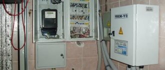
If the electricity metering panel with a voltage of 380 V is not located on the street, then it is first installed in front of the input machine. But installing a device to monitor electricity consumption in the house is inconvenient, so inspectors (to save time and the absence of owners) must take readings on the street.
Nuances of commissioning work
After the panel device is installed, it is necessary to turn off all devices with which it is equipped. Next steps:
- load all sockets;
- Apply voltage, check its presence at the input, correct phase and zero;
- check the RCD and automatic circuit breakers one by one;
- estimate the voltage at the input and output of the machines;
- check the behavior of the shield when connecting high power equipment;
- check sockets and switches.
The electrical panel requires periodic inspections. Once a month it should be opened, the contacts tightened, and the quality of the RCD work assessed. If the shield is installed correctly, it will last quite a long time.
Drawing up and approval of the project
The internal electrical wiring project for a private house consists of:
- calculation of power, input devices and required wire cross-section;
- calculation of grounding and lightning protection systems;
- electrical wiring diagrams;
- layout plan for cable lines and power equipment in the building;
- estimates for consumables.
Such a full-fledged project of in-house wiring is done only under a contract with a specialized company with a license. If it then has to be approved by the electrical energy supplier, then the drawings and calculations made independently will not be accepted for consideration.
You can only make an electrical and/or wiring diagram yourself, which will facilitate the work when installing electrical wiring yourself. They schematically indicate protection devices and wire lines to simplify the preparation of estimates and assembly of the entire system.
House wiring diagram
Phase selection
One of the most important considerations in design and wiring diagrams is the type of input voltage. There is no need to analyze specifically here, such as, for example, the numerous pros and cons of a pile foundation. It can be single-phase or three-phase, 220 or 380 Volts. When choosing, you must proceed from the available capabilities of the supply transformer (which can be provided by power engineers) and current-consuming electrical equipment.
In other situations, when a private house does not exceed 100 square meters in area and does not have electric water heaters, you can get by with ordinary single-phase 220 V. The requirements for three-phase electrical wiring are higher. It costs more, but is not always needed. It should be taken into account that 380 V on three phases may be required in the future. And then the approvals will have to start all over again. Here everything needs to be weighed and foreseen in advance.
How to calculate power consumption when wiring
To calculate the total power consumption and the electrical wiring required for this at home, it is necessary to sum up the kilowatts of all household and lighting fixtures in the home. These parameters are available in equipment data sheets and in special tables. Plus, starting loads and 20% in reserve are added here.
The most energy-intensive in a cottage are instantaneous water heaters (about 4–5 kW), electric stoves with ovens (up to 3 kW), electric heaters (1.5–3 kW), vacuum cleaners (about 1.5 kW) and washing machines (about 2–3 kW). 2.5 kW). Ventilation in a private house also consumes a lot if it is made with supply and exhaust and heated air without a recuperator.
Average power consumption of household appliances
Light, especially if it is LED, requires relatively little (up to 0.5 kW). Televisions, computers and other household appliances currently consume approximately the same amount. But all this must be taken into account and added up in order to calculate the total power of the cottage. It is needed to obtain specifications and calculate the cross-section of electrical wiring.
How to calculate the carrying capacity of electrical wiring
Consumer groups
To ensure that the load in the intra-house network is distributed evenly, consumers are divided into several groups in the wiring diagram. For example, one goes to the street lighting of the local area, the second to the outbuildings, the third to the lighting fixtures in the cottage and the fourth to the sockets in it. If the house is large, then such a breakdown can be made by floors and rooms.
Main consumption groups
Each individual line has its own automatic circuit breakers and RCDs (residual current devices). This increases the safety of operation of the home electrical network and simplifies the search for problem points in the system when the protection is triggered. The electrical wiring diagram must indicate all protective devices and the current consumption on the circuit that is powered from each of them.
The group RCD and the wire cross-section behind it are selected so as to correspond to the consumption of a specific group. It is recommended to allocate your own power line for powerful equipment, but for other equipment the number of consumers should not be higher than 5–6 sockets. It is better to include more of them in the project, but with less risk of core burnout due to long-term overloads.
Load distribution algorithm across three phases
As already mentioned, it is necessary to collect the entire single-phase load and distribute it evenly between the phases. Moreover, the trick is to select everything so that powerful devices connected to one phase do not cause an overload shutdown. This is possible if the total power of the operating devices is no more than the nominal value, or if these devices do not operate simultaneously.
A 380 V apartment panel may not be very large
General principles of load grouping for automatic machines
The most reliable and easy-to-maintain scheme is when for each group of consumers or powerful device there is a separate machine, and together with it an RCD. But such a scheme, firstly, is expensive, and secondly, it simply requires a huge cabinet, which is also not cheap. Therefore, they try to connect several lines to one machine, but they must be combined following a certain logic. Otherwise, it will be very difficult to figure out what’s what when the machine is triggered. You should adhere to the following rules:
- Connect sockets and lighting in one room through different machines. In this case, if there are problems in one of the groups, the room will not be completely de-energized.
- “Wet” rooms - bath, kitchen, bathhouse - should not be grouped with “dry” ones. Firstly, in rooms with increased danger, machines should have different parameters, and secondly, it is in wet rooms that problems usually arise.
- Street lighting and street sockets generally should be separate - on separate machines. Outbuildings can be connected to them.
- The power supply for the gate drive and security lighting are also separate machines.
- Separate power lines and separate circuit breakers and RCDs are installed on both powerful household appliances (electric stoves and electric ovens) and those that use water. As a last resort, you can combine, say, a washing machine and a dishwasher. You can also combine instantaneous and storage water heaters into one group, but on the condition that they will not turn on at the same time, since they are highly likely to trigger an overload shutdown. Moreover, they can be connected to one machine only if they are installed in the same room, otherwise you will not understand anything if damaged.
To make it easier to form groups, make a list of lines and the load on them. The room, line name and power of the connected load must be indicated. Looking at this table, following the rules described above, you assemble groups. At the same time, you must also ensure that the load is distributed more or less evenly.
Checking groups
After you have sketched out the groups on paper, check them. Sit down and think about what will happen if each of the machines works, how catastrophic the consequences will be for each room.
You can assemble a 380 V switchboard for a private home with your own hands, but you must first figure out how to distribute the load
For example, if in a two-story cottage you connect all the sockets of the first floor and the lighting of the second to one machine, and the lighting of the first, the sockets of the second to another, and the equipment to the third, then when any of the machines is triggered the situation will be terrible.
This is how we lose situations with each machine being turned off. It is advisable that there be either working sockets in the room or that they be in the adjacent one. Then, if necessary, it will be possible to connect equipment and lighting.
https://youtube.com/watch?v=jaB-iPXHZFs
Distribution board with single-phase load
The simplest wiring diagram for a house or cottage will be with a single-phase load. It is enough to analyze the installed load and distribute it equally among the phases. In this case, there will be no phase imbalance in the network.
The permitted power for a private house at a voltage of 380 V is 15 kW, in this case a 15 kW distribution board diagram is proposed in the design documentation.
However, these are only recommendations, and the owner distributes the connection to consumers at his own discretion. A five-core cable is laid from the input box to the distribution board.
In addition to the phase wires, a neutral and ground wire are installed. The panel is installed using colored wires with a cross-section of at least 4 mm. According to the PEU, the neutral wire must be blue or cyan, and the ground wire must be yellow-green.
Phase wires can have any other colors. A 380 V switchboard in a private house when connecting a single-phase load turns out to be quite simple, and the switchboard is small in size. In which single-phase circuit breakers and RCD protection devices are mounted.
A distributed load is connected to the machines. It is not recommended to connect only lighting to one machine or only sockets. The load must be distributed evenly to avoid phase imbalance. A Din-rail is mounted in the panel body, on which the machines are mounted. The neutral and ground bus are mounted below. Such electrical distribution boards are installed for a small country house if three-phase voltage is supplied to the country house.
In this case, the load is connected to the automatic circuit breakers according to the following diagram:
- The boiler and pumps are connected via a machine to the first phase;
- Sockets and lights in the kitchen to the second;
- Lights and sockets in the hall to the third.
In this case, the load will be distributed relatively evenly across the phases. Such assemblies are very convenient in terms of triggering the machine. When an emergency shutdown occurs, it is immediately clear where the malfunction occurred.
Features of a three-phase network
The first and most important thing to understand is that three-phase and single-phase equipment can be connected to a 380 V network. The difference is that three-phase is connected immediately to three phases and a neutral, and single-phase is connected to one of the phases and neutral. This connection - to one of the phases and the neutral - gives 220 V.
Do not think that the presence of three-phase equipment is mandatory. Not at all. Simply, when connecting powerful equipment to three phases, its load is distributed equally between all three phases. This means that you can use wires of a smaller cross-section and machines of lower ratings (but the wires are four/five wire, and the machine is three or four pole).
Example of a 380 V network with and without three-phase load
The peculiarity of the 380 V power supply is that there are three phases and the power allocated to you is divided equally into all three phases. If you are allocated 18 kW, each phase should have 6 kW. In this case, a three-pole or four-pole circuit breaker is installed, which will turn off the power supply completely if the load on one of the phases is exceeded. The machine has some time delay, but it is very small, so you will have to carefully calculate the distribution of the load across the phases, otherwise the light will constantly turn off due to overloads. This is the so-called “phase imbalance”, which interferes with normal life.
Optimal diagram of a 380V electricity metering board for a private house 15 kW
It differs from the previous one in the presence of a selective Safety Shutdown Device (number 6), it works immediately for all consumers in the house, it is also called fire protection. The installation of an RCD at the entrance to the house is recommended by the Electrical Installation Rules - PUE.
Metering board diagram for a private house with selective RCD, For TT grounding system
This is the most balanced scheme that can be implemented for a remote electrical metering panel at home, simple and reliable. It is suitable for everyone, and this is what I recommend collecting.
To improve it, in order to enhance the protection of the electrical network and electrical appliances at home, you can add a surge protection device (SPD).
Single-pole circuit breakers + 4-pole RCDs + cross modules
Advantages:
ability to make changes by phase
visual grouping
reasonable price
medium-sized shield (72-102 modules)
presence of zero tires
In fact, here we get a kind of mixed scheme, with the advantages and disadvantages of all the previous ones. Conventionally, several group lines will be hard-wired to single-pole circuit breakers, without the possibility of making any changes in the future regarding load distribution.
But on the other hand, you enable some other group, for example “sockets” or “lighting”, in such a way that through cross-modules you can later change the loading of one or another phase.
All this makes the three-phase shield slightly smaller, plus much cheaper. But it has great advantages in maintainability and in terms of making changes to the existing power supply circuit.
Types of inclusions and their features
Depending on the method of switching the windings of current transformers, three-phase meters installed in electrical networks are connected according to the following schemes:
- direct connection;
- indirect inclusion;
- semi-indirect connection.
Direct inclusion is called direct inclusion, and to understand the differences between the second and third types, it is necessary to take into account the scope of their application. Purely indirect connection is the open installation of current transformers (CTs) on high-voltage power cables of a three-phase line (6-10 kV). This method is found only at power substations and at large industrial enterprises with their own power distribution networks. In domestic conditions, this type of connection of transformers is not used.
Installation and connection of elements
All modern automatic devices and RCDs have a unified mounting for a standard mounting rail (DIN rail). On the back they have a plastic stop that snaps onto the bar. Place the device on the rail, hooking it with the recess on the back wall, and press the lower part with your finger. Once clicked, the item is installed. All that remains is to connect it. They do it according to the scheme. The corresponding wires are inserted into the terminals and the contact is pressed with a screwdriver, tightening the screw. There is no need to tighten it too much - you can squeeze the wire.
They operate with the power off, all switches are turned to the “off” position. Try not to handle wires with both hands. Having connected several elements, turn on the power (input switch), then turn on the installed elements one by one, checking them for the absence of a short circuit (short circuit).
Connecting the input machine and RCD
The phase from the input is supplied to the input circuit breaker, from its output it goes to the corresponding input of the RCD (place a jumper with a copper wire of the selected cross-section). In some circuits, the neutral wire from the water is supplied directly to the corresponding input of the RCD, and from its output it goes to the bus. The phase wire from the output of the protective device is connected to the connecting comb of the machines.
In modern circuits, the input circuit breaker is installed with two poles: it must simultaneously disconnect both wires (phase and neutral) in order to completely de-energize the network in the event of a malfunction: this is safer and these are the latest electrical safety requirements. Then the circuit diagram for switching on the RCD looks like in the photo below.
When using a two-pole input circuit breaker
To learn how to install an RCD on a DIN rail, watch the video.
In any circuit, the protective grounding wire is connected to its own bus, where similar conductors from electrical appliances are connected
Grounding is a sign of a secure network and doing so is vital. Literally
To learn how to properly connect an RCD, watch the video tutorial.
When assembling the panel yourself, please note that the input machine and the meter will be sealed by the energy supply organization. If the meter has a special screw onto which a seal is attached, then the input machine does not have such devices. If it is not possible to seal it, you will either be denied entry or the entire panel will be sealed. Therefore, inside the common panel, a box is placed in one or two places (depending on the size and type of machine), and the input machine is mounted in it. This box is sealed upon acceptance.
Individual automatic machines are installed on the rails exactly like an RCD: they are pressed against the rail until it clicks. Depending on the type of machine (one or two poles - wires), the corresponding wires are connected to them. What types of circuit breakers are there, and how devices differ for single- and three-phase networks, see the video; the choice of circuit breaker rating is described here.
After the required number of devices are installed on the mounting rail, their inputs are connected. As they said earlier, this can be done with wire jumpers or a special connecting comb. See the photo for what the wire connections look like.
The machines in one group are connected by jumpers: the common phase arrives
There are two ways to make jumpers:
- Cut the conductors into the required sections, expose their edges and bend them in an arc. Insert two conductors into one terminal, then tighten.
- Take a long enough conductor and strip off 1-1.5 cm of insulation every 4-5 cm. Take pliers and bend the exposed conductors so that you get interconnected arcs. Insert these exposed areas into the appropriate sockets and tighten.
They do this, but electricians say the quality of the connection is poor. It is safer to use special tires. Under them on the case there are special connectors (narrow slots, closer to the front edge), into which bus contacts are inserted. These tires are sold by the meter and cut into pieces of the required length using ordinary wire cutters. Having inserted it and installed the supply conductor in the first of the machines, tighten the contacts on all connected devices. Watch the video on how to connect machines in a panel using a bus.
A phase wire is connected to the output of the machines, which goes to the load: to household appliances, to sockets, switches, etc. Actually, the assembly of the shield is completed.
Useful devices (devices)
Now let's look at the benefits that enhance electrical installation.
Stopper for DIN rail
A special limiter that is installed on a DIN rail and prevents axial displacement and skewing of devices mounted inside the switchboard on a DIN rail.
If a large number of modular devices are installed in a row, they usually move relative to the horizontal, which makes it difficult to install the external panel of the switchboard and disrupts its aesthetics.
The use of special limiters solves this problem and improves electrical installation standards. For more information on this, see the video at the bottom of this article.
Cross module
Cross-modules are very convenient to use when assembling distribution boards.
With their help, it is very convenient to make a branch of supply lines, especially when assembling 3-phase distribution boards, when it is necessary to distribute consumers into individual phases. The supply voltage is supplied to separate buses of the cross-module, and from them consumers are connected to the free terminals.
If you need to change something over time, you can simply make the switching inside the cross-module itself, without changing the installation inside the switchboard itself. It's very practical.
In the case of using several voltage control relays for maximum protection against voltage surges and surges in the supply network, it is also convenient to use a cross-module to connect them. I will tell you how to do this in the following materials, so subscribe to the newsletter and stay tuned for new materials on this and other topics!
Thus, the use of these four utilities when assembling distribution boards optimizes electrical installation and makes it better and more professional, provided, of course, that all rules and regulations are followed.
Watch the video
Distribution board - assembly benefits
I also recommend reading
How to order installation of a metering board
By contacting our company
- you will solve your problem of connecting electricity all at once in a complex: installation of poles for electricity; installation of an electrical panel; stretching SIP wires from the nearest power line to the pole and from the pole to the house
- you will feel our advantages - we work in an organized, clear, fast, professional manner
- we have advantages over our competitors, for example, we install metering panels at a distance from the support for ease of maintenance, we use a panel housing with a degree of protection of IP 65. There are some other distinctive features that we will not disclose...
- we provide all guarantees and a full package of documents for equipment and work
Call tel. seven days a week! We will answer all your questions.
List of sources
- www.asutpp.ru
- stroimontajbur.ru
- samelectrik.ru
- vse-elektrichestvo.ru
- ProFazu.ru
- mycountryhome.ru
- electrobox.su
- www.websor.ru
- electricremont.ru
How to assemble a 380V 15kW electricity metering panel
Three-phase 380V distribution boards are often used in private houses and much less often in apartments in new buildings. This allows you to reduce the cross-section of the cable approaching the house and correctly distribute the load. Often the allocated power per house is 15 kW. This is a very widespread practice in our country. With such allocated power, it is necessary to install an input circuit breaker with a rating of 25A. Also, 3-phase power supply allows you to connect electric stoves using a three-phase circuit. This allows you to reduce the rating of the machine, reduce the cable cross-section and reduce the current consumption per phase. For example, a hob with a power of 7 kW with a single-phase connection will consume a current of 31A, and with a 3-phase connection it will consume about 10A for each phase. Let's look below at typical and non-typical three-phase circuits with clear examples of real assembled electrical panels.
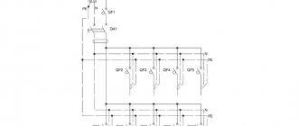
Three-phase distribution board diagram
A typical three-phase switchboard circuit consists of an input 3-phase circuit breaker and several group circuit breakers that protect only their outgoing single-phase lines. Here at the input there is a 3-pole circuit breaker with a rating of 25A-40A and with a characteristic higher than group single-phase circuit breakers (with characteristic C). This is necessary to try to maintain selectivity and avoid simultaneous operation of the input machine and the group one. Although in the event of a short circuit, both the input circuit breaker C25 and the group circuit breaker B16 will most likely work. With such a minimal difference in the ratings of circuit breakers, it is practically impossible to achieve selectivity.
In the circuit, we connect all neutral conductors to a common zero bus, all grounding conductors connect to a common ground bus, and phase conductors connect to circuit breakers. You can combine group circuit breakers by phase using wire jumpers, or better yet, using a special comb bus. Below is a typical three-phase 380V distribution board diagram. Maybe it will be useful for someone, I also inserted an electricity meter here. The TN-S grounding system is presented here. If you have a TN-C grounding system, then you definitely need to switch to a TN-CS grounding system, i.e. divide the incoming PEN conductor into independent zero working N and zero protective PE conductors. Read how to organize this correctly here.
Here is a clear example of connecting circuit breakers in a 3-phase electrical panel. You can see all photos of the assembly of this panel here: Assembly of three-phase electrical panels to order
If someone in the house, in addition to single-phase consumers, has a three-phase load, for example, an electric stove, then the following diagram of a three-phase distribution board should be useful to you. In the presented version, you can connect one 3-phase device and several single-phase ones.
If there is no place in the panel for an electricity meter or it is located in a different place, then here is a 380V panel diagram similar to the previous one, but without a meter. Here all phase conductors go directly to group circuit breakers.
If everything is clear with the previous three-phase distribution board diagrams, then we move on. Below I have posted a diagram for you, where there is also an RCD and a difavtomat. With their help, it is imperative to protect all groups of outlets. This is required by the PUE, and electrical safety should come first. Here the automatic device is only used for a washing machine, since if it is triggered, it will not be so difficult to find a fault. An RCD paired with a circuit breaker is installed on a group of kitchen sockets. You can find out why in pairs here. This is done to make troubleshooting easier, since many different electrical appliances will be included. If the machine works, it means there is a short circuit somewhere, or if you plugged in all the electrical appliances at the same time, then there is most likely an overload. If the RCD has tripped, then most likely there is a leak in some household appliance. Below is shown how to correctly connect an RCD and connect a difavtomat in a 380V panel.
Below is a real example of a three-phase switchboard with the connection of 2-pole and 4-pole RCDs.
Here's another diagram that might be useful to someone. It is built on one common (input) and several group RCDs.
The significance of the RCD in the brush
The RCD must be in the electrical panel. In addition, all outlet and power lines must be under RCD control. Principles for selecting RCDs:
For socket and power lines, an RCD is used, which has an infected response current of 30 mA. The rated operating current should be one step higher than that of the machine. In rooms with high humidity (hot tub, bathroom, washing machine, electric heated floor) there should be a 10 mA RCD in the outlet lines. In the diagram you can see that under one RCD it is permissible to install 2-4 lines with protective circuit breakers. It will be considered a group RCD
It is important to control - the operating current of the RCD must be equal to or greater than the total value of the ratings of the circuit breakers of the connected lines. Differentiated circuit breakers, which simultaneously perform the functions of an RCD and a circuit breaker, are not economically justified. Experts recommend connecting them separately
The use of difavtomats is justified only if there is not enough space in the electrical panel or protection of very important lines (warm floors in the bathroom).
After drawing up the diagram, it is better to show it to an experienced electrician, who will point out the pitfalls and make recommendations.
Need to know before assembly
The design includes mechanisms to protect people and wiring from overload or short circuit. as well as a counter. The cable goes from the power line to the house to the electrical panel and all the electrical groups of the house are routed from it.
In fact, the correct name for this device is an input distribution device (IDU). But according to the law, you must divide this unit into two and one of them will be input, and the second distribution.
The input device is usually installed on an electrical pole and is an electrical panel. in which there is a window made for the convenience of taking readings. There is an electricity meter inside. general RCD. input circuit breaker. arresters (they are rarely installed), elements for overvoltage protection. This design should be installed at a height of no more than 2 meters.
A cable is led from the input panel to the distribution installation. In private homes, the use of devices and protective shutdown devices is implied. To save space in the switchboard, differential devices are installed, which include a circuit breaker and an RCD.
The material from which the house is made, as well as where the shield itself is located, determines which of its options will be chosen.
Metal mounted electrical panels are used in wooden houses, and in stone houses, where it is drier, you can install a plastic box or a built-in panel.
The place for installing one single-phase circuit breaker is called a module. Each shield has a different number of modules. therefore, it is necessary to know what and how many devices will be installed in the panel.
The distribution block should be installed in a safe place, preferably in a separate nook.
Types of electrical panels
They differ in purpose, installation method, and material. Depending on the purpose of application, they are divided into:
- Main distribution board
(MSB). Serves for input and metering of energy into a large object (group). Receives energy from power lines, transformer stations or individual transformers. - Input switchgear
(ISU). It can perform similar functions of the main switchboard, or serve to further supply power to smaller objects. Measuring instruments that monitor current parameters are additionally installed in it. - Emergency commissioning of reserve
. This electrical panel automatically switches to backup power sources in the event of an emergency. The latter can be batteries and transformer substations. - Floor electrical panel
(SHB). Installed on the floors of buildings in specially designated areas. Carries the functions of further distribution of energy throughout the floor. - Apartment panel
(AS). Can be installed both inside apartments and on the floor. This electrical panel is responsible for powering residential areas, accounting for electricity consumption and protecting against the negative effects of electric current. - Lighting board
. It is used as a separate device to provide on/off functions for lighting devices. - Control and automation panels
. The panel for electrical circuit breakers is mainly used in electrical installations, power plants, and substations. Often control and automation functions are combined.
Mounted electrical panel
Manufactured in various depths (side wall width). They are designed for installation on a wall, a special device or a support. For the manufacture of a non-separable body, sheet steel 1 mm thick is used. The rigidity of the structure ensures reliable installation of the equipment. An apartment electrical panel can be made of plastic and have a collapsible body, consisting of a rear wall (mounting base) and a casing with a lid. They are connected to each other with special fasteners. When the cabinet height is up to 800 mm, the panels are equipped with one lock, above - two.
Built-in electrical panel
Designed for installation deep into the wall. Comprises:
- body made of steel 1 mm thick;
- steel mask with a door hung on it.
The housing has technological holes for wall mounting. Powder painting is carried out in an electrostatic field. To install internal equipment, mounting panels or modular systems are used. The electrical panel in an apartment of this type has the ability to change the door opening. The generally accepted wall installation depth is 120 mm. Internal protection degree IP31.
Floor electrical panel
Can serve as a main board for power input and distribution. A welded frame made of 2 mm thick steel provides rigidity to the structure. The filling consists of removable components and assemblies assembled linearly. It can have either one or two doors. The locking device can block the door in 4 places. At the installation site it is mounted on a special base. An electrical panel in a private house, located outdoors, is equipped with increased protection from the influence of the external environment, type IP55, 65.
Obtaining permission to connect to the local power grid
First, you need to undergo acceptance tests (technical inspection of the facility where the electrical installation was carried out). If the result is positive, you will be given a “Connection Certificate”, on the basis of which the owner of the electrical network must connect your residential property.
The rules for connecting to the network are described in RF PP 861 dated December 27, 2004 and its numerous editions (updated until 2015).
The energy supply company is obliged to connect to the power grid for facilities with a power of up to 15 kW, regardless of whether it has such a possibility. A connection with allocated power up to 15 kW, and a line length of no more than 500 meters, costs 550 rubles. For this money you will receive specifications for connection. After assembling the input distribution board, you need to contact the distribution network and call an inspector to seal it, then the electricians must connect your “box” to the electricity - the overhead power line support.
This issue is clearly discussed in the video:
So we looked at how electrical wiring in a house should be done with our own hands. We hope that the step-by-step instructions provided were clear and useful, and the video lessons helped to better understand the entire electrical installation process!
Also read:
- How to make grounding in a private house
- How to assemble an electrical panel with your own hands
- How to independently connect a site to electricity
05.11.2019
In addition to the shield components, you must:
How I installed the metering board on a support
- Input cable brand SIP-4 4x16 for connecting the shield to the line at the top of the support
- Usually the height of the support is 5-7 meters, but it is better to measure it in advance and take wires with a reserve
- Kit for running cables along supports. According to the specifications, the cable must be raised from the shield to the top of the support. This must be done in a corrugation or cable channel spaced 10 cm from the support. This is done so that if a local electrician suddenly wants to climb onto the support with the help of his claws, he would not damage the cable with them. I did this using M6 studs and pieces of din rail. PVC pipes and plumbing clamps
- Cable brand SIP-4 4x16 for creating a line from the ASU to the input into the house
- Set of piercing clamps and hangers for SIP
- A piece of metal corner 50x50 mm about 2 meters to create a re-grounding conductor, because I did not find a grounding loop on my support, and the shield must be grounded
Schematic diagrams of distribution boards
In this article you will find circuit diagrams of distribution and metering and distribution boards in the TN-CS and TN-S systems. There are more than a dozen schemes.
On schematic electrical diagrams, all devices mounted in the switchboard are indicated by symbols and signed with certain letters.
Letter designations in diagrams
- Circuit breakers and circuit breakers are designated Qx, AQx; QFx;
- Residual current devices (RCD): DQx, AQx;
- Differential circuit breakers: ADQx;
- Nx - zero buses (the bus number matches the number of the RCD connected to this bus);
- PEx - protective grounding buses;
(x is the serial number on the diagram).
- PEN – bus for connecting the neutral and protective conductor. If we divide (into PE and N) at the transformer, we get a TN-C system. If we divide it in another place, in a house or in panels on a floor or apartment, we get a TN-CS system;
- X1…..Xn – connection terminals.
Schematic electrical diagrams of distribution and lighting panels with comments
Scheme 1
Schematic electrical diagram of a lighting board for 12 circuit breakers, OSCHV 12. TN-CS grounding system.
Scheme 2
Similar to the previous scheme, but for 6 circuit breakers, OSCHV 6. TN-CS grounding system.
Scheme 3
Schematic electrical diagram of the metering and distribution board, ShchUR. The metering of the switchboard is determined by installing an electric meter in it. The power supply is single-phase, the grounding system is TN-S, that is, the PE and N conductors are led separately from the grounding of the transformer to the consumer.
Scheme 4
Scheme 5
Again, the TN-CS system. Shield for five groups.
Scheme 6
And again, the TN-CS system. Shield for ten groups. It is planned to install an introductory RCD (100 or 300 mA).
Scheme 7
Large schematic diagram of an electrical metering and distribution board (ASB). For example, for a private house (cottage). TN-CS system. The panel provides 5 groups for the home, three of them are protected by RCDs. Separate groups are allocated for the extension and bathhouse. Each with its own RCD or automatic circuit breaker.
ABB reversing switch switching diagram. ABB Mistral shield.
Next, UZM-51M is installed on each phase to protect against overvoltage and zero loss. After UZM-51M, we install a residual current device (RCD) with a rated current of 40A and a leakage current of 30 mA in the ABB shield for each phase, to protect against electric shock and fire.
Then two-pole circuit breakers with characteristic “B” are connected from the RCD. That is, our ABB shield turned out to be as follows: the first DIN rail is the introductory group, the second DIN rail is one phase, the third DIN rail is the second phase and the fourth DIN rail is the third phase. I think that this arrangement of automation in an ABB switchboard for 72 modules is quite intuitive.
The components of the ABB electrical panel, after they have been installed in the ABB panel on DIN rails, are fixed with special limiters. So that in the ABB shield the RCDs and circuit breakers do not crawl along the DIN rails in different directions and fit tightly to each other.
The upper contacts of the machines in the ABB panel are connected from the RCD with a special ABB bus (comb) at 63A. In our case, the ABB bus is double L1/L2(N), i.e. phase has its own bus (comb), and zero N has its own.
The ABB comb consists of two copper bars, the contacts of one of the bars are curved. I order ABB buses for 58 modules and, depending on the circuit, cut them to the required number of automatic devices or RCDs. The photo shows that the copper bars can be removed from the comb body and cut to the required length with ordinary metal scissors. I saw off the plastic body of the ABB comb with a small hacksaw.
After connecting the circuit breakers, UZM, RCD and automatic circuit breakers in the ABB panel, we take our frame with DIN rails and install it in the ABB panel, screwing the frame to the ABB panel body with self-tapping screws.
Next, I connect our terminal blocks for the PE protective conductor with PV3 (PUGV) wire with a cross-section of 10 sq. mm. yellow-green color.
Of course, I check whether the ABB Mistral 65 panel was assembled correctly. I connect a live cable to the input switch, etc. Our ABB Mistral 65 switchboard is three-phase, and the network in the apartment is single-phase, then I make a jumper to the other contacts of the ABB input switch, then I also connect the power supply of the ABB electrical panel to the reversing switch on the side of the backup electricity input (gasoline generator). Everything works, nothing is shorted anywhere, the voltage on the outgoing circuit breakers in the ABB Mistral 65 switchboard is normal.
I screw the top part of the ABB Mistral shield with the doors and close the voids in the ABB shield with plugs for plastrons. Special plugs are installed in the ABB shield, specifically for Mistral65 cabinets.
Then comes the “typographical” part of the work again. In the ABB shield, on its plastrons, I paste the symbols of the automation so that it is clear what our ABB shield includes, from which machines the consumers in the house are powered. The method for making automation markings in an ABB shield is the same as described above: double tape, a stationery knife, transparent tape and a metal ruler.
I carefully paste the designations of the machines, voltmeter, switches, UZM and RCD on the plastrons in the ABB Mistral shield.
That's all, the assembly of the ABB Mistral three-phase switchboard for a private house is complete. Then I complete the documentation for the ABB switchboard (an explanatory note with recommendations and diagrams, sales receipts from suppliers, invoices, passports and forms for machines, RCDs and other devices, I put a set of “lightning” and “voltage” stickers, I don’t stick them myself, because because the customer himself will decide where and whether they need to be glued at all).
I didn’t throw away the box from the ABB shield, so I pack the finished ABB shield in it. I paste warning papers on which side is best to open the ABB switchboard box, so that, for example, you don’t scratch the door with a knife.
I send the ABB panel by the transport company “Business Lines” to the customer of the electrical panel, scan the invoice and by e-mail, the customer can track the location of the electrical panel using the invoice number. I always insure the electrical panel, although there have been no unpleasant situations involving loss or damage to cargo.
A simple diagram for connecting the electrical panel of a private house 15 kW
The simplest budget option for assembling a metering board is presented below. Only the most necessary elements are used here:
2. Plastic box 3 modules, with eyes for seals
3. Three-pole Protective circuit breaker, characteristic C25 (for an allocated power of 15 kW this rating is needed)
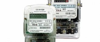
4. Electric energy meter (meter) 3-phase 380V
5. Distribution switching block, capable of connecting wires with a cross-section of up to 16 mm2.
Simple metering panel, TT grounding system
This option is often used as a temporary one, for example, to connect a change house during construction, as it has few means of protection.
For your house in which you plan to live permanently, even for a country house, I recommend using the following assembly:
Final installation
When all modular devices have been adjusted and tested, all that remains is to transfer them to the electrical panel housing. For safety, turn off the power. A niche in the wall is being prepared. The assembled devices are mounted on a DIN frame inside the housing.
The main and protective zero buses are mounted. When distributing wires among bundles, it is not recommended to allow them to intersect. The protective zero wires are attached to the PE bus. The connection sequence is observed as in the electrical panel diagram. The protective zero before commutation with the bus terminal is marked.
When all devices are connected, a check begins for compliance with the connection diagram. On the Internet you can see a photo of the assembled electrical panel.
When the adjustment is completed, do not rush to close the electrical panel. It should work for a couple of hours, and then it will become clear whether the assembly was carried out efficiently. Installing and connecting the shield is a labor-intensive process that requires certain knowledge and experience. You should start by studying the theoretical part and follow the step-by-step assembly instructions.
Some useful tips for assembling a shield
When assembling an electrical panel, it is necessary to use only high-quality and reliable electrical products
You should not pay attention to cheaper Chinese analogues; personal safety is much more important
To connect wires to machines, it is best to use special lugs for crimping. Of course, then you will have to purchase pliers with which crimping is performed, but their cost is not too high.
The use of insulating tape is no longer relevant; many electricians use exclusively heat-shrinkable tubing. This consumable is convenient and reliable, and it is not necessary to purchase a hair dryer; you can use an ordinary lighter.
For ease of use, all elements of the electrical cabinet must be marked. Only then will it be possible to quickly and easily turn off the voltage in a certain room. You can make notes on the body of the device or make small signs and attach them to the product with tape.