When connecting a cottage, correct distribution of the load across phases allows you to optimize the use of electricity, reduce the likelihood of overloads, breakdowns of electrical appliances due to inappropriate voltage, and even reduce meter readings. Let’s look at the possible nuances and look at several of the most popular schemes using illustrative examples.
Power supply for a cottage Source www.starling-k.ru
We assemble an electrical panel for a private house at 380 V 15 kW
Assembling an electrical panel for a private home with a voltage of 380 V and a power of up to 15 kW requires an appropriate approach and the presence of the following tools:
- pliers;
- flat and figured screwdrivers;
- crimping pliers;
- assembly knife with a set of replaceable blades.
All work begins with planning, and if the home owner prefers to contact an electrical company, then a project and preliminary diagram are drawn up before installation begins. You should also prepare the components of the shield and consumables (crimping lugs, heat shrink, DIN rail, dowels).
Rules for installing an electricity meter
There are rules, the distribution panel in which the input machine is mounted and the electricity meter must be installed on the wall of the house or a pole. This is necessary for regulatory authorities who check energy consumption.
Residents install the switchboard in a private house or cottage with their own hands. Connecting three-phase voltage allows you to reduce the load on the supply networks and significantly reduce the cross-section of the supply cable.
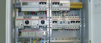
Since metering devices must be sealed, they are installed in a separate sealed box. The input three-phase distribution board is:
- Main machine;
- Surge protection equipment (SPD);
- Electricity meter.
Overvoltage pulses in the network occur for technological reasons when switching occurs at a substation. More often, overvoltage occurs when lightning strikes a power line.
Such discharges are characterized by a short exposure time, but a significant overvoltage. They are dangerous both for electrical networks and for equipment connected at this moment.
According to the terms of the PES, there must be a grounding loop next to the input. This must be taken into account when choosing the input location, and in no case should the neutral wire be combined with the ground loop.
When installing a 380 V switchboard in a private house, it is necessary to take into account the fact that the box with metering devices must be sealed. That is, access to the machines is limited.
What elements does an electrical panel consist of?
It is necessary to purchase the components of the electrical panel immediately, so as not to subsequently waste time and not travel to the electrical store several times a day. The power of the shield is determined, it is 15 kW, which means that the maximum power consumption will not exceed 15 kW/h.
Electrical panel of a private house, list of elements:
- Electric energy meter. The meter is the first element that must be installed in the panel. The best solution would be to purchase an electronic device designed to connect three phases. Such measuring instruments have high accuracy and a long service life. All information is displayed on a digital screen. Electronic meters can be programmed to operate in several tariffs.
- Electrical shield. Now in stores there are a large number of electrical panels of various sizes and designed for a certain number of elements. The price of the product varies depending on the presence of a DIN rail, a built-in lock, as well as an inspection window (especially for taking readings from the meter). You should pay attention to protection from dust and moisture, its level should be at least IP 54. Dimensions - 445 × 400 × 150, and a wall thickness of 1 mm.
- Input circuit breaker. You should purchase a three-pole machine, because the voltage supplied to the house will be 380 V, which means the presence of three phases.
- Residual current device (RCD). It is required to be installed, since it is a protective element when a dangerous potential appears on the body of an electrical device.
- Circuit breakers. The amperage should be selected based on the consumer load, which will be discussed below.
- Voltage relay. Protects household electrical appliances from power surges. Many users install a relay, but it is not a required element. Also now widely used is the surge protection device (SPD). For example, when lightning strikes an overhead power line, the voltage in the house will reach high limits, which will be destructive for all equipment. The SPD will turn off the network in time, but, like the voltage relay, it is not installed often.
- Measuring instruments. They are also an optional element of the electrical panel. Measuring instruments include ammeters and voltmeters, often combined into one product.
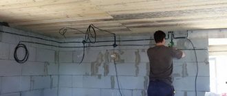
DIY wiring
Modern construction trends provide for hidden wiring. It can be laid in specially made grooves in the walls - grooves. After laying and securing the cables, they are covered with putty, comparing them with the surface of the rest of the wall. If the erected walls will then be lined with sheet materials - plasterboard, gypsum plasterboard, etc., then grooves are not needed. The cables are laid in the gap between the wall and the finish, but in this case - only in corrugated sleeves. The shell with laid cables is attached with clamps to the structural elements.
How should internal wiring be laid? In a private home, when installing it yourself, you must follow all the rules
When installing, you need to remember that the internal electrical wiring of a private house is done according to all the rules and recommendations. This is the only way to guarantee safety. The basic rules are:
- laying wiring only vertically and horizontally, no rounded corners or beveled routes;
- all connections must be made in installation junction boxes;
- horizontal transitions must be at a height of at least 2.5 meters, from which the cable runs down to the socket or switch.
A detailed route plan, similar to the one in the photo above, must be saved. It will come in handy during repairs or wiring upgrades. You will need to check with him if somewhere nearby you need to ditch or make a hole or hammer a nail. The main task is not to get caught in the cable.
Wire connection methods
A large percentage of electrical wiring problems come from poor wire connections. They can be done in several ways:
- Twisting. Only metals that are homogeneous or do not enter into a chemical reaction can combine in this way. It is strictly forbidden to twist copper and aluminum. In other cases, the length of bare conductors must be at least 40 mm. The two wires are connected to each other as tightly as possible, the turns are laid one next to the other. The connection is wrapped on top with electrical tape and/or packed with heat-shrink tubing. If you want the contact to be 100% and losses to be minimal, do not be too lazy to solder the twist. In general, according to modern standards, this type of wire connection is considered unreliable. The rules for installing electrical wiring in a private building prohibit making twists in the walls (bricking them up)
- Connection via terminal box with screw terminals. The housing is made of heat-resistant plastic and contains metal terminals that are tightened with screws. The conductor, stripped of insulation, is inserted into the socket and secured with a screw or a screwdriver. This type of connection is the most reliable. Connecting electrical wiring using terminal boxes is fast, convenient, reliable, and safe
- Connecting blocks with springs. In these devices, contact is provided by a spring. A bare conductor is inserted into the socket and clamped by a spring.
Still, the most reliable connection methods are welding and soldering. If it is possible to make the connection like this, you can assume that you will not have problems. At least with connections.
Installing electrical wiring in a house with your own hands requires careful fulfillment of all requirements. This is a guarantee of your privacy and the safety of your private property.
After the wires from the machine to the connection point of the socket or switch are laid, they are checked for integrity with a tester - the wires are connected to each other, checking the integrity of the conductors, and each individually to the ground - checking that the insulation is not damaged anywhere. If the cable is not damaged, proceed with the installation of the socket or switch. Once connected, everything is checked again with a tester. Then they can be started on the appropriate machine. Moreover, it is advisable to sign the machine immediately: it will be easier to navigate.
After finishing the electrical wiring throughout the house and checking everything yourself, they call electrical laboratory specialists. They check the condition of the conductors and insulation, measure grounding and zero, and based on the results they give you a test report (protocol). Without it you will not be given permission to put into operation.
Which circuit breakers to choose for the electrical panel
The main question that affects many users is: how to decide on slot machines? The rated current of the circuit breaker is calculated based on such parameters as the consumer’s load or its power.
For example. The rated power of simultaneously switched on electrical appliances and the lighting network will be 15 kW. There is a formula: P=U×I, where P is power, U is voltage, I is current. If P = 15000 W, then the current strength will be (rounded) 68 A. This means the sum of the rated values of the machines should not exceed 68 A. But it should be remembered that a three-phase network is connected to the switchboard, so the rated amperes must be divided by 3, which will give approximately 23 A. This means that the input circuit breaker should be set to 25 A.
For lighting networks, it uses 6.3 or 10 A automatic machines. These are generally accepted standards, which are convenient to resort to to save time. If you still have free time, then you can calculate the amperage of the machine for light using the above formula, only P will be equal to the sum of the powers of all lamps used in a separate or common lighting line.
The amperage of automatic circuit breakers for power circuits should not be less than 16 A. It is this nominal value that will allow you to use electrical appliances uninterruptedly for a long time. If you install a circuit breaker with a lower rated threshold, then turning on the household appliance will be perceived by the device as a short circuit on the line and the circuit breaker will turn off the voltage.
There may also be more powerful electrical appliances in the house: hobs, ovens, refrigerators. And if several sockets can be combined into one group, then such devices will require the installation of a separate circuit breaker with a value of at least 25 A. The power of a modern electrical panel can reach 7 kW and higher.
Calculation of energy consumers
Before distributing the load across phases, it is recommended to perform a preliminary calculation of consumers. This can be easily done by making a list of potential sources that will be assigned to a particular phase. For example, list the main household appliances and their power as stated by the manufacturer:
- Electric hob 6.5-7.5 kW.
- Washing machine 1.5-1.8 kW.
- Dishwasher 1.5-1.8 kW.
- Microwave oven 0.9-1.2 kW.
- Oven 2.0-2.6 kW.
- Vacuum cleaner 1.9-2.2 kW.
- Iron 1.9-2.2 kW.
How to properly divide energy consumers into several groups Source uk-parkovaya.ru
Important! If necessary, the list can be supplemented with other electrical appliances on the balance sheet.
Sequence of correct installation of an electrical panel
To ensure that the electrical panel in your home is installed correctly, you should use only high-quality electrical products, as well as consumables. Only after installation is completed, operating voltage is supplied to the panel.
The correct assembly of a three-phase electrical panel has the following sequence:
- Installation of an introductory machine. The device rating must cover the maximum power consumption. Since 3 phases will be brought into the house, the voltage between them will be 380 V, it is necessary to install a three-pole circuit breaker. To save money, it is not recommended to install 3 single-pole circuit breakers and connect them with a special strip. The input machine is installed in the upper left corner of the shield and is marked accordingly.
- After the introductory machine, it is necessary to install an RCD. The rating of the device must correspond to the rating of the input switch. You should also pay attention to the cut-off current - the lower this indicator, the faster the RCD will turn off the network. There are differential circuit breakers that include protective functions against short circuits and shutdown the network when a leakage current occurs (RCD and standard switch). It is easier to use such a product, but its cost is quite high.
- To the right of the RCD, at a short distance, a zero bus is mounted. Modern busbars provide a plastic dielectric between the copper strip and the shield body. This is done so that if the zero burns out and a phase gets on it, the electrical panel does not end up under life-threatening voltage.
- Measuring instruments and voltage relays can also be placed on the strip with the input circuit breaker, RCD and zero bus. If you install a voltmeter and an ammeter in a three-phase network, then you must select products that display both linear and phase loads. And also capable of showing data on each phase separately.
- The lower DIN rail contains automatic switches for power and lighting lines. In order not to get confused and not constantly look at the rating of the machines, lighting line products should be located at a short distance from the power switches.
Peculiarities
To reduce the likelihood of phase overload, the load is distributed evenly across phases. Failure to comply with this condition, as well as burnout of the “zero” conductor or its poor contact, will lead to a difference in voltage on the phase conductors, up or down.
Thus, converted single-phase power (220 V) will lead to malfunction of electrical consumers connected to it. This will happen due to the fact that some devices will receive an increased voltage (240-270 V), while others will receive a reduced voltage (160-200 V).
Important! If the load is unevenly distributed across phases, on meters that are not sensitive to distortions, there will be an increased consumption of electricity.
Some useful tips for assembling a shield
When assembling an electrical panel, it is necessary to use only high-quality and reliable electrical products. You should not pay attention to cheaper Chinese analogues; personal safety is much more important.
To connect wires to machines, it is best to use special lugs for crimping. Of course, then you will have to purchase pliers with which crimping is performed, but their cost is not too high.
The use of insulating tape is no longer relevant; many electricians use exclusively heat-shrinkable tubing. This consumable is convenient and reliable, and it is not necessary to purchase a hair dryer; you can use an ordinary lighter.
For ease of use, all elements of the electrical cabinet must be marked. Only then will it be possible to quickly and easily turn off the voltage in a certain room. You can make notes on the body of the device or make small signs and attach them to the product with tape.
Review of common design mistakes
Defects in the design or planning of work entail installation errors, and this threatens disruptions in the functioning of the electrical network. The result may be the failure of expensive equipment, and even worse, an electrical injury to one of the residents.
What mistakes should you avoid:
- use low-quality products without labeling and certification;
- make one-to-one calculations - any technical products and materials must be purchased with a reserve;
- include in the project the installation of conventional sockets for connecting hobs, boilers, heat guns;
- in wooden houses, plan to use closed wiring - more complex and subject to the list of requirements of the PUE;
- design switching of low-voltage and high-power power wires in one distribution box;
- plan to connect wires using twists that are dangerous for further maintenance and operation; the best option is ready-made terminals;
- make circuits from aluminum and copper wires, and also use aluminum wiring.
Some errors relate to incorrect calculations. For example, grooves under the cable with a closed installation method should be laid to a depth of 2-2.5 cm, no less.
It is incorrect to place distribution boxes at the bottom or at human height. Their place is under the ceiling, 20 cm from a suspended structure or concrete ceiling slab
You cannot connect the grounding of sockets using a cable, or ground them on cast iron sewer or steel gas pipes.
If you do not know how to properly install electrical wiring in your home, contact the design organization. Specialists will visit the site and draw up a wiring diagram based on specific installation conditions.
Electricity metering board diagram 380V for a private house 15 kW
technical specifications for connection from the electricity supply company (Mosenergo, Lenenergo, Sverdlovenergo, etc., depending on the region) . It is this document that contains the main characteristics of the electrical network available to you, including the requirements for the electricity metering panel.
In this article we will examine in detail the diagram of a typical metering panel , as well as its modifications, which require collecting the requirements of technical specifications.
In such cases, the standard network parameters for connecting a private home are:
– 3 phase
– Voltage: 380V
– Power allocated: 15 kW
– Input cable: SIP 4-core (3 phase conductors and PEN)
I would like to note that one of the main tasks of technical specifications is not only to ensure the safety of the electrical installation, but also to prevent the possibility of theft of electricity by consumers.
That is why all protection or switching devices in the electrical panel located before the electric meter must be protected from the possibility of illegal connection. Usually they are hidden in separate boxes, which are sealed when connected.
In addition, the technical specifications require that the metering board be placed in a place accessible for inspection - on the border of the site, on a lighting pole or fence.
Most often, such external panels are used exclusively for accounting, without additional capabilities, and provide only basic functions. The main distribution board (PDB), in this case, is installed inside the house, where all consumers are divided into groups, the load is distributed, the appropriate automatic protective equipment is installed, etc.
All the diagrams presented below will be designed for the two most popular grounding systems in private homes TT and TN-CS . Under each connection option there will be links to step-by-step assembly instructions, with detailed comments.
If you have not decided which grounding system to choose, the following information will help you:
TN-CS is the grounding system recommended by the rules. It has a number of disadvantages; it is worth using it if you are confident in the condition of the electrical networks suitable for the house, if they are new enough and regularly maintained.
TT is a relatively safer system. The main disadvantages include only the high costs of installing protective equipment and installing a ground loop, as well as regular maintenance. Which, for safe operation, must always be maintained by you in working condition.
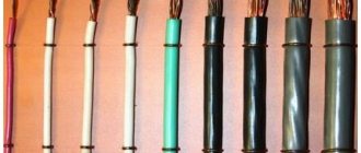
Recommendations for choosing wires
In houses made of brick, aerated concrete blocks, and cinder blocks, interior wall decoration is required, which means that a hidden method is used for laying wires.
To provide additional protection, and in case of repair to quickly replace the cable, it is placed in a corrugated sleeve of non-flammable polymer.
In houses made of timber or rounded logs, to preserve the retro style, they use an open method of laying wires, purchasing decorative products - twisted wiring, rollers, stylized switches and sockets
To select the correct wire cross-section, specialists perform calculations related to determining the load.
However, based on standard diagrams and many years of experience, qualified electricians adhere to the following parameters:
- lighting circuits – 3*1.5 mm² or 3*2 mm²;
- socket groups – 3*2.5 mm²;
- electric stove/oven – 3*4 mm²;
- air conditioning – 3*2.5 mm², for appliances more powerful than 5 kW – 3*4 mm²;
- heating boilers – 3*4 mm² or more (according to the manufacturer’s recommendations).
The optimal type of cable is three-core copper: VVGng, ShVVPng. It is impossible to use wires with a cross-section smaller than the specified one, as they will not match the load and will begin to melt, creating a dangerous situation.
A simple diagram for connecting the electrical panel of a private house 15 kW
The simplest budget option for assembling a metering board is presented below. Only the most necessary elements are used here:
2. Plastic box 3 modules, with eyes for seals
3. Three-pole Protective circuit breaker, characteristic C25 (for an allocated power of 15 kW this rating is needed)
4. Electric energy meter (meter) 3-phase 380V
5. Distribution switching block, capable of connecting wires with a cross-section of up to 16 mm2.
Scheme of a simple electrical metering panel for a private house 15 kW, TN-CS grounding system:
Simple metering panel, TT grounding system
This option is often used as a temporary one, for example, to connect a change house during construction, as it has few means of protection.
For your house in which you plan to live permanently, even for a country house, I recommend using the following assembly:
Electrician's recommendations
You should adhere to the basic rules when working:
- horizontal transitions from the junction box to the sockets or switch are laid at a height of 2.5 m;
- the insertion of veins is carried out only vertically or horizontally;
- connection points should only be located in mounting boxes;
- for underground cable laying, you need to use only a single piece with a strong armor tape;
- The biggest mistake is installing the switch in the zero gap;
- It is forbidden to install electrical wires near a wooden surface, but if this is unavoidable, then an insulating hose or gasket made of asbestos and steel with a thickness of 0.2 - 0.5 mm is used.
Optimal diagram of a 380V electricity metering board for a private house 15 kW
It differs from the previous one in the presence of a selective Safety Shutdown Device (number 6), it works immediately for all consumers in the house, it is also called fire protection. The installation of an RCD at the entrance to the house is recommended by the Electrical Installation Rules - PUE.
Recommended metering board diagram for a private house 380V using selective RCD, TN-CS grounding
Metering board diagram for a private house with selective RCD, For TT grounding system
This is the most balanced scheme that can be implemented for a remote electrical metering panel at home, simple and reliable. It is suitable for everyone, and this is what I recommend collecting.
To improve it, in order to enhance the protection of the electrical network and electrical appliances at home, you can add a surge protection device (SPD).
Option 4
In this version, you can already get a little confused with connecting the neutral working conductors, since there are several RCDs here. And we know that each RCD must have its own individual zero bus, otherwise nothing will work.
In the current three-phase circuit, there is already a 300 mA fire selective RCD at the input. It will protect the cables from fire when a phase is shorted to ground. For a person, a current of 300 mA is already dangerous and therefore, to protect it, you need to install an additional RCD of 10-30 mA.
The figure below shows one RCD with a leakage current of 30 mA only in the first phase, to which two circuit breakers are connected. This RCD will have its own zero bus and therefore zero working conductors from other groups cannot be connected to its bus. And the grounding bus will always be one common for all consumers.
In the current version, you can consider a circuit with the installation of three 2-pole RCDs, one for each phase. So all groups will have protection against current leakage. Then here it will be possible to abandon the general input RCD at 300 mA, since you will already have protection with a setting of 30 mA.
Option for an electrical panel for a private house with an SPD
Installing an SPD in the metering panel is the right decision, especially from a safety point of view.
Surge protection devices are connected in parallel to the electrical circuit (number 7), as follows:
Metering board diagram with SPD, TN-CS grounding system
Step-by-step instructions for disconnecting are available at LINK
Electrical energy metering panel with SPD, CT grounding
It is up to you to decide whether to install an SPD or not. This depends on many factors that need to be taken into account. If you decide, these diagrams will help you.
Often, in an overhead electrical panel, in addition to the above equipment, it is necessary to install some other modular devices, for example, switching devices. In particular, a conventional socket mechanism can be very useful, especially during the construction phase.
You can connect a power tool, spotlight, or any other electrical device that needs to be used outdoors. There are often no other ways to connect to the power grid.
Installation cost
Installing electrical wiring is an important issue. A correctly drawn up house wiring plan is a guarantee of safety. If a person has never encountered such a problem in his practice, then it is better to seek help from trusted specialists.
To do this, you should familiarize yourself with the approximate prices for this type of service:
Initially, you should be prepared for the fact that installing electrical wiring in a house will cost much more than in an apartment.
Electrical 380V electricity metering panel for a private house with a 220V socket
In this electrical panel diagram, there is additionally a modular 220V socket (number 7) with an individual protection device - difavtomat (number 8), which combines a circuit breaker and a residual current device. The rating of the RCD must be higher than that of the circuit breaker, for example 40A, leakage current 100 or 300 mA.
Electrical metering panel 380V, with modular socket, TN-CS grounding
Electrical metering panel 380V, with modular socket and automatic circuit breaker, TT grounding
Following this example, where the outlet is protected by a residual current circuit breaker, you can install any other modular equipment, contactors, transformers, etc. to the electricity metering panel, if necessary.
Let me note again that under each diagram there are links, by clicking on which you can read the details, find out the equipment used, and ask questions.
If you know any other useful options for assembling a 380V private house metering board, write in the comments, this may be interesting and useful to many.
Otherwise, here are the main options that are used when connecting private houses and garden houses to the power grid. And most importantly, such electrical panels are successfully accepted by regulatory authorities and put into operation.
Making a plan and receiving a project
Having decided on the type of input, you can begin to develop a plan for electrifying your home. Take a scale plan of the house, and draw where the equipment will be located, figure out where to place the sockets and switches. In this case, you need to take into account where any large-sized furniture will be located, and where it can be rearranged, so that sockets and switches are not placed in these areas.
All lighting fixtures will need to be drawn on the plan: chandeliers, sconces, floor lamps, lamps. Some of them will need switches, some will need sockets. Then you will need to figure out which devices in each room will need to be turned on. For example, in the kitchen there is a lot of equipment that works constantly. It definitely needs sockets. There is also equipment that turns on periodically. All this is plotted on the plan, and the optimal location of the switching points is determined. The same approach applies to each of the rooms.
The result of designing electrical wiring in a private house. You should also get a similar diagram.
Determination of total power
Having decided approximately what equipment will be installed in your home, add up its power. The average power can be taken from the table: there is probably no technology yet. Moreover, where there are, take into account starting loads (they are much higher). Add about 20% of the reserve to the found amount. The result will be the required power. You indicate it in the papers submitted to obtain permission to connect electricity to the site. If you are given the stated power, you will be very lucky, but you should not hope for it. Most likely, you will have to invest in the standard 5 kW - the most common electricity limit for a private home.
Average power values of devices for calculating the total load on the electrical wiring of a private house with your own hands
Breakdown of consumers into groups
All these consumers (this is the term of professionals) - lamps, spotlights, switches, sockets - are divided into groups. A separate branch runs electrics to lighting fixtures. Usually one is enough, but this is not a rule; it may be more convenient or expedient to make two branches - for each wing of the house or for each floor - depending on the type and configuration of the building. The lighting of the basement, utility rooms, as well as the light on the street stands out in a separate group.
Then the sockets are divided into groups. How many you can “put” on one wire depends on the diameter of the wire used, but not very much - three to five, no more. It is better to allocate a separate power supply line for connecting each powerful device: this is more reliable from the point of view of fire safety, and will contribute to a longer operation of the devices.
As a result, you may have three to seven lines going to the kitchen - this is where the equipment is most abundant and powerful too: for an electric boiler and electric stove, separate lines are absolutely needed. It is better to “plant” the refrigerator, microwave, electric oven, and washing machine separately. Not so powerful blender, food processor, etc. can be included in one line.
Designing electrical wiring in a private house: counting the number of groups and planning what to connect where
There are usually two to four lines going into the rooms: in a modern home and in any room there is something to plug into the electrical network. One line will go to lighting. On the second there will be sockets into which you will need to plug in your computer, router, TV, and phone charger. All of them are not very powerful and can be combined into one group. If you intend to install an air conditioner or turn on an electric heater, you will need separate lines.
If a private house is small - a dacha, for example, then there may be two or three groups: one for all lighting fixtures, the second for the street and the third for all internal sockets. In general, the number of groups is an individual matter and depends most of all on the size of the house and the amount of electrical equipment in it.
The wiring plan can be quite small if the house is small
Based on the number of groups received, the number of machines on the distribution panel in the house is determined: to the received number of groups, add two to four for development (suddenly you forgot something important, or you need to turn on something new powerful, divide a group that is too large or far apart into two, etc.). The distribution panel and the number of machines in it are selected based on the number of groups: there is a separate machine for each group. If a private house is large - on several floors, it makes sense to install more powerful machines on each floor, and connect group machines to them.
Where to put the shield
The installation location of the electrical panel is not regulated by regulations. There are only restrictions regarding the distance from the pipelines; it must be at a distance of at least 1 meter. Any pipes are taken into account: water supply, heating, sewerage, internal drains, gas pipelines and even gas meters.
There are no restrictions on premises. Many people install a panel in the boiler room: since it’s a technical room, it makes sense to collect all communications here. The receiving authorities do not make any claims. Sometimes it is more convenient to place the shield near the front door. If the protection class meets the requirements, there should be no claims.
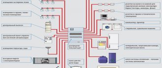
Electrical supply diagram for a private house 380V 15 kW
One of the most important stages in the construction or renovation of a country house is its electrification. In modern housing, a large number of household appliances and all kinds of equipment are installed, and all these devices consume electricity. Therefore, we have to solve such an important issue as connecting the facility to the power grid. To do this, first of all, you will need a 380V, 15 kW power supply circuit for a private house, which can be of two types - single-phase and three-phase. Both options are in demand, but recently preference has been given to a three-phase circuit, which significantly reduces the load on the network due to its even distribution in the form of three parallel lines.
Load calculation by phases
Let's say you have a 1500 W three-phase motor. Accordingly, each phase accounts for 500 W of active power. Let's assume that cos phi=0.8. Total power is: 500/0.8. It turns out that 625 W needs to be distributed to each phase.
In addition to the motor, other consumers are probably connected to the phases. For example, in addition to 500 W, 200 W lighting and a 300 W convector are connected. All powers are summed horizontally. Reactive power remains unchanged (unless loads with a reactive component are used).
Using the Pythagorean theorem, reactive power can be determined.
But in practice these are quite complex calculations. Therefore, this is calculated approximately: 625 W + 500 W = 1150 W. This amount turns out to be more than the exact calculations according to the formula, but there is nothing terrible . The calculation was made with a small margin.
In practice, for approximate calculations it is enough to add up all the total capacities and from them determine the power of the machine for the required load.
Three-phase connection
First of all, you need to prepare all the necessary documentation. It includes technical operating conditions that are issued by the organization that supplies electricity. Based on the technical conditions, design documentation for the electrical supply of the facility is drawn up.
You will need the following documents:
- Agreement with the energy supply organization.
- Inspection report of existing electrical equipment.
- Conclusion of a laboratory study of a circuit designed for a specific object.
- The act of delimiting electrical networks by balance sheet.
The project being drawn up takes into account the specifics of further electricity consumption. All consumers are divided into groups, which include sockets and lighting systems. Each group can be switched off separately if repair work is required. At this time, the other group continues to be used without causing unnecessary inconvenience to the owners.
For all groups, calculations of the maximum power consumption of electricity are performed. In accordance with this, the most optimal cross-section of conductors is selected. As a rule, lighting lines are laid with a cable whose cross-section is 1.5 mm2, and for sockets no less than 2.5 mm2 is required. Each group is connected to automatic protective devices that prevent fires in the wiring in the event of a short circuit.
Thus, if you have a connection project, you can calculate the need for materials, instruments and equipment, as well as determine the dimensions of the electrical panel in advance. The attached diagrams mark all the places where switches, sockets, stabilizing devices and other stationary equipment are located.
Direct connection can be made underground or overhead. As a rule, in private homes the second option is used, which has a number of significant advantages. In this case, you can use any connection diagrams with minimal time spent on completing the work. During further operation, overhead lines are much easier to repair. Of great importance is the cost of connection, which is much lower than when using an underground cable line.
When making an air connection, you should take into account the distance from the house to the pole, which should not exceed 15 m. In the case where the distance is greater than this, the installation of an additional pole is required. Due to this, severe sagging or breakage of the wire under the negative influence of external factors is eliminated. You should also pay attention to ensure that the wires do not interfere with pedestrians and vehicles. The mounting height of a three-phase line is at least 2.7 m or more. The wires themselves are installed on special insulators, and only then they are brought from the pole to the power panel.
It is recommended to install the power shield on the facade of the building, then the wires go from it to all rooms. If there are electrified extensions, the supply line is also supplied to them from the panel. To connect and account for consumed electricity, a three-phase meter is required. Mostly direct switching devices are used, the operating principle of which resembles a single-phase meter. In this case, you just need to correctly follow the device connection diagram located on its back cover or in the technical data sheet.
In some cases, a semi-indirect connection scheme for a three-phase meter can be used in a private house. The connection diagram is supplemented with a voltage transformer. To pay for consumed electricity, the device readings must be multiplied by the transformation ratio indicated on the transformer.
Connecting sockets
The peculiarity of 380V sockets is that they block from asymmetrical connection to avoid short circuit. The contacts are placed at an angle, they are different in size, with guide elements.
Stationary 380V sockets are produced in the following types:
- 2P+PE has two power (phase) terminals and a grounding terminal;
- 3P+PE or 3P+N is characterized by three phase terminals and one for grounding connection;
- 3P+PE+N - there are places for connecting three phases, one for zero, one more for grounding.
The sockets are interlocked to prevent switching off under load. The current strength (25, 63, 125A) for which these sockets are made is significant, and the products do not have an arc-extinguishing effect. Removing plugs under such a load is dangerous in terms of burns or burnt out sockets. The lock can be of an electronic or mechanical type.
Sockets are connected to the power cable in series, parallel or in a mixed way.
Three-phase network
The provision of alternating current to buildings is carried out through a three-phase circuit. This network structure is considered economically beneficial, since no additional two zero wires are required. When the current enters the object, it is distributed over three phases, each of which has its own zero. The division into phases can be carried out either inside a house or apartment, or by introducing three phases.
In a single-phase circuit there is a third wire, which is called grounding. It does not carry the workload and acts as a fuse, the importance of which is difficult to overestimate. In situations where a short circuit occurs, there is a risk of electric shock to residents or a fire. To prevent such troubles from happening and the current value does not become dangerous for residents and the performance of household appliances, grounding is used. Through the grounding wire, excess current in the network will flow into the ground.
We cut the cables and mount the modules
Every electrician will confirm that working with a tool specifically designed for a particular operation is easier and more enjoyable. You can cut the cables inside the shield with a regular construction knife, but if you do it with a special knife with a heel, everything turns out faster and better.
After cutting the cables, you should re-label the wires, since there will be quite a lot of them and if you get tangled in them, it will take a lot of time to restore order. When feeding cables into the shield, you should leave a length that is equal to twice the height of the shield, that is, run the cable through the entire shield, and then measure out the same amount. This measure is not wasteful: the wires inside the shield do not go in a straight line, but along an intricate curved line, and it is better to have a little extra wire left than not enough.
There are no strict rules for the arrangement of modules in the electrical panel; however, electricians usually use one of two installation schemes - linear or group. In the first case, all elements are arranged one after another in the order shown on the single-line diagram: automatic input device, RCD, automatic circuit breakers, consumer circuit breakers. Among the advantages of this location option is ease of implementation, the disadvantage is that it is difficult to find the “culprit” of the emergency situation.
If a group layout of modules is implemented in the panel, the components alternate among consumer groups: AV input, RCD, group of switches linked to this RCD. Next, the next RCD and the corresponding group of circuit breakers are installed. Such a circuit is somewhat more difficult to assemble, but the problem line is immediately visible from the triggered RCD.
How to cut cables inside a switchboard
The insulation must be removed from the inserted cores. This process is done carefully; conductive wires must not be damaged. Immediately a re-mark is made on it
This is important because there can be a lot of confusion after cutting all the wires.
Paper tape is suitable for labels. Do not forget the main rule: marks must be applied as indicated on the diagram.
In order for the cable to be sufficient for the entire length of the wiring, you need to insert it into the electrical panel and run it to its entire height. Then measure the same distance in height again. The result will be a length twice the height of the shield. This supply of cable will allow you to confidently guide it to the desired point according to all wiring rules, and excess pieces can always be cut off.