Greetings to everyone on our website. Today we will talk about the design of a current generator. Let's try to cover this topic as much as possible and consider the design of direct and alternating current generators.
In fact, it is not entirely correct to call this device an alternating or direct current generator, since current occurs only in a closed circuit. In general, EMF, not current, occurs in the generator windings. Current begins to flow only when any consumer is connected to the windings. However, in this article we will use established concepts.
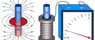
Whatever electric generators are, their main principle is the generation of electrical energy due to the rotation of the winding in a magnetic field. This means that we can distinguish two schematic types of generators: either we rotate a magnetic field in a stationary conductor, or we rotate a conductor in a stationary magnetic field.
Alternating current generator device
So, regarding the design of the alternator and the principle of its operation.
The most widespread are alternating current generators with a fixed conductor. This is due to the fact that the excitation current in relation to the current received from the generator is small. If you look at the picture, you will see two rings through which the excitation winding current flows and this is the weak link of any generator with an excitation winding. That is, either we supply a small excitation current through the rings through the brushes, or we remove a large operating current through the rings. In electricity, the stationary part of generators or motors that contains the winding is called the stator. The moving part may be called a rotor or armature.
Main types of alternating current generators
There are quite a few types of generators. Let's try to classify them according to their main areas.
- By type of energy used:
- Wind energy
- Liquid fuel energy
- Heat energy
- Water energy
Gas energy
- Single phase
Three-phase
There are other types, but they are less common.
- By type of excitation:
- Independent arousal. In this case, on the same shaft with the alternating current generator there is also a direct current generator, which powers only the excitation winding. In this case, excitation can be performed by any other current source, for example, a battery.
- Excitation using magnets that are located on the stator or armature, which greatly simplifies the design of the generator, but using this method it will not be possible to obtain powerful generators.
Self-excitation. In this case, the voltage for the field winding is obtained directly from the generator used.
Synchronous generator: circuit, device, principle of operation
What does synchronous mean in relation to a motor or generator? To put it very simply, the frequency of alternating current strictly depends on the rotation speed of the rotor of the electric machine and vice versa. In this way, the frequency of the alternating current can be controlled relatively easily. The synchronous generator itself has a number of advantages, thanks to which it has become the most widespread. I’ll tell you a big secret, it is synchronous generators that are used at all stations where electricity is produced.
The drive motor (designated as PD in the diagram) can be any rotating device: engine, turbine, windmill or water wheel impeller. On the same shaft with the PD there is a generator rotor with an excitation winding. A constant voltage is applied to the winding and a magnetic field is formed around the winding. When the rotor rotates, an EMF appears in the stator windings, that is, a voltage appears, only now variable, the frequency of which depends on the rotation speed of the rotor n1 and the number of pole pairs p. The EMF frequency can be calculated using the formula.
Asynchronous generator: circuit, device, principle of operation
Asynchronous generator device
An asynchronous generator is essentially an asynchronous motor. That is, any asynchronous motor can be switched to energy generation mode and vice versa. Structurally, the device, which is called a generator, is designed in such a way as to have good cooling. We will not dwell deeply on the principle of operation of asynchronous machines, but I will briefly tell you why they are called asynchronous using the example of a motor.
When voltage is applied to the stator windings, a magnetic field is formed; for three-phase motors it is circular, for single-phase motors it is ellipsoidal, tending to be circular. The magnetic field begins to cross the turns of the stator winding. In the short-circuited winding of the rotor, an EMF arises, that is, voltage, and since the winding is short-circuited, a current begins to flow through it, which also creates a magnetic field. The interaction of these magnetic fields causes the rotor to move. What will happen if the speed of the rotor becomes equal to the speed of the magnetic field created by the stator? That's right, the stator magnetic field will stop crossing the rotor winding. This can be compared to two cars moving at the same speed. The cars seem to be moving, but at the same time, in relation to each other, they seem to be standing still, the ground is simply rushing under the cars at high speed. So, as soon as the rotor speed and the speed of the stator magnetic field become the same, EMF will no longer be generated in the rotor winding, the interaction of the magnetic fields of the stator and rotor will stop, and the rotor will begin to stop. Therefore, the rotation speed of the rotor of an asynchronous motor is always slightly less than the rotation speed of the stator magnetic field, and this value is called slip.
So, in order for an asynchronous motor to become a generator, it is necessary to determine the slip and increase the rotor speed by this amount. Let's say we have a single-pole three-phase asynchronous motor with a shaft rotation speed of 2800 rpm. If such a motor were synchronous, the rotation speed would be 3000 rpm. That is, the sliding is 200 revolutions per minute. This means that if we start rotating the rotor at a speed of 3200 rpm, the engine will switch to generator mode and will no longer consume, but generate EMF.
The difficulty of using such generators is that they are prone to failure. For example, if you turn on a resistive load (incandescent light bulb or heater), the inrush current will be small. Significant overload will not occur and the generator will operate stably. If you turn on a reactive load, for example, an engine, then there will be a large starting current, 5-20 times higher than the rated current, which will “fail” the generator, that is, cause a sharp drop in voltage on the generator windings. After such a failure, the asynchronous generator must be excited again. So, the simplicity of an asynchronous generator is outweighed by a serious drawback.
Well, you also need a capacitor unit to excite the short-circuited rotor winding. If we choose the wrong capacitance of the capacitors, then in case of “undersupply” from the generator we will receive less current, and in case of “oversupply”, our generator will overheat greatly.
Connection diagrams
Actually, not even switching schemes, but options. There are usually three of them:
- Automatic switching on . In this case, a special emergency switching unit is installed. As soon as the voltage in the network is turned off, the unit sends a command to start the generator and switches the network from an external power source to the generator set.
- Manual activation . In this case, the user himself carries out the switching operation from the external power source to the generator set and manually starts the generator.
- Synchronous work . This mode is mainly used at large stations, the generators of which are combined into one network. All generators of this network operate synchronously, with the same frequency, with the same phase order and with the same voltage on the stator windings.
Single phase generator
I won't go into detail here. Such devices can now be found in any tool store. If a single-phase generator is used as a backup source of electricity, it is connected to the home network, usually through a switch. That is, an external power source and a generator cannot operate on the same network at the same time - it’s either one or the other. Firstly, there is no need, and secondly, it would greatly complicate and increase the cost of household generators. The only thing I can focus on here is connecting a single-phase generator to a three-phase network.
Connecting a single-phase generator to a three-phase network
However, this method has its drawback. Three-phase motors will not work in such a network; if you turn them on, they will heat up very quickly and fail.
Three phase generator
Three-phase generators can be domestic and industrial. The design of a three-phase current generator in the household version is practically no different from a single-phase one, as is the switching circuit. The only condition when connecting a household generator to a network, if there are three-phase motors in such a network, is to observe the phase order. If the load in the house is single-phase, then this precaution can be neglected.
The industrial version of a three-phase current generator device is a device equipped with an automatic start and can sometimes be equipped with a synchronization device. It is better to entrust the connection of such generators to specialists.
Well, a household generator, just like a single-phase generator, is connected to the network through a switch. Consequently, depending on the position of the switch, either an external power source or a generator operates.
Application area
It is impossible to imagine the daily life of human society without alternating current.
Its widespread use is due to the fact that it has enormous advantages over permanent. At the same time, the main advantage is that the voltage and strength of alternating current can be easily and practically losslessly converted within a fairly wide range.
Especially, such a transformation is necessary in the case of transmitting electricity over long distances. Electricity has great advantages over other types of energy.
It can be transmitted over long distances with low losses and fairly easily distributed among consumers. In addition, electricity is simply converted into other types of energy (light, heat, mechanical, etc.).
That is why alternating current generators are very widely used in modern conditions. With their help, electricity is generated, which is then used in all industries, as well as in everyday life and in all types of transport.
DC generator device
To find out what a DC generator is, its structure and principle of operation, let’s go back a little. We have already figured out how an alternator works. Let's take a closer look at the process of EMF generation. As the rotor rotates, we have a cycle equal to one revolution of the rotor, or 360°. Let's find out what happens in this cycle:
- 0° - EMF =0
- 90° - EMF reaches its maximum value with the “+” sign
- 180° - EMF is again 0
- 270° - EMF reaches a peak value with a “-” sign
How to make sure that the polarity of the voltage does not change? Great minds came up with the following idea - to use a collector, that is, to remove voltage only of the required polarity. Remember, we said that in an alternating current generator, the stator winding is the working one, and the excitation winding is located on the rotor. So, in a DC generator, voltage is removed only from the rotor, which is called the armature.
DC generator circuit
If such a generator has only one pair of poles, as in the picture, then we will get a pulsating direct voltage, where the frequency will be twice the rotation speed. That is, if the rotation speed is 50 revolutions per second, then the pulsation frequency will be 100 Hz. To reduce voltage ripple, increase the number of pole pairs.
Since the invention of the DC generator, it has remained virtually unchanged schematically and in principle of operation, only the manufacturing technology has changed and now it looks like this:
Main types of DC generators
Currently, commutatorless DC motors are gaining popularity. Is a brushless generator option possible? Unfortunately, we have not yet been able to solve this problem. So, if you see the name “Brushless DC Generator” somewhere, know that it is an AC generator with a rectifier unit.
For this reason, DC generators are characterized only by the type of excitation:
- Generators excited by magnets . Such generators cannot develop high power, so they are used only where small power is required. And, of course, the use of magnets significantly reduces the cost of such generators.
- Independent arousal. In the same way as with alternating current generators, an external power source not connected to the generator is used for excitation.
- Dependent arousal, which is divided into three types:
- Parallel excitation. As the name suggests, the excitation winding in such a generator is connected in parallel to the armature winding. Sometimes this type of excitation is called shunt.
- Consistent excitation. Here the excitation winding is connected like a garland, in series with the armature winding. This type is sometimes called serial.
- Mixed or compound excitation. The excitation winding of such generators consists of two parts, the first is connected by a shunt method, the second by a serial method.
Generators with independent excitation: circuit, device, principle of operation
Independent excitation generator circuit
The operating principle of this generator is quite simple. However, the simplicity of the generator is also its disadvantage - it requires an external independent power source. The generator armature is accelerated to the required speed, then the generator is excited using a rheostat. An EMF appears on the armature windings and when a load is connected, current begins to flow.
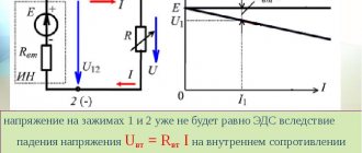
The load capacity of such a generator is very good. As a rule, the difference between the no-load voltage, when the load is not connected, and the voltage at the rated load of the generator, when the consumer is fully loading, is only 5-10%.
The advantage of a generator with independent excitation is that it can be started under load, that is, with electrical appliances connected.
Generators with parallel excitation: circuit, device, principle of operation
Parallel excitation generator circuit
A generator with a parallel connection of the excitation winding, in principle, also has good load characteristics, although somewhat worse than those of circuits with independent excitation - 10-30%. Circuits with dependent excitation have one feature: in order for excitation to occur, the metal of the generator must have residual magnetization. 2-3% of residual magnetization is enough to start the self-excitation process. Of course, in this case the direction of the excitation winding must coincide with the direction of the residual magnetization field.
The generator armature is spun up to rated speed, due to residual magnetization self-excitation occurs, that is, an EMF appears in the generator-excitation winding circuit and a small current appears. It increases the EMF, therefore the current increases again and this happens until a balance is reached between the voltage drop in the generator winding and the voltage drop in the field winding.
There is one peculiarity in the operation of the generator. If you gradually increase the load until a short circuit occurs, then at some point the generator power will reach peak values, then begin to decline. In fact, if you create a short circuit at the moment of nominal load of the generator, then nothing bad will happen. But if this is done with a small load, then the short circuit current reaches critical values of 8-10 In, which means that such generators are highly recommended to be protected from short circuits by any available method.
Such generators are most widespread because they do not require external power supplies, have good load capacity and allow control of the excitation current.
Generators with sequential excitation: circuit, device, principle of operation
Series excitation generator circuit
Since the current of the excitation winding in this case is equal to the current in the circuit, and therefore reaches large values, the excitation winding is made of thick wire and has fewer turns than in the previous two circuits. The operating principle is the same as the previous scheme. The winding and the residual magnetization field must coincide in direction. When the armature is untwisted to the rated frequency, an EMF occurs, the current rises and further increases until balance is achieved.
But there is one small nuance here. The field winding current varies depending on the load current, and there is no way to regulate the field current. And this leads to the fact that the voltage also changes greatly. Here we get a real current generator, not a voltage generator. That is why the scope of application of a generator with series excitation is very limited.
Description of circuits
To obtain a connected three-phase system, the windings of the electric generator must be connected to each other in one of two ways:
"Star"
A star connection involves electrically connecting the ends of all windings at one point. The connection point is called “zero”. With this connection, the load can be connected to the generator with 3 or 4 wires.
The wires coming from the beginning of the windings are called linear, and the wire coming from the zero point is called zero. The voltage between linear wires is called linear.
Line voltage is 1.73 times greater than phase voltage.
The voltage between neutral and any of the linear wires is called phase. The phase voltages are equal to each other and shifted relative to each other by an angle of 120 degrees.
A feature of the circuit is also the equality of linear and phase currents.
The most common 4-wire circuit is a star connection with a neutral wire. It allows you to avoid phase imbalance in the case of connecting an asymmetrical load, for example, on one phase there is an active load, and on the other there is a capacitive or reactive load. At the same time, the safety of switched on electrical appliances is ensured.
"Triangle"
A delta connection is a series connection of the windings of a three-phase generator: the end of the first winding is connected to the beginning of the second, its end to the beginning of the third, and the end of the last to the beginning of the first.
In this case, the linear wires are diverted from the connection points of the windings. In this case, the linear voltage is equal to the phase voltage, and the magnitude of the linear current is 1.73 times greater than the phase current.
All mentioned dependencies are valid only for a uniform phase load. If the load of the phases is uneven, they must be recalculated using analytical or graphical methods.
Generator power
If you turn on all the energy-intensive devices in the car, the generator may not be able to cope with the load and some of the energy will be transferred to the battery.
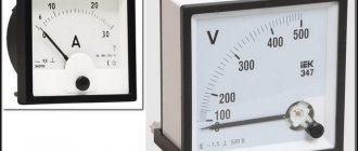
To calculate the generator power, it is enough to use a simple formula from the school course P = I * U, where P is power, I is current, U is voltage.
We learned that the voltage at the generator output should be in the region of 13.5V - 14.2V. The current strength may vary between models. On average it is from 80A to 140A. Let's take the average value of 100A.
Using the formula, we get 13.5V*100A = 1,350 W or 1.35 kW. This is the power of the generator, which is measured in Watts. It should also be taken into account that this is the maximum value that is achieved at certain engine speeds, usually from 3000 rpm and above. At idle, the power output is 75% of the maximum possible. It is believed that 80A is enough for a car. If you use a more powerful generator, the on-board network may not be able to cope with the load. We need to take this into account. More power is not always good.
Malfunctions of autogenerators and ways to eliminate them
When operating generators, mechanical and electrical faults may occur. Often, one failure that is not corrected in time becomes the cause of others.
Signs of generator damage:
- flashing or constant operation of the charging lamp when the engine is running;
- insufficient charging or overcharging of the battery;
- dim light of external light alarm;
- lamp pulsations;
- a significant increase in the brightness of the lamps with increasing speed;
- extraneous sounds, the source of which is the generator or drive.
Mechanical breakdowns
Common mechanical faults:
- the appearance of cracks on the drive pulley;
- drive belt break;
- wear of the armature bearings, which leads to jamming of the generator.
Cracks and chips on the pulley are detected during a visual inspection of the unit. The sharp edges begin to destroy the drive belt, which can come off the pulley along the damaged edges. A broken or burst pulley must be replaced with a new one; repair of the unit is impossible. The new pulley must have the same geometric parameters as the worn one.
Damaged armature bearings begin to emit a characteristic whistle during operation. You should not delay repairs, since the operating mode of the generator is disrupted due to a change in the gap between the armature and the stator. As a result, the armature may jam, which will lead to belt breakage and damage to the brushes and windings.
Electrical breakdowns
Failures of the electrical part of generators:
- abrasion of current collecting brushes;
- wiping the commutator part of the generator rotor;
- failure of the voltage regulator;
- interturn short circuits of the stator winding;
- burnout of the rectifier diode bridge;
- destruction of connecting wiring;
- burning or oxidation of wiring connections.
To check the functionality of the generator, use a multimeter or voltmeter designed to measure a direct voltage of 0-20 V. Before starting measurements, it is recommended to warm up the unit by letting it run for 10-15 minutes with the engine idling and the consumer running (for example, low beam headlights). Measuring the voltage between the positive terminal of the generator and the vehicle ground should show a value in the range of 13.5-14.5 V. More accurate information is available in the repair and maintenance instructions for the car. If the voltage deviates from the standard, the relay regulator must be replaced.
Checking the voltage at the battery terminals allows you to detect damage to the connecting wiring. For a full measurement, it is necessary to increase the engine speed to high and connect powerful energy consumers (for example, high beam headlights, heated windows and seats). In this case, the voltage should be close to the value on the relay regulator. Otherwise, it is necessary to check the wires and connection points.
The serviceability of the diode bridge is checked by installing a multimeter on the positive terminal of the generator and ground in AC measurement mode. The voltage value should be within 0.5 V. A higher voltage is a sign of a faulty diode bridge.
The process of replacing the generator on a Ford Focus 2 is shown in a video provided by the ABC Ford channel.
Measuring breakdowns of the generator windings is carried out with the battery disconnected and the wiring disconnected from the positive terminal of the device. The tester, switched to ammeter mode, is connected between the terminal and the wiring. A value of up to 0.5 mA is considered acceptable. With increased current, breakdown of parts of the diode bridge or windings is possible.
To check the field windings, it is necessary to remove the generator from the car. Work is being carried out with a remote voltage regulator and brush assembly. Before starting the test, the slip rings are cleaned of dirt. Testing is performed with a multimeter set to ohmmeter mode. The connection is made to slip rings. The normal resistance value is in the range of 5-10 ohms. To measure the breakdown to ground, an ohmmeter is attached to the rings and body. In good condition, the resistance value will be infinite; with other values, there is a breakdown.
It is strictly forbidden to check the operation of generators using the short circuit method. Such actions lead to failure of not only the unit, but also the electronic components. It is recommended to carry out diagnostics of the device on stands available in specialized centers. Doing it yourself can result in costly repairs.
Giant hydroelectric power plants
One of the most powerful hydroelectric power stations in the world was built in China on the Yangtze River and was called the “Three Gorges”. Its concrete dam is 2309 m long and 185 m high. The total power of the station's electric generators is almost 23 MW (1 MW = 1 million W). Over the course of a year, they generate about 100 billion kWh of electricity.
Only slightly less electricity is generated by the Itaipu hydroelectric power station, located on the Parana River (on the border of Brazil and Paraguay), which has the largest dam. The height of this gigantic structure reaches 196 m, and the length is 7235 m.
Share link
Excitation structures
Any turbo, hydro, diesel generators, synchronous compensators, motors produced at the moment are equipped with the latest semiconductor structures, such as excitation of synchronous generators. These structures use the method of rectifying three-phase alternating currents of high or industrial frequency exciters or the voltage of the excited unit.
The design of the generator is such that the excitation structures can provide such unit operating parameters as:
- The first stage of excitement, that is, the initial stage.
- Idle work.
- Connecting to the network using precise synchronization or self-synchronization.
- Work in the energy structure with existing loads or overloads.
- The excitation of synchronous devices can be forced according to criteria such as voltage and current having a given multiplicity.
- Electric braking of the device.
Generator power
If you turn on all the energy-intensive devices in the car, the generator may not be able to cope with the load and some of the energy will be transferred to the battery.
To calculate the power of the generator, it is enough to use a simple formula from the school course P = I * U, where P is power, I is current, U is voltage.
We learned that the voltage at the generator output should be in the region of 13.5V - 14.2V. The current strength may vary between models. On average it is from 80A to 140A. Let's take the average value of 100A.
Using the formula, we get 13.5V*100A = 1,350 W or 1.35 kW. This is the power of the generator, which is measured in Watts. It should also be taken into account that this is the maximum value that is achieved at certain engine speeds, usually from 3000 rpm and above. At idle, the power output is 75% of the maximum possible. It is believed that 80A is enough for a car. If you use a more powerful generator, the on-board network may not be able to cope with the load. We need to take this into account. More power is not always good.