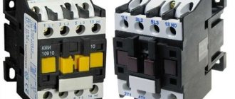
Design features and main characteristics
Let's look at how a contact box is structured using the example of a CI ultrasound (see Fig. 2)
Figure 2. Location of contacts in the ICC
Contacts marked 0, A, B and C are used for the power circuit, and terminals numbered 1 to 7 are used for the current section. How to enable instrumentation will be described in the next section.
The instrumentation design is a contact group housed in a plastic box made of impact-resistant and non-flammable polycarbonate. The dimensions of this model are 68x220x33 mm.
Operating voltage and current parameters are 380 V and 16 A. The insulating properties of the material allow it to withstand short-term excesses of up to 2000 V and 25 A. Brass is used to make live parts. It can be replaced with galvanized steel, but the service life of such contacts becomes shorter. In this regard, manufacturers of famous brands prefer brass.
Other performance characteristics:
- the module can be used at temperatures from -40 C° to 60 C°;
- permissible humidity – no more than 98%;
- for connection, wires with a minimum cross-section of 0.5 mm 2 and a maximum cross-section of 4 mm 2 are used;
- this model is available with a degree of protection IP20;
- service life - up to 30 years.
Some models (for example, BTS or KIP-5/25) are available with a transparent cover (see Fig. 3). Considering that devices of this type are subject to mandatory sealing, this design feature has obvious advantages, since it allows you to monitor the condition of a group of contacts.
How to disconnect and connect a metering device or a model device
When performing a replacement, it is necessary to follow the order of actions; we will begin the description with the shutdown procedure.
How to disconnect?
This is done in the following order:
Connecting a new metering device. After complete dismantling has been completed, you can begin the installation procedure; it is performed in the reverse order, namely:
Why is bypass surgery necessary?
We consider it necessary to give a small explanation about the need to close the CT output coil. This is due to the characteristic features of such devices; it is impossible to allow the CT to operate at idle with the secondary winding open. If this condition is not met, a large EMF will be induced on it, which can not only lead to an interturn short circuit, but also pose a danger to human life or health.
Connecting a sample fixture.
The algorithm of actions in such a situation will take the following form:
To carry out a test measurement it is not at all necessary to disconnect the control device from the box. Design features allow you to connect without removing the device under test. To do this, the control device is connected to the lower contact groups of the box, and the current jumpers are not installed in place. As a result, the standard metering device will remain in place, but will not be connected to the TT.
Theoretically, it is possible not to disconnect the current jumpers, but then there will be a fairly high probability of the standard device influencing the readings of the model device.
What must be taken into account when working with instrumentation?
The connected test box contains voltage that is dangerous to human life. Therefore, to work with this device you must have the appropriate tolerance level (up to 1000 volts).
Since this device is subject to mandatory sealing, only persons who have permission to carry out such work can be allowed to manipulate it. When the switching is completed, the box is sealed again.
Source
Device design
ICC design
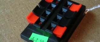
Typical transition boxes are available in several designs, differing in appearance and shape. Most often they have the form of a rectangular block with thick walls made of durable and non-flammable material (carbolite or plastic). In this design, the box resembles a substrate with groups of terminals placed on it, forming the so-called “clamping cage”.
Through holes are made along its edges, used for attaching the IKK to the walls of the distribution board. Its connecting contacts are made of brass or galvanized steel (sometimes phosphor bronze is used for this). Some box models are equipped with additional elements such as a flange or lever, which simplifies the installation process.
Transition contacts are made in the form of spring-loaded plates or screw clamps placed on conductive plates made of brass, tin or steel. Their use is explained by the resistance of these materials to corrosion and high conductivity. The top of the block is closed with a transparent plastic cover, securely fixed to the base. When operating the test device together with an electric meter, its cover is also sealed. For this purpose, it is provided with through ears for hanging a seal or a small hole for a control screw (screw). The transparency of the protective coating allows you to visually control the disconnection of contact groups.
ICC box design
Enterprises produce test boxes of various types and shapes. But mostly you can find rectangular plates made of durable shockproof and fireproof composition. Carbolite or high-strength plastic is used as fireproof raw materials.
Installation in the panel
This plate looks like a substrate on which the terminal blocks are located, creating a clamping circuit. At the boundaries of the block there are small holes used for fixing the ICC to the electrical box.
Note! For the production of electrical contacts, tin or carbon steel, as well as heat-resistant bronze and copper are used. Many types of test boxes are equipped with additional parts, such as a spigot or a handle, to simplify installation
The transition parts are similar to spring gear or iron platforms. These elements are located on current-conducting plates made of copper, tin, and steel. These materials are resistant to temperature and humidity changes and are quite durable.
If the use of a test box is necessary to connect an energy meter, then a seal is placed on the lid; for this purpose it is equipped with small holes for sealing or holes for a control part. Thanks to the transparent cover, you can monitor the visual status of the device. The rules for connecting blocks to energy metering devices are described in detail below.
How to avoid 4 problems when operating three-phase Mercury meters
Most often, problems with the operation of Mercury meters concern the liquid crystal display (LCD). A malfunction of the device is indicated by an error code on the device. They can be temporary or permanent. Incorrect operation of the metering device is corrected.
- If the memory function is impaired, it is necessary to find out the associated code and reprogram the option.
- If a CS program error is detected, you need to urgently send the device to the manufacturer. Most of the identified violations of the CS program will be eliminated only there.
- The tarifficator byte KS error can be easily corrected by restarting the device.
- The inaccuracy of the CS of the array of accumulated energy registers is eliminated by resetting the energy registers.
Terms of use
Installation, dismantling, opening and installation of seals on the box are carried out only by specialists in this field who have a license obtained from Energonadzor and have received the required level of permission to work.
All test boxes can be classified according to different characteristics. To begin with, they are divided by the type of network where they will be used.
Next you can find boxes necessary for use in 220 V and 380 V networks. They are also distinguished by weight, appearance, and size.
Connecting transformers to electricity
IKK test boxes can be round, oval or square. In addition, they are divided by:
- purpose. For use in conjunction with instrumentation or for switching operations only;
- installation method. You can find boxes used for mounting in a distribution block;
- number of contact categories. Produced ICCs can have three or more electrical contacts;
- type of fastening. There can be screw, push, barrier and fixed fastenings. Also, some devices have cable protection;
- number of contact rows. Can be with one or more tiers;
- execution - straight and angular;
- type of cable used.
Note! The main difference between the boxes is always the diagram by which they are connected. Depending on the factory and application, the ICC can be connected in different ways
All major energy companies are involved in the creation and distribution of test boxes. The main differences may lie in the materials used in manufacturing.
Unless a person has the appropriate tools or electrical skills, it is not advisable to attempt to install the test adapter box yourself. Incorrect installation may lead to incorrect operation of the meter or short circuit of the wires. If a defect in the wires or terminal blocks is discovered through the transparent cover, then you need to call a specialist to your home immediately.
Important! You are not allowed to break seals yourself. This is done by a specialist with permission
Arbitrariness may result in fines being imposed.
Many craftsmen recommend purchasing devices with additional protection for the wires so that in the event of a fire the fire does not pass through them. The cost of such products varies within 250 rubles. Products made from more expensive material have a price from 300 to 500 rubles.*
Adapter box connection diagram
You can connect the IKK yourself without any difficulties. But only a special person can perform opening and sealing. Such a box will help not only simplify the work with the meter, but also make it safer.
*Prices in the article are for April 2022.
Typical differences
Test box in the electrical panel
All test terminal boxes are primarily distinguished by the type of mains supply. In accordance with this indicator, they are divided into the following types:
- pads installed in 380 Volt power circuits;
- the same products, but designed for 220 Volts;
- low-voltage samples intended for installation in a 110 Volt network.
Products are usually distinguished by shape and working dimensions. According to these characteristics, they can be round, rectangular or square, small in size or in an enlarged series.
In general, test boxes are classified according to the following characteristics:
- appointment;
- installation method;
- number of rows on the substrate;
- the number of contact groups in each of them;
- type of fixation and brand of wire;
- execution (corner boxes or straight).
According to their intended purpose, the products are used together with meters or are intended for ordinary switching operations. They can be mounted on a DIN rail or installed in a cross-module. The possible number of rows and contact groups in these devices is one or two with a number of contacts of 3 or more.
Depending on the fixation method used, all boxes are available for screw, barrier and fixed (push) fastening. The brand of wire to be connected is selected depending on the type of terminals used in the box. Screw and end clamps are suitable for all types of conductors, while spring and knife clamps usually accept their solid counterparts. However, the main difference between test blocks for meters is in the connection diagram, according to which they are used for one metering device or for several samples at once.
IKK test boxes are produced by most major manufacturers of electrical equipment, using various materials in their manufacture. This fact is confirmed by the presence of various quality certificates for a number of products.
Test box: transition box for electric meters, box installation
When installing measuring instruments in three-phase power circuits, special attention is paid to bringing the controlled quantities to a form convenient for connection to an electric meter. For significant current loads reaching 1000 Amperes, special converting devices are used for this - current transformers (CTs)
For significant current loads, reaching 1000 Amperes, special converting devices are used for this - current transformers (CTs).
If they are present, maintenance and repair of metering devices connected to the line becomes significantly more complicated.
Purpose and features of IKK
Test box for meter
The PUE specifically stipulates the requirement regarding the connection of the meter to existing electrical networks in terms of its switching through a device called a test box (TBC). When using it, it is possible to short-circuit the secondary circuit of the measuring transformer, which makes it possible to de-energize the supply lines for each of the phases supplied to the meter.
Connecting the current transformer through the test box allows you to turn the procedure for replacing and checking the meter into a completely safe activity. In addition, in this case it is not necessary to disconnect the load from the supply line.
Electricity meter test boxes are especially in demand in the following situations:
- for bypassing control circuits;
- if there is a need to completely disable them;
- if necessary, block voltage in each phase;
- for connecting a measuring device (electricity meter) to a controlled line.
The need for IKK boxes is also explained by the fact that there is a special group of consumers, each of whom cannot be disconnected from the power grid even for a short time.
Taking into account the fact that periodically there is a need to carry out work with the meter, the IKK test terminal box significantly simplifies all operations.
In this case, there is no need to de-energize the power line and install a replacement shunt in place of the measuring device.
Installation diagram
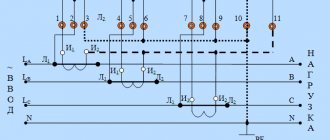
The figure below shows the electrical diagram for connecting the meter through the test terminal box:
As can be seen from the diagram, a wire connected to a three-phase power source through current transformers comes to the terminals in the block marked A, B, C. The neutral wire is connected to a separate terminal. Next, a metering device is connected from these terminals using wires, subject to the following conditions:
- transformers are connected in a star configuration, and their common terminal is grounded;
- Wires with a cross-section of at least 1.5 mm² are laid from the current converters to the junction box;
- Three wires with a cross section of 2.5 mm² are connected from the electricity meter;
- for convenience, all wires are marked - three phases and the beginning of the current windings and the common terminal are indicated.
Since the circuit does not assume direct contact of the current transformer terminals with the meter terminals, it is necessary to monitor the switching order.
The meter terminals are connected in the following order:
- A wire from the current winding of the first phase transformer is connected to 1 terminal
- a wire is connected to the second terminal of the meter - the voltage of the first phase;
- a wire from the current winding of the second phase is connected to the 4th terminal of the meter;
- voltage of the second phase is connected to 5;
- 7 - incoming wire of the current winding of the third phase;
- 8 - third phase voltage;
- 9 - common wire;
- 10 - reserve.
Jumpers are installed between the third and sixth terminals, as well as between the sixth and ninth terminals in the meter.
To safely remove the meter, it is necessary to bypass the current circuit to ensure reliable contact of the box screws with the insulated busbar. This bus is located on the back side and by screwing in the screws as shown in Figure 2, you will ensure contact.
Next, you need to loosen the jumper screws to open the jumpers. After this, remove the jumpers from the power section to turn off the voltage at the meter terminals. Next, the meter is turned off and removed. Connection is in reverse order.
We also recommend watching videos that clearly demonstrate various methods of connecting an IKK box to an electric meter:
You probably don't know:
- Types of Terminal Blocks
- How to assemble a three-phase shield with your own hands
- How to connect a magnetic starter
Nuances of use
Although this type of product does not require additional maintenance, it is still recommended to tighten the contacts some time after commissioning, especially in the case of screw terminals. This is due to the fact that during operation the wire heats up and is slightly deformed, and this leads to a weakening of the contact. There is no such requirement for clamp boxes. At the same time, it will be more convenient to use, since when you turn off the measuring device, no additional tools will be needed.
But it is also worth noting that installation, dismantling, opening and sealing of the box must be carried out by specialists who have a certificate issued by Energonadzor and who have received the required clearance group.
Adapter test box - purpose, characteristics, connection options
According to accepted standards, there is a special group of consumers who cannot be disconnected from the power supply system even for a short time. But what to do when a three-phase meter needs to be replaced for metering circuits or a testing laboratory needs to perform verification using a reference control device?
Under the conditions described above, refer to the first section in the code of practice for electrical installations. It states that to connect a meter with a current transformer (the abbreviation “CT” will be used in the text), an adapter test box must be installed, for example, such as in Figure 1.
Figure 1. KI-10 (LIMG.301591.009)
What can it be used for?
As mentioned above, instrumentation is mainly used if you need to connect a meter via a TT. This test box also allows the following:
• bypass the current circuit
• disconnect the current circuit
• disconnect the circuit for each specific phase
• connect a three-phase induction and electronic meter
• turn on the reference meter for testing without disconnecting the consumption load.
All this allows you not to remove voltage from the electrical installation when the meter is being replaced. You also don’t have to disconnect the consumer’s load if you need to connect a sample meter to check it.
Next we will take a closer look at how the process of connecting such a test box occurs.
Scope of use of test boxes
ICC for an electricity meter can most often be found when:
- shunting control circuits;
- network blackout;
- if you need to block the voltage in a certain phase;
- during connection to the controlled line of the measuring device (electricity meter).
The need to use test boxes is also explained by the fact that there is a certain category of consumers, each of which is not allowed to be de-energized even for a short period of time.
For your information! Due to the fact that it is constantly necessary to work with the meter, the test terminal block greatly facilitates all actions. In this case, there is no need to disconnect the entire power line and install a replacement shunt in place of the measuring device.
The parameters and properties of transition boxes are described in detail below. When purchasing, you must select a device that matches the specific characteristics of the meters.
Brief information
LLC NPO "MMK" was registered on January 14, 2008 by the registrar Inspectorate of the Federal Tax Service for the Verkh-Isetsky district of Yekaterinburg. Head of the organization: liquidator Guseva Inessa Vitalievna. The legal address of LLC NPO "MMK" is 620041, Sverdlovsk region, Ekaterinburg, Uralskaya street, building 57 building 2, apartment 41.
The main activity is “Production of other finished metal products not included in other groups”; 15 additional types of activity are registered. The organization LIMITED LIABILITY COMPANY RESEARCH AND PRODUCTION ASSOCIATION “METMASHKOM” was assigned TIN 1222398117, OGRN 3273383369108, OKPO 25164177.
The organization LIMITED LIABILITY COMPANY RESEARCH AND PRODUCTION ASSOCIATION "METMASHKOM" was liquidated on October 12, 2022. Reason: Liquidation of a legal entity.
Transition test box (CTB)
Hello, dear readers and guests of the Electrician's Notes website.
In many of my articles, especially about connecting meters through current transformers, I mentioned to you about the test adapter box (terminal block). In short, KIP.
So today I would like to talk about it in more detail.
So, what is this box (terminal block) for?
In Chapter 1.5, clause 1.5.23 of the PUE 7th edition it is said that electrical energy metering circuits must be connected to special clamps or test boxes (terminal blocks).
By the way, anyone who wants to test their knowledge or prepare for an electrical safety exam online, I suggest doing so directly on the website. For you, I have specially prepared a whole section “Online tests on electrical safety” for different groups.
The test adapter box (TUB) is intended for:
- the ability to “short-circuit” (bypass) current circuits
- disconnecting current circuits
- disconnecting voltage circuits for each phase
- connection of a standard electric meter
The first three points are necessary to replace the electric meter without removing the voltage from the electrical installation. The last point applies to connecting a model or reference electric meter in order to check the metering device without disconnecting the consumer’s load.
The photo above shows a transition test box that meets the technical specifications MKYUR.301 591.000 TU. It has the following technical characteristics:
- voltage up to 380 (V)
- maximum current up to 10 (A)
- degree of protection - IP20
- weight - about 500 (g)
- overall dimensions of the box 33x68x220
Test box connection diagram
Below see the diagram for connecting the meter through the test terminal block to a four-wire 380/220 (V) network:
And here is a photo from above of the adapter terminal block with the designation of terminal numbers:
To “short-circuit” (bypass) current circuits, you simply need to screw M4 screws into the following holes:
In the photo above, the screw on terminal 1 is not screwed in, but on terminals 2, 4 and 6 the screw is screwed in.
When screwed in, these screws complete the circuit through a common busbar located on the back of the terminal block.
By the way, to protect the common busbar from short circuits to the housing, a cardboard gasket is used on the reverse side.
After the current circuits are short-circuited, you can remove (remove) the jumpers.
To disconnect the voltage circuits for each phase, you need to unscrew the screws and remove the corresponding jumper.
I forgot to mention that all jumpers and terminals at the transition test box (CTB) are made of brass, because... it is less susceptible to corrosion and also has better electrical conductivity compared to steel.
The test box is closed with a lid with a screw for sealing.
Instrument covers are either black (not transparent) or transparent. The latter has a significant advantage in that the state (position) of the contacts and the connection diagram of the meter can be seen without opening it.
Example of connecting a test adapter box (TUB)
Below I will give you an example of connecting a test box. A few days ago I installed electricity meters on two input cells of the boiler station, which were later connected to the ASTUE system.
The metering panel was installed on the wall near the ASU assembly.
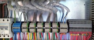
Meters, test and interface boxes are also installed there. Metering circuits (current circuits and voltage circuits) are connected to current transformers and ASU buses using PV-1 copper wires with a cross-section of 2.5 square meters. mm, laid in corrugation.
I will not go into detail on the meter connection diagram, because... I recently wrote an article about connecting a three-phase meter through current transformers to a four-wire 380/220 (V) network, in which you can familiarize yourself with everything in detail.
In conclusion, I recommend that you watch my video, where I more clearly talk about connecting the test box using the example of a Mercury 230 ART-03 meter connected through three current transformers to a 400 (V) network:
Addition. In this article I looked at one of the options for connecting a test box. In practice, there is another common scheme, which I describe in detail in the video (using the example of a Mercury 230 AM-03 meter connected through three current transformers to a 400 V network):
What is important to know
Relay automation
Requirements for devices and connection circuits are indicated in GOST. Manufacturers cannot deviate from these requirements, since their metering devices must be certified accordingly and undergo state verification. For example, according to clauses 4.1 and 4.2 of GOST 31818.11-2012 (IEC 62052-11:2003), standard and permissible voltage and current values are defined for direct and transformer-connected meters. The most commonly used in 0.23 and 0.4 kV networks are direct connection meters and transformer connection meters with current transformers. Voltage transformers are usually used in electrical installations at higher voltage levels.
Direct connection meters in accordance with the specified GOST have standard current values of base and rated currents of 5, 10, 15, 20, 30, 40, 50 A and permissible current values of 25, 80, 100 A.
For transformer connection meters, standard current values are set at 1, 3, 5 A. The permissible current values for such meters are 0.2; 0.3; 0.6; 1.0; 1.5; 2.0;2.5; 5.0; 10.0 A.
What does standard and permissible current mean? The standard value of the base current is used for meters with direct connection - it is the initial value for establishing the requirements for this type of meters.
The standard rated current value applies to meters operating through a transformer, and the rated current of the meter must be equal to the rated current of the secondary winding of the current transformer. This requirement is given in clause 1.5.19 of the PUE (Chapter 1.5).
Permissible currents contain a wider range of data
When choosing current transformers and meters, pay attention to these nuances
Electricity meters can be switched on using a test box. In the PUE clause 1.5.23, it is recommended to connect metering circuits to independent assemblies of clamps or sections in the general row of clamps. If this is not possible, then test boxes are used for metering circuits. During installation, it is necessary to ensure that the secondary windings of the current transformers are short-circuited when checking or replacing them. Current circuits of meters and voltage circuits in each phase must be turned off without disconnecting wires and cables.
It is mandatory, in accordance with the same paragraph of the PUE, that test boxes and clamp assemblies must be able to be sealed.
The design of the IKK must provide for the possibility of connecting a reference metering device.
Device installation
IKK installation diagram
The devices are in demand when laying new electrical lines and when it is necessary to modernize them. During installation, the requirements of the PUE regarding the rules of operation of test boxes must be met. According to the regulations, to place the ICC it will be necessary to prepare a specially equipped place, protected from entry by unauthorized persons and accessible to service personnel.
It is allowed to connect only wires made of homogeneous metals that are electrochemically compatible at the terminals of the box.
The tightening force for contact screw connections should not exceed 2.5 Nm, which guarantees the safety of the terminals. In addition, they must not have any damage or traces of obvious defects. Fixing the IKK body at the installation site is carried out only mechanically - by screwing it or securing it using special latches. The box is usually mounted in the electrical cabinet immediately after the electric meter.
