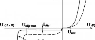
At the initial moment, a slightly higher voltage is required to initiate the arc than during its subsequent combustion. This is explained by the fact that when an arc is excited, the air gap is not heated enough, the degree of ionization is low, and a voltage is needed that can impart such energy to free electrons that ionization can occur when they collide with atoms of the gas gap. An increase in the concentration of free electrons in the arc volume leads to intense ionization of the arc gap, and hence to an increase in its electrical conductivity. As a result, the voltage drops to the value required for stable arcing.
The dependence of the arc voltage on the current and the welding circuit is called the static current-voltage characteristic of the arc.
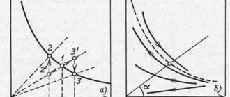
The current-voltage characteristic of the arc (Fig. 8, a) has three regions: decreasing 1, hard 2 and increasing 3. In region 1 (up to 100 A), with increasing current, the voltage decreases significantly. This occurs due to the fact that as the current increases, the cross-section and, consequently, the conductivity of the arc column increases. In region 2 (100.1000 A), as the current increases, the voltage remains constant, since the cross-section of the arc column and the area of the anode and cathode spots increase in proportion to the current. The region is characterized by a constant current density. In region 3, the voltage increases due to the fact that an increase in current density above a certain value is not accompanied by an increase in the cathode spot due to the limited cross-section of the electrode. The arc of region 1 burns unstable and is therefore of limited use. The arc of area 2 burns steadily and ensures a normal welding process.
The current-voltage characteristic of the arc during manual arc welding of low-carbon steel (Fig. 8, b) is presented in the form of curves a (arc length 2 mm) and b (arc length 4 mm). Curves c (arc length 2 mm) and d (arc length 4 mm) refer to automatic submerged arc welding at high current densities.
The voltage required to initiate an arc depends on the type of current (direct or alternating), the length of the arc gap, the material of the electrode and the edges being welded, the coating of the electrodes and a number of other factors. The voltage values that ensure the occurrence of an arc in arc gaps equal to 2.4 mm are in the range of 40.70 V.
The arc length is the distance between the end of the electrode and the surface of the weld pool. “Short” is an arc 2.4 mm long. The length of a “normal” arc is 4. in mm. An arc more than a mm long is called “long”.
The optimal welding mode is ensured with a short arc. With a long arc, the process proceeds unevenly, the arc burns unsteadily, the metal passing through the arc gap is more oxidized and nitrided, and the waste and spattering of the metal increase.
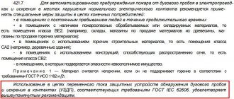
An electric welding arc can deviate from its normal position under the influence of magnetic fields that are unevenly and asymmetrically located around the arc and in the part being welded. These fields act on moving charged particles and thereby affect the entire arc. This phenomenon is called magnetic blast. The effect of magnetic fields on the arc is directly proportional to the square of the current and becomes noticeable at welding currents of more than 300 A.
The deflection of the arc is influenced by the location of the current supply to the part being welded (Fig. 9, a, b, c) and the inclination of the electrode (Fig. 9, d). The presence of significant ferromagnetic masses near the welding arc also disrupts the symmetry of the magnetic field of the arc and causes the arc to deflect towards these masses.
Magnetic blast in some cases complicates the welding process, and therefore measures are taken to reduce its effect on the arc. Such measures include: welding with a short arc, supplying welding current at a point as close as possible to the arc, tilting the electrode in the direction of the magnetic blast, placing ferromagnetic masses at the welding site.
When using alternating current, the anode and cathode spots change places with a frequency equal to the frequency of the current. Over time, the voltage and current periodically change from zero to the highest value, as shown in Fig. 10. When the current value passes through zero and the polarity changes at the beginning and end of each half-cycle, the arc goes out, the temperature of the active spots and the arc gap decreases. As a result, deionization of gases occurs and the electrical conductivity of the arc column decreases. The temperature of the active spot located on the surface of the weld pool drops more intensely due to the removal of heat into the mass of the base metal. Re-ignition of the arc at the beginning of each half-cycle is possible only at an increased voltage, called the ignition peak. It was found that the ignition peak is slightly higher when the cathode spot is on the base metal. To reduce the ignition peak, facilitate arc re-ignition and increase the stability of its combustion, measures are used that reduce the effective ionization potential of gases in the arc. At the same time, the electrical conductivity of the arc after its extinction remains longer, the ignition peak is reduced, the arc is more easily excited and burns more steadily.
These measures include the use of various stabilizing elements (potassium, sodium, calcium, etc.) introduced into the arc zone in the form of electrode coatings or in the form of fluxes.
The phase shift between voltage and current is important: it is necessary that when the current passes through zero, the voltage is sufficient to initiate the arc.
Source: asv0825.ru
Current-voltage characteristics of the welding arc
Matching the selected power source
| Current-voltage characteristic of the arc | External current-voltage characteristic of the power source | |||
| Steeply falling | Sloping | Tough | Increasing | |
| Falling | corresponds | corresponds | does not match | does not match |
| Tough | corresponds | corresponds | does not match | does not match |
| Increasing | does not match | does not match | corresponds | corresponds |
Static current-voltage characteristic of the arc
called the dependence of electrical voltage on current at a constant arc length.
The arc voltage at low current densities in the electrode drops with increasing current (falling static characteristic), then with increasing current density in a certain interval it remains almost constant (hard characteristic), and then increases with increasing current in the arc (increasing characteristic).
How to adjust arc length
Not only electrical quantities, but also the quality of welding depend on this parameter. They strive to make the arc as short as possible, within 3-4 mm.
With a longer length, the following negative phenomena are observed:
- Drops of molten metal from the electrode on the way to the weld pool manage to absorb a lot of oxygen and nitrogen from the air. As a result, the seam loses strength, ductility and toughness.
- The discharge moves along the surface of the workpiece (wandering), as a result of which the heat is distributed over a relatively large area. The penetration depth decreases; drops of melt from the consumable, falling on unheated metal, do not merge with it, but bounce off.
We recommend reading Silumin: composition, properties, application of the alloy
A short arc produces a dry crackling sound, reminiscent of oil sizzling in a hot frying pan.
With a long welding arc, negative phenomena are observed.
The seam she made looks neat and has the following characteristics:
- Correct form.
- Smooth convex surface.
The seam, made with a long arc, has uneven outlines, and drops of molten metal stick along it.
The consumable electrode decreases during the welding process. Therefore, it is gradually brought closer to the workpiece so that the discharge length remains constant.
Current-voltage characteristics of the welding arc
The dependence of the arc voltage at a constant arc length on the strength of the welding current is called its volt-ampere characteristic.
In the current-voltage characteristic, three regions are distinguished (Fig. 5.13). Region / is the region of low currents (
Rice.
5.13. Static current-voltage characteristic of the welding arc
It corresponds to a falling characteristic,
since with increasing current the volume of heated gas increases (the cross-sectional area of the arc column increases) and the degree of its ionization, the electrical conductivity of the arc increases, and the resistance of the arc column decreases. As a result, the voltage required to maintain the arc discharge drops. A welding arc with a falling current-voltage characteristic has low stability.
In area II
with a further increase in current, the arc column is somewhat compressed and the volume of gas involved in charge transfer decreases.
This leads to a decrease in the rate of formation of charged particles. The arc voltage becomes slightly dependent on the current, and the current-voltage characteristic becomes rigid.
The falling and hard characteristics correspond to manual arc welding with covered electrodes and welding with a non-consumable electrode in shielding gases.
Region III -
This is a region of high currents, and the degree of ionization here is very high.
As the current increases, intense compression of the arc column occurs, its voltage increases, and the current-voltage characteristic becomes increasing.
This characteristic corresponds to submerged arc welding and gas-shielded welding with thin wire and high-density currents.
The dependence of the voltage in the welding arc on its length is described by the equation
where a -
sum of voltages at the anode and cathode, V;
b is
the voltage drop in the arc column per 1 mm of its length, V/mm;
1A -
arc length, mm.
As the length of the arc increases, its voltage increases, and the curve of the current-voltage characteristic of the arc rises higher, maintaining its shape.
Source: studref.com
To main§ 8. WELDING PROPERTIES OF ARC
A welding arc is a powerful, stable electric discharge in a gas environment formed between the electrodes, or between the electrodes and the product. The welding arc is characterized by the release of a large amount of thermal energy and a strong light effect. It is a concentrated heat source and is used to melt base and filler materials. Depending on the environment in which the arc discharge occurs, there are: an open arc burning in the air, where the composition of the gas environment of the arc zone is air mixed with vapors of the metal being welded, the material of the electrodes and electrode coatings; a closed arc burning under a submerged arc, where the composition of the gaseous medium of the arc zone is a pair of base metal, wire and protective flux; an arc burning in an environment of protective gases (the gaseous environment of the arc zone includes an atmosphere of protective gas, pairs of wire and base metal). The welding arc is classified by the type of current used (direct, alternating, three-phase) and by the duration of combustion (stationary, pulsed). When using direct current, an arc of direct and reverse polarity is distinguished. With direct polarity, the negative pole of the power circuit - the cathode - is located on the electrode, and the positive pole - the anode - is on the base metal. With reverse polarity, the plus is on the electrode and the minus is on the product. Depending on the type of electrode used, the arc can be excited between consumable (metal) and non-consumable (carbon, tungsten, etc.) electrodes. According to the principle of operation, arcs can be of direct, indirect and combined action (Fig. 14).
Straight arc
called an arc discharge occurring between the electrode and the product.
An indirect arc
is an arc discharge between two electrodes (atomic-hydrogen welding).
A combined arc
is a combination of a direct and indirect arc. An example of a combined arc is a three-phase arc, in which two arcs electrically connect the electrodes to the workpiece, and the third burns between two electrodes isolated from each other. The arc is excited in two ways: by touching or by striking, the essence of which is shown in Fig. 15.
In a welding arc, the arc gap is divided into three main regions: anodic, cathodic and arc column. During the arcing process, there are active spots on the electrode and base metal, which are more heated areas of the electrode and base metal through which the entire arc current passes. The active spot located on the cathode is called cathode
, and the spot located on the anode is
anodic
.
The total length of the welding arc (Fig. 16) is equal to the sum of the lengths of all three areas:
L
d =
L
k +
L
c +
L
a,
where L
d - total length of the welding arc,
cm
;
L
k is the length of the cathode region, equal to approximately 10-5
cm
;
L
с - length of the arc column,
cm
;
Ld
is the length of the anode region, equal to approximately 10-3 ÷ 10-4
cm
. The total voltage of the welding arc is composed of the sum of the voltage drops in individual areas of the arc:
U
d =
U
k +
U
c +
U
a,
where U
d - total voltage drop across the arc,
in
;
Uk
is the voltage drop in the cathode region,
in
;
U
c is the voltage drop in the arc column,
in
;
U
a is the voltage drop in the anode region,
in
. The temperature in the welding arc column ranges from 5000 to 12,000° K and depends on the composition of the gaseous medium of the arc, material, electrode diameter and current density. The temperature can be approximately determined using the formula proposed by Academician of the Academy of Sciences of the Ukrainian SSR K. K. Khrenov:
T
st = 810
Ueff
,
where T
sm—arc column temperature, °K;
Ueff
—effective ionization potential.
Static current-voltage characteristics of the welding arc.
The dependence of the voltage in the welding arc on its length and the magnitude of the welding current, called the current-voltage characteristic of the welding arc, can be described by the equation
U
d +
a
+
bL
d,
where a
- the sum of the voltage drops at the cathode and anode (
a
=
U
k +
U
a):
b
- specific voltage drop in the gas column per 1
mm
of arc length (the value of
b
depends on the gas composition of the arc column);
L
d - arc length,
mm
.
At low and ultra-high current values, U
d depends on the value of the welding current.
The static current-voltage characteristic of the welding arc is shown in Fig. 17. In region I,
an increase in current to 80
A
leads to a sharp drop in arc voltage, which is due to the fact that with low-power arcs, an increase in current causes an increase in the cross-sectional area of the arc column, as well as its electrical conductivity.
The shape of the static characteristics of the welding arc in this section is falling. A welding arc with a falling current-voltage characteristic has low stability. In region II
(80 - 800
A
), the arc voltage remains almost unchanged, which is explained by an increase in the cross-section of the arc column and active spots in proportion to the change in the welding current, therefore the current density and voltage drop in all areas of the arc discharge remain constant.
In this case, the static characteristic of the welding arc is rigid. This arc is widely used in welding technology. When the welding current increases to more than 800 A
(region
III
), the arc voltage increases again. This is explained by an increase in current density without growth of the cathode spot, since the electrode surface is no longer sufficient to accommodate a cathode spot with a normal current density. The arc with increasing characteristics is widely used in submerged arc and shielding gas welding.
Processes occurring at the moment of excitation of the welding arc.
In the event of a short circuit, the end of the electrode comes into contact with the product. Since the end of the electrode has an uneven surface, contact does not occur along the entire plane of the end of the electrode (Fig. 18). At the points of contact, the current density reaches very high values and, under the influence of the released heat at these points, the metal instantly melts. At the moment the electrode is removed from the product, the zone of molten metal - the liquid bridge - stretches, the cross-section decreases, and the temperature of the metal increases. When the electrode is removed from the product, the liquid bridge of the metal breaks, and rapid evaporation occurs (an “explosion” of the metal). At this moment, the discharge gap is filled with heated ionized particles of metal vapor, electrode coating and air - a welding arc occurs. The arcing process lasts only a fraction of a second. Ionization of gases in the arc gap at the initial moment occurs as a result of thermionic emission from the surface of the cathode, due to structural damage as a result of sudden overheating and melting of the metal and electrode coating.
An increase in the electron flux density also occurs due to oxides and the formed surface layers of molten fluxes or electrode coatings, which reduce the electron work function. At the moment the bridge of the liquid metal breaks, the potential drops sharply, which contributes to the formation of field emission. A drop in potential makes it possible to increase the emission current density, accumulate kinetic energy for electrons for inelastic collisions with metal atoms and transfer them to an ionized state, thereby increasing the number of electrons and, consequently, the conductivity of the arc gap. As a result, the current increases and the voltage drops. This happens up to a certain limit, and then a steady state of the arc discharge begins - arc burning. Cathode region.
Processes occurring in the region of the cathode voltage drop play an important role in welding processes.
The region of the cathode voltage drop is a source of primary electrons, which maintain the arc gap gases in an excited ionized state and carry the bulk of the charge due to their high mobility. The removal of electrons from the cathode surface is caused primarily by thermionic and field emission. The energy spent on tearing electrons from the cathode surface and fusing the metal is, to some extent, replaced by energy from the arc column due to the flow of positively charged ions that release their ionization energy on the cathode surface. The processes occurring in the region of the cathode voltage drop can be represented according to the following diagram. 1. Electrons, emitted from the surface of the cathode, receive accelerations necessary for the ionization of gas molecules and atoms. In some cases, the cathode voltage drop is equal to the ionization potential of the gas. The magnitude of the cathode voltage drop depends on the ionization potential of the gas and ranges from 10 to
16
V. 2. Due to the small thickness of the cathode zone (about 10-5 cm
), electrons and ions move in it without collisions and it is approximately equal to the free path of an electron.
The values of the thickness of the cathode zone, found experimentally, are less than 10-4 cm
.
3. With increasing current density, the temperature of the cathode region increases. Arc pillar.
In the arc column there are three types of charged particles - electrons, positive ions and negative ions, which move to the opposite pole.
The arc column can be considered neutral, since the sum of the charges of negative particles is equal to the sum of the charges of positive particles. The arc column is characterized by the formation of charged particles and the reunification of charged particles into neutral atoms (recombination). The flow of electrons through the gas layer of the discharge gap causes mainly elastic collisions with gas molecules and atoms, as a result of which a very high temperature is created. Ionization as a result of inelastic collisions is also possible. The temperature of the arc column depends on the composition of the gases, the magnitude of the welding current (as the current increases, the temperature increases), the type of electrode coatings and polarity. With reverse polarity, the temperature of the arc column is higher. Anode region.
The anodic region has a larger extent and a smaller voltage gradient than the cathodic region.
The voltage drop in the anode region is created as a result of the extraction of electrons from the arc discharge column and acceleration as they enter the anode. In the anode region there is mainly only an electron current, due to the small number of negatively charged ions, which have lower velocities than the electron. An electron that hits the anode surface gives the metal not only a supply of kinetic energy, but also work function energy, so the anode receives energy from the arc column not only in the form of a flow of electrons, but also in the form of thermal radiation. As a result, the anode temperature is always higher and more heat is generated on it. Features of a welding arc fed by alternating current.
When welding with an alternating current arc (industrial frequency 50 cycles per second), the cathode and anode spots change places 100 times per second.
When the polarity changes, the so-called “valve effect” is formed, which consists in partial rectification of the current. Current rectification occurs as a result of continuously changing electron emission, since when the direction of the current changes, the conditions for the release of emission currents from the electrode and from the product will not be the same. With the same materials, the current is almost not rectified; the rectification of the current in the welding arc is called the direct current component
, which during argon-arc welding of aluminum has a negative effect on the process. The combustion stability of a welding arc fed by alternating current is lower than that of an arc fed by direct current. This is explained by the fact that as the current passes through zero and changes polarity at the beginning and end of each half-cycle, the arc dies out. At the moment of arc extinction, the temperature of the arc gap decreases, causing deionization of the gases of the arc column. At the same time, the temperature of active spots also drops. The temperature especially drops at the active spot, which is located on the surface of the weld pool, due to heat dissipation into the product. Due to the thermal inertia of the process, the temperature drop is slightly behind the phase of the current passing through zero. Ignition of the arc due to reduced ionization of the arc gap at the beginning of each half-cycle is possible only with an increased voltage between the electrode and the product, called the ignition peak. If the cathode spot is located on the base metal, then in this case the magnitude of the ignition peak is slightly higher. The magnitude of the ignition peak is influenced by the effective ionization potential: the higher the effective ionization potential, the higher the ignition peak should be. If there are easily ionized elements in the welding arc, the ignition peak decreases and, conversely, it increases if there are fluorine ions in the arc atmosphere, which, when combined with positive ions, easily form neutral molecules. The main advantages of an alternating current arc include: relative simplicity and lower cost of equipment, the absence of magnetic blast and the presence of cathode sputtering of an oxide film during argon-arc welding of aluminum. Cathode sputtering is the process of bombarding the weld pool with positive ions at the moment when the product is the cathode, due to which the oxide film is destroyed.
The influence of the magnetic field and ferromagnetic masses on the welding arc
In a welding arc, the arc column can be considered as a flexible conductor through which an electric current passes and which can change its shape under the influence of an electromagnetic field. If conditions are created for the interaction of the electromagnetic field arising around the welding arc with extraneous magnetic fields, with the own field of the welding circuit, as well as with ferromagnetic materials, then in this case a deviation of the arc discharge from the original own axis is observed. In this case, the welding process itself is sometimes disrupted. This phenomenon is called magnetic blast
. Let's look at a few examples showing the effect of an external magnetic field on a welding arc. 1. If a symmetrical magnetic field is created around the arc, then the arc does not deviate, since the created field has a symmetrical effect on the arc column (Fig. 19, a).
2. The welding arc column is affected by an asymmetrical magnetic field, which is created by the current flowing in the product; the arc column will deviate in the direction opposite to the current conductor (Fig. 19.6). The angle of inclination of the electrode, which also causes deflection of the arc, is also significant (Fig. 20).
A strong factor acting on arc deflection is ferromagnetic masses: massive welded products (ferromagnetic masses) have greater magnetic permeability than air, and magnetic field lines always tend to pass through the medium that has less resistance, therefore an arc discharge located closer to ferromagnetic mass, always deviates in its direction (Fig. 21).
The influence of magnetic fields and ferromagnetic masses can be eliminated by changing the location of the current supply, the angle of inclination of the electrode, by temporarily placing ferromagnetic material to create a symmetrical field and replacing direct current with alternating current.
Transfer of molten metal through the arc space
When transferring molten metal, the forces of gravity, surface tension, electromagnetic field and internal gas pressure act. The force of gravity manifests itself in the tendency of the drop to move downward under its own weight. When welding in the lower position, gravity plays a positive role in transferring the drop into the weld pool; when welding in vertical and especially in overhead positions, it complicates the process of transferring electrode metal. The force of surface tension is manifested in the desire of a liquid to reduce its surface under the influence of molecular forces, seeking to give it a shape that would have a minimum amount of energy. This form is a sphere. Therefore, the force of surface tension gives a drop of molten metal the shape of a ball and retains this shape until it comes into contact with the surface of the molten bath or the drop is torn off from the end of the electrode without contact, after which the surface tension of the bath metal “pulls” the drop into the bath. The force of surface tension helps to retain the liquid metal of the bath during welding in the ceiling position and creates favorable conditions for the formation of a seam. The strength of the electromagnetic field lies in the fact that the electric current passing through the electrode forms a magnetic force field around it, which has a compressive effect on the surface of the electrode, tending to reduce the cross-section of the electrode. The magnetic force field does not affect solid metal. Magnetic forces acting normal to the surface of a spherical molten drop have a significant effect on it. With an increase in the amount of molten metal at the end of the electrode, under the action of surface tension forces, as well as compressive magnetic forces, an isthmus is formed in the area between the molten and solid electrode metal (Fig. 22).
As the cross section of the isthmus decreases, the current density sharply increases and the compressive effect of magnetic forces, tending to tear the drop from the electrode, intensifies. Magnetic forces have a minimal compressive effect on the spherical surface of the droplet facing the molten pool. This is explained by the fact that the current density in this part of the arc and on the product is small, so the compressive effect of the magnetic force field is also small. As a result, the metal is always transferred in the direction from the small-section electrode (rod) to the large-section electrode (product). It should be noted that in the resulting isthmus, due to an increase in resistance during the passage of current, a large amount of heat is released, leading to strong heating and boiling of the isthmus. The metal vapors formed during this overheating at the moment of separation of the drop have a reactive effect on it - they accelerate its transition to the bath. Electromagnetic forces contribute to the transfer of metal in all spatial welding positions. The force of internal gas pressure arises as a result of chemical reactions, which proceed more actively the more the molten metal at the end of the electrode is overheated. The starting products for the formation of reactions are gases, and the volume of gases formed is tens of times greater than the volume of the compounds involved in the reaction. The separation of large and small drops from the end of the electrode occurs as a result of violent boiling and the removal of formed gases from the molten metal. The formation of splashes on the base metal is also explained by the explosive fragmentation of the drop when the drop passes through the arc gap, since at this moment the release of gases from it increases, and some part of the drop flies out of the weld pool. The force of internal gas pressure mainly moves the droplet from the electrode to the workpiece.
Main indicators of the welding arc
Melting coefficient.
When welding metal, a seam is formed due to the melting of the filler metal and penetration of the base metal. The melting of the filler metal is characterized by the melting coefficient
where αр is the melting coefficient; G
the electrode metal
melted during time
t g ; t
is the arc burning time, h;
I
is the welding current,
and
.
The melting coefficient depends on the composition of the wire and electrode coating, the weight of the coating, as well as the type and polarity of the current. Loss ratio.
The coefficient characterizes the loss of electrode metal due to splashing, evaporation and oxidation.
where ψ is the loss coefficient; G
n—weight of deposited metal,
G
;
G
r - weight of molten metal
,
G. The loss coefficient depends not only on the composition of the wire and its coating, but also on the welding mode and the type of welded joint. The loss factor increases with increasing current density and arc length. It is somewhat smaller when welding tees, with cutting edges, than when surfacing. Deposition factor.
To evaluate the surfacing process, the concept of surfacing coefficient is introduced:
where αн is the deposition coefficient; G
n—amount of metal deposited during time
t
,
g
(including losses).
The deposition rate depends on the type and polarity of the current, the type of coating and composition of the wire, as well as on the spatial position in which welding is performed. Dependence of the welding current on the electrode diameter.
In manual arc welding, the welding current and the diameter of the electrode are related by the following relationship:
I
=
K d
,
where I
is the magnitude of the welding current,
and
;
K
- coefficient depending on the brand of electrode (
K
= 40 ÷ 60; 40 - for alloy electrodes, 60 - for carbon electrodes)
d
- electrode diameter,
mm
.
The given formula is applicable for electrodes with a diameter of 8 - 6 mm
. The relationship between the diameter and the welding current is also expressed by the following experimental formula:
I
= (
m
+
n d
)
d
,
where m
= 20;
n
= 6 (for manual welding with steel electrodes).
Productivity of the arc welding process.
Welding performance is determined by the amount of deposited metal
G
= αн ·
I · t
,
where G
— weight of deposited metal
,
G. The higher the current, the higher the performance. However, with a significant increase in the welding current for the applied electrode diameter, the latter can quickly be heated by Lenz-Joule heat, which will sharply reduce the quality of the weld, since the weld metal and the fusion zone of the base metal will be overheated. It should be noted that overheating the electrode increases metal spattering. Running energy.
The ratio of the effective thermal power of the arc (source)
q
n to the speed of movement of the arc
v
is called
heat input
.
where v
— arc movement speed (welding speed),
cm/sec
. Heat input is the amount of heat in calories introduced per unit length of a single pass weld or bead. The total thermal power of the welding arc is approximately equal to the thermal equivalent of its electrical power
Q
= 0.24
U
d
I cal/sec
,
where Ud is the voltage drop across the arc, in
;
I
is the magnitude of the welding current,
and
;
Q
is the thermal equivalent of the electric power of the welding arc,
cal/sec
.
The amount of heat introduced by the welding arc into the product during its heating per unit time is called effective thermal power of the welding arc
, which is the sum of the thermal energy released in the arc spot on the product, introduced into the product during heat exchange with the arc column and the spot on the product, and entering with drops of molten flux, electrode metal and coating:
q
u = 0.24
U
d
I h
and
cal/sec
,
where q
and is the effective thermal power of the welding arc
cal/sec
;
h
and is the effective efficiency. process of heating metal with a welding arc, From
Efficient efficiency process of heating metal with a welding arc
is the ratio of the amount of heat introduced into the metal to the thermal equivalent of the electric power of the arc. This coefficient characterizes the efficiency of the processes of heat release and heat exchange in the arc gap in relation to the heating of the metal of the product and depends mainly on the welding method. In Fig. Figure 23 shows the thermal balance of the heat generated by the arc, from which it can be seen that the heat of the arc is used more fully in automatic submerged arc welding.
As the arc length increases, the effective efficiency falls and increases as the arc deepens into the bath. When welding with metal electrodes, this coefficient depends little on the type, polarity and magnitude of the welding current.
Self-test questions
1. What is an electric arc?
2. Name the main sections of the electric arc. 3. As a result of what phenomena does ionization of the air gap between the electrode and the product occur? 4. How to determine the melting, deposition and loss coefficients? 5. What is heat input called? Previous page
| table of contents | Next page |
Electric arc and its characteristics
An electric arc is a type of discharge characterized by a high current density, high temperature, high gas pressure and a small voltage drop across the arc gap. In this case, intense heating of the electrodes (contacts) takes place, on which so-called cathode and anode spots are formed. The cathode glow is concentrated in a small bright spot, the hot part of the opposite electrode forms an anode spot.
In the arc, three regions can be noted, very different in the nature of the processes occurring in them. Directly adjacent to the negative electrode (cathode) of the arc is the area of the cathode voltage drop. Next comes the plasma arc barrel. Directly adjacent to the positive electrode (anode) is the region of the anode voltage drop. These areas are shown schematically in Fig. 1.
Rice. 1. The structure of the electric arc
The sizes of the cathode and anode voltage drop regions in the figure are greatly exaggerated. In reality, their extent is very small. For example, the extent of the cathode voltage drop is of the order of the path of free electron movement (less than 1 μ). The length of the region of the anode voltage drop is usually somewhat greater than this value.
Under normal conditions, air is a good insulator. Thus, the voltage required to break down an air gap of 1 cm is 30 kV. In order for an air gap to become a conductor, it is necessary to create a certain concentration of charged particles (electrons and ions) in it.
How does an electric arc occur?
An electric arc, which is a flow of charged particles, at the initial moment of contact divergence arises as a result of the presence of free electrons in the gas of the arc gap and electrons emitted from the cathode surface. Free electrons located in the gap between the contacts move at high speed in the direction from the cathode to the anode under the influence of electric field forces.
The field strength at the beginning of contact divergence can reach several thousand kilovolts per centimeter. Under the influence of the forces of this field, electrons are ejected from the surface of the cathode and move to the anode, knocking out electrons from it, which form an electron cloud. The initial flow of electrons created in this way subsequently forms intense ionization of the arc gap.
Along with ionization processes, deionization processes occur in parallel and continuously in the arc. Deionization processes consist in the fact that when two ions of different signs or a positive ion and an electron come together, they are attracted and, colliding, are neutralized; in addition, charged particles move from the combustion area of souls with a higher concentration of charges to the environment with a lower concentration of charges. All these factors lead to a decrease in the temperature of the arc, to its cooling and extinction.
Rice. 2. Electric arc
Arc after ignition
In a steady combustion mode, the ionization and deionization processes in it are in equilibrium. The arc barrel with an equal number of free positive and negative charges is characterized by a high degree of gas ionization.
A substance whose degree of ionization is close to unity, i.e. in which there are no neutral atoms and molecules is called plasma.
The nature of the phenomenon
The arc formation process is as follows:
- The welder touches the metal workpiece with the electrode for a split second.
- At the moment of contact, a short circuit occurs, accompanied by the flow of high current and, as a consequence, a powerful release of heat.
- The metal melts at the point of contact. It becomes viscous and viscous.
- At the moment the consumable is separated from the workpiece, a drop of melt trails behind it.
- Lengthening, it becomes thinner with the formation of the so-called. cervix. At some point, it evaporates and turns into a cloud of charged particles. At the same time, due to the high temperature in this zone, the air or shielding gas is ionized.
- Under the influence of an electric field, negative charge carriers rush to the anode, positive charge carriers - to the cathode. The process of current flow in the plasma begins.
At the moment of contact, a short circuit occurs and the metal at the point of contact melts.
Each stage lasts milliseconds, the discharge occurs almost instantly. The current is then maintained by the emission of electrons at the cathode. On their way to the anode, they ionize gas and metal vapor, increasing the number of free charge carriers.
Modern welding machines are equipped with a high-frequency vibration generator (oscillator). This device allows you to excite the arc in a non-contact manner.
Under what conditions does combustion begin?
An electric welding arc occurs at a current strength of 10 to 1000 A and a potential difference of 15-40 V. In cold air, ignition is difficult because it is weakly ionized. Under such conditions, the workpiece is heated or warm shielding gas is supplied.
Arc Power Supplies
To create a discharge, both direct and alternating voltages are used. In the first case, the weld is of higher quality, and the metal spatters less.
The current from the 220 V network is converted by a transformer, giving an output of 15-40 V.
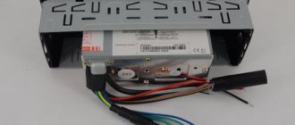
In order to reduce its dimensions, modern welding machines use a circuit consisting of the following units:
- Input rectifier.
- An inverter is an electronic device with fast-switching transistors controlled by a microcircuit.
- Transformer.
- Output rectifier.
The inverter is the arc power source.
The inverter converts direct current into alternating current with a frequency of up to 80 kHz. This allows not only to reduce the size of the transformer, but also to increase the efficiency of the device.
The source parameters are selected taking into account the method of performing the work. For example, during manual welding, the arc length fluctuates, so you need a device with a steeply falling current-voltage characteristic. Thanks to it, the discharge does not go out when stretched, and when it is shortened, the current does not become too large.
When welding with a consumable electrode, drops of metal flow from it onto the workpiece. At such moments, a short circuit current occurs that exceeds the arc current by 20% -50%. It burns out the formed metal bridge, and the plasma discharge is formed again. These fluctuations occur in short moments of time, so the source must quickly respond to them, stabilizing the potential difference.
Recommended reading: Choosing polarity when welding
What and how power is determined
Plasma is a conductor with electric current flowing through it. This means that the question of how the power of a welding arc is determined is given the same answer as for any resistor: voltage and amperage. The rate of heat release is equal to the product of these quantities.
The power varies with the current strength, which depends on the length of the arc.
Increasing the potential difference allows you to increase power only within small limits. In addition, the possibility of such adjustment is limited by the size of the electrode.
More often, the power is varied by the current strength, which, in turn, depends on the length of the arc. At the same time, the heating temperature of the metal changes, and with it the speed of work.
Extinguishing methods
It should be noted that arc extinction occurs for various reasons. For example, as a result of cooling of the column, a voltage drop, or when the air between the electrodes is displaced by external vapors that prevent ionization.
In order to prevent the formation of arcs on high-voltage power line wires, they are spaced over a long distance, which eliminates the possibility of breakdown. If a breakdown between the wires does occur, the long barrel will quickly cool and extinguishment will occur.
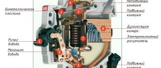
To cool the barrel, it is sometimes divided into several components. This principle is often used in the designs of air circuit breakers designed for voltages up to 1 kV.
Some circuit breaker models contain multiple arc chutes to promote rapid cooling.
Rapid ionization can be achieved by evaporating certain materials surrounding the space of the moving knives. High-pressure evaporation blows away the plasma of the barrel, resulting in extinguishing.
There are other methods: placing contacts in oil, auto-blowing, using electromagnetic damping, etc.
Useful Application
Oddly enough, physicists found application for this electrical phenomenon even at the stage of development of the science of electricity. An example of this is the Yablochkov light bulb . It consisted of two carbon electrodes, between which an electric arc was ignited.
This lamp had two drawbacks. The electrodes quickly wore out (burned out), and the light spectrum shifted to the ultraviolet zone, which negatively affected vision. For these reasons, arc lamps did not find widespread use and were quickly replaced by incandescent lamps, which exist to this day.
The exception is arc-discharge lamps, as well as high-power spotlights used primarily for military purposes. The arc discharge has been widely used in practice since the invention of the welding machine. Arc welding is used for welding metals. (see Fig. 5)
Rice. 5. Arc welding
Using plasma conductivity, including special welding electrodes in the welding circuit, a high temperature is achieved in a concentrated spot. By adjusting the welding current, the welder has the opportunity to adjust the machine to the desired temperature of the arc discharge. To protect the barrel from heat loss, the metal electrodes are coated with a special mixture that ensures combustion stability.
An electric arc is used in blast furnaces for melting metals. Arc melting is convenient in that you can regulate its temperature by changing the current parameters.
Along with useful applications, in electrical engineering we often have to deal with arc discharges. An uncontrolled arc discharge can cause significant damage on power lines, industrial and domestic networks.
Rice. 6. Arc discharge on power lines
Nature and structure
In a short time, the metal can be heated to its melting temperature using a powerful welding arc. Its properties are characterized by current density and current-voltage indicators. From the point of view of electrical engineering, an arc column is an ionized gas conductor between the cathode and anode with high resistance and the ability to glow. A detailed examination of the structure of the welding arc will help to understand the essence of temperature effects. The average length of the electric arc is 5 mm, it is divided into main zones:
- anodic, it is no more than 10 microns;
- cathode, it is 10 times smaller than the anode;
- pillar - a visible luminous strip.
The temperature of the welding arc is determined by the flow of free electrons. They are formed at the cathode spot. It heats up to 38% of the plasma temperature. In an arc column, electrons move towards the anode and positive particles move towards the cathode. The column has no charge of its own; it remains neutral. Inside, the particles are heated to 10,000°C, while the metal is heated on average to 2350°C, the standard temperature of the melt bath is 1700°C.
The place where electrons enter and are neutralized is called the anode spot. Its temperature is 4–6% higher than that of the cathode.
The voltage in the anode and cathode zones is significantly reduced, and no glow occurs. Only plasma that emits ultraviolet, infrared and light waves is visible. They are harmful to the organs of vision and skin. Therefore, welders use personal protective equipment.
Welding arc structure