Transformer design
If you look at the transformer from the outside, it is an W-shaped device consisting of a metal core, a cardboard or plastic frame and a copper wire winding. There are two windings.
The core is several steel plates that are treated with a special varnish and connected to each other. The varnish is applied specifically to prevent tension from passing between the plates. In this way they fight the so-called eddy currents (Foucault currents). The thing is that Foucault currents will simply heat the core itself. And these are losses.
The composition of the core plates is also associated with losses. Transformer iron (as core steel is most often called by experts), if you look at it in cross-section, consists of large crystals, which, in turn, are isolated from each other by an oxide film.
Determination of the cross-section and diameter of the winding wire
Preliminary values of the cross-sections of the winding wires are determined by the formulas:
The final values of cross-sections and diameters of wires are selected according to the closest GOST data from Appendix I:
The transformer winding should be made with a rectangular wire, or with a round wire, the winding should be wound in two or three parallel wires.
The most widely used wires for low-power transformers are PEL, PET and PEV-2 wires with diameters up to 1-2 mm and PBD grades with diameters over 1-2 mm.
The listed wire brands are deciphered as follows:
PEL - enameled, paint-resistant wire; PET - enameled, varnish-resistant wire with increased heat resistance; PEV-2 - wire insulated with high-strength enamel in two layers; PBD is a wire insulated with two layers of cotton yarn winding.
Selecting core window sizes and laying windings on transformer rods
and increases steel consumption and the weight of the transformer. A reduced window height increases the heating of the windings and increases the copper consumption on them.
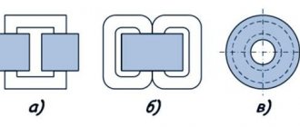
As experience shows, the most advantageous shape of the transformer core window is obtained when the ratio of the window height H to its width b is within the range of 2.5-3 (Fig. 1, 2 and 3).
If, when calculating the transformer core, the standard shape of U-shaped or W-shaped plates from Appendix II is adopted, then the dimensions R and 6 are taken from the same appendix.
When arranging the windings on the transformer core rods, you need to keep the following in mind: the smaller the diameter of the winding wire, the higher its cost. Therefore, to reduce the overall cost of the transformer, it is advisable to place the winding with a thinner wire first on the rod.
To clarify the width of the core window b, it is necessary to calculate the radial thickness of the transformer windings.
Number of turns of the primary winding in one layer:
— taken from position 5;
rounds to the nearest larger integer.
Primary winding thickness:
- taken from position 5. Number of turns of the secondary winding in one layer:
Number of layers of the secondary winding of a single-phase single-coil or three-phase transformer (Fig. 10, b and c):
also rounds to the nearest higher integer.
In a single-phase double-jaw transformer
(Fig. 10, a). Secondary winding thickness:
taken from position 5.
Width of the core window of a single-phase transformer with one round coil (Fig. 10.6):
- gap from the rod to the coil (Fig. 10.6);
- the thickness of the insulation between the coil and the rod, usually made of electrical cardboard;
- the thickness of the insulation between the windings, usually made in low-power transformers from electron rton and varnished cloth with a thickness of 0.10-1.0 mm;
— thickness of the corresponding windings, mm.
The window width of a single-phase transformer with two round coils, as well as a three-phase transformer with similar coils (Fig. 10, a):
The window width of a single-phase transformer is one! rectangular coil (Fig. 10, c):
—( thickness increase factor
coils due to the loose fit of the layers, as a result of which the coil takes on an oval appearance.
Window width of a single-phase transformer with two rectangular coils, as well as a three-phase transformer with similar coils:
Source: www.tehnoinfa.ru
Purpose and functionality
So, what functions does a transformer perform?
- This is a reduction in voltage to the required parameters.
- With its help, the galvanic isolation of the network is reduced.
As for the second function, it is necessary to give explanations. Both windings (primary and secondary) of the current transformer are not directly connected to each other. This means that the resistance of the device, in fact, should be infinite. True, this is an ideal option. The connection of the windings occurs through the magnetic field created by the primary winding. This is such a complex functionality.
Alternative method for dimensions
The approximate parameters of the transformer, based on the available core, can be determined in another way, and then conclusions can be drawn about the possibility of further use.
Knowing the cross-sectional area of the magnetic circuit in square centimeters, you can estimate the maximum power that this converter is capable of providing:
It should be borne in mind that this power is dimensional, and the real one will have a smaller value:
Usually, provided that the calculated power matches the required one, the primary winding connected to the 220 V network can be left untouched, recalculating only the parameters at the outputs.
Calculation
There are several types of calculations used by professionals. For beginners, they are all quite complex, so we recommend the so-called simplified version. It is based on four formulas.
The transformer allows you to reduce the voltage to the required parameters.
Formula of the law of transformation
So, the transformation law is determined by the following formula:
U1/U2=n1/n2, where:
- U1 – voltage on the primary winding,
- U2 – on the secondary,
- n1 – number of turns on the primary winding,
- n2 – on the secondary.
Table of volts per turn
In order not to constantly carry out calculations, you can use the table, which shows the average data of the windings depending on the power:
| Power, P | Section in cm2, S | Number of vit. /B, W | Power, P | Section in cm2, S | Number of vit. /B, W |
| 1 | 1.4 | 32 | 50 | 9.0 | 5.0 |
| 2 | 2.1 | 21 | 60 | 9.8 | 4.6 |
| 5 | 3.6 | 13 | 70 | 10.3 | 4.3 |
| 10 | 4.6 | 9.8 | 80 | 11.0 | 4.1 |
| 15 | 5.5 | 8.4 | 90 | 11.7 | 3.9 |
| 20 | 6.2 | 7.3 | 100 | 12.3 | 3.7 |
| 25 | 6.6 | 6.7 | 120 | 13.4 | 3.4 |
| 30 | 7.3 | 6.2 | 150 | 15.0 | 3.0 |
| 40 | 8.3 | 5.4 | 200 | 17.3 | 2.6 |
Possible schematic solutions
There are two connection diagrams for the secondary winding of transformers, and indeed all electronics:
- A star that is used to increase the power of the network.
- A triangle that maintains constant voltage in the network.
Regardless of the chosen scheme, the most difficult is the manufacture and connection of small transformers. This includes atx, which is so popular in search engine queries. This is a model that is installed in computer system units, and it is extremely difficult to make it yourself.
Difficulties in the manufacture of small transformers include the complexity of the winding and insulation, the correct connection of the secondary winding, regardless of the chosen circuit, as well as the difficulty of finding a core. In short, it is easier and cheaper to buy such a transformer. But how to choose the right model is a completely different story.
Selecting a magnetic core
The minimum cross-section of the core in cm2 is determined from the overall power. The overall power of a transformer is the total total power of all secondary windings, taking into account efficiency.
Calculation of a resistor for an LED
So, the power of the transformer can be determined, this is the total total power of all secondary windings:
By multiplying the resulting value by the efficiency, we complete the calculation of the overall power.
The area of the core rod is determined after the overall power of the transformer has been calculated from the following expression:
S=√P.
Knowing the cross-sectional area of the central core of the magnetic core, you can select the desired one from ready-made options.
Important! The core on which the windings will be located should, if possible, have a cross-section as close to square as possible. The cross-sectional area should be equal to or slightly larger than the calculated value.
The quality of work and manufacturability of the assembly also depends on the shape of the magnetic core. The best quality is achieved by designs made on a ring magnetic core (toroidal). They are distinguished by maximum efficiency for a given power, lowest no-load current and minimum weight. The main difficulty lies in making the windings, which at home have to be wound exclusively by hand using a shuttle.
The easiest way to make transformers is on split tape magnetic cores of the ShL (W-shaped) or PL (U-shaped) type. As an example, we can cite a powerful transformer for the power supply of an old color TV.
TV transformer ULPTsTI
Old-time or modern cheap transformers are made using separate W- or U-shaped plates. The manufacturability of their windings is the same as that of split tape windings, but the difficulty lies in assembling the magnetic core. Such devices will almost always have an increased no-load current, especially if the iron used is of poor quality.
Recommendations for assembly and winding
When assembling a transformer with your own hands, the core plates are assembled “over the roof”. The magnetic core is tightened with a clip or hairpin nuts. In order not to damage the insulation, the studs are covered with a dielectric. You need to tighten the hardware with force: if it is not enough, a hum will occur during operation of the device.
The conductors are wound onto the coil tightly and evenly, each subsequent row is insulated from the previous one with thin paper or Mylar film. The last row is wrapped with keeper tape or varnished cloth. If a tap is made during the winding process, the wire breaks, and a tap is soldered in place of the break. This place is carefully isolated. The ends of the windings are secured with threads that tie the wires to the surface of the core.
There is a trick: after the primary winding, you should not wind the entire secondary winding at once. Having wound 10-20 turns, you need to measure the voltage at its ends.
Based on the obtained value, you can imagine how many turns will be required to obtain the required amplitude of the output voltage, thereby controlling the resulting calculation when assembling the transformer.
Sources
- https://regionvtormet.ru/instrumenty/raschet-moshhnosti-transformatora-na-sterzhnevom-magnitoprovode-vruchnuyu-i-pri-pomoshhi-onlajn-kalkulyatora.html
- https://met-lit.ru/instrument/raschet-transformatora-po-secheniyu-serdechnika-kalkulyator.html
- https://master-pmg.ru/oborudovanie/raschet-transformatora-onlajn.html
- https://instanko.ru/elektrichestvo/raschet-transformatora-onlajn-kalkulyator.html
- https://www.kupi-elektriku.ru/izmereniya-i-raschyot/raschet-transformatora-svoimi-rukami-onlayn-kal-kulyatory-osobennosti-avtotransformatorov-i-torov/
- https://energo-novgorod.ru/calcs/calc-trans/
- https://ElectrikBlog.ru/raschet-transformatora-onlajn-kalkulyator/
- https://vdn-plus.ru/kak-rasschitat-transformator-toka-po-serdechniku/
- https://gyrator.ru/transformer-calculation